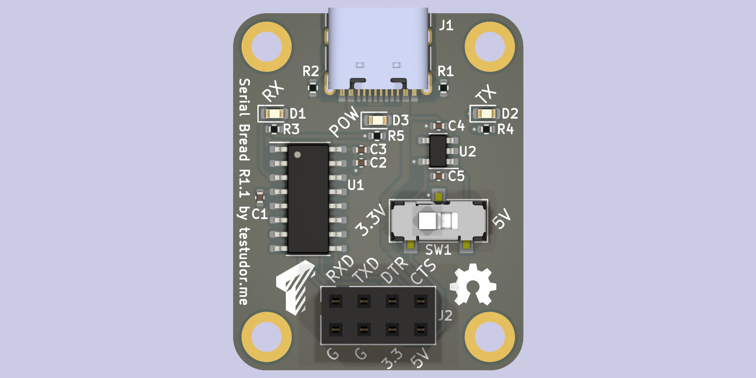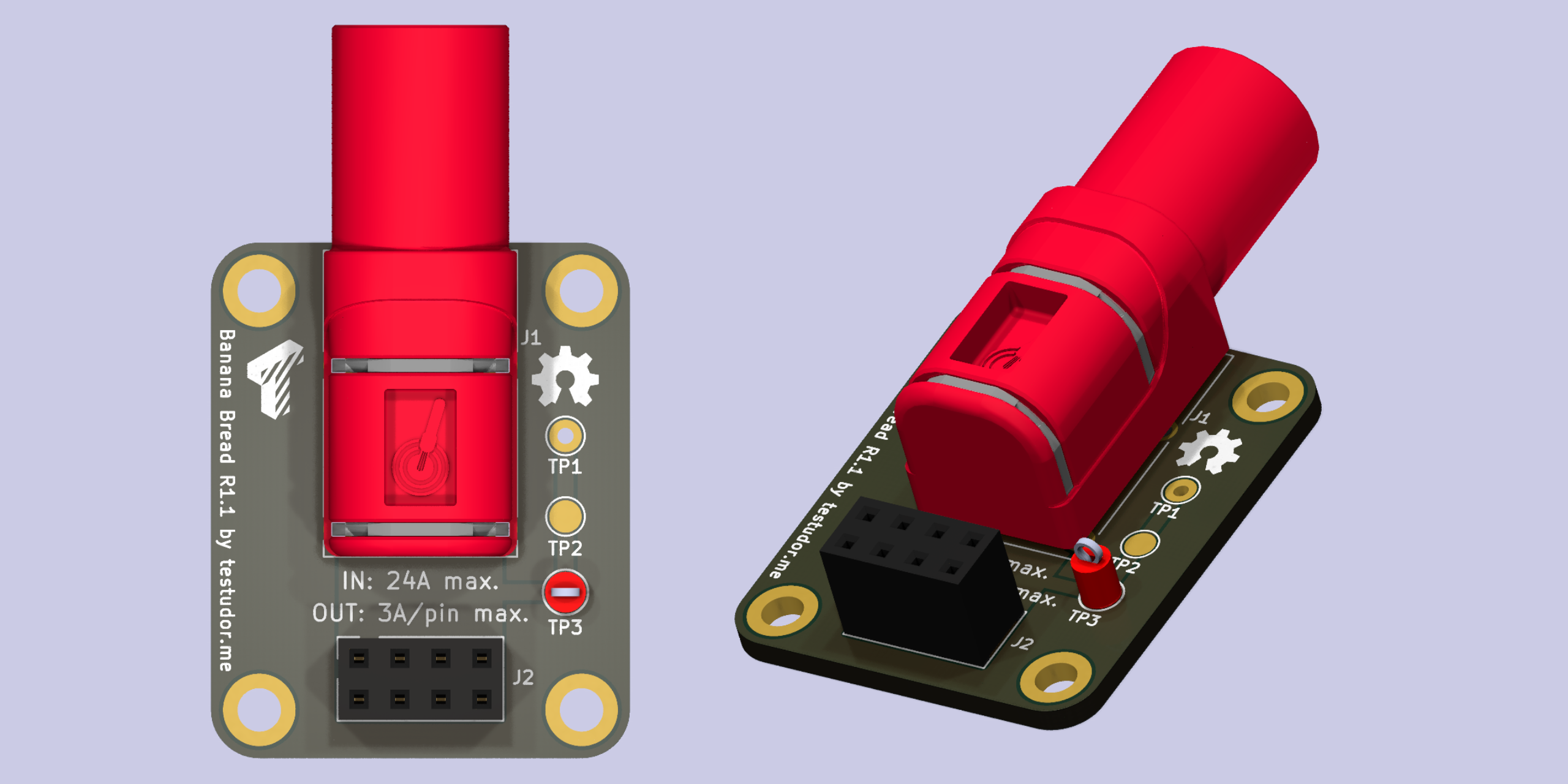
I am currently working on an improved baseplate, which can be either machined from plastic or be 3D printed. Since tapping M2.5 threads in plastic is pretty pointless, I will replace them with either heat-set or press-fit threaded inserts. The PCBs will need to change slightly as well, specifically the keep-out zone on the bottom layer. I took this opportunity to improve a number of things in the existing modules.
Serial Bread

Better LEDs
Before, the RX and TX LEDs were very close together, and it was hard to make out which ones light up unless you looked closely. I moved them to opposing board edges, so they can easily be distinguished, even from a distance.
Additionally, I added a power LED for easier troubleshooting.
Easier logic-level switching
I added a slide switch for changing the logic level, which replaces a fiddly 2mm jumper.
Banana Bread

Continuous 24A, this time for real
I finally got a PSU powerful enough to test the advertised 24A current capability of the old board, and it didn't work out too well. While the board didn't catch fire, it got too hot to touch. I did use a PCB trace width calculator, but it seems I made a mistake.
The new board uses wider traces as well as 2 oz instead of 1 oz copper and should easily handle the 24 amps.
Using the free PCB real estate
Since it makes almost no difference in cost, I added some additional stuff, which could come in handy:
A 2mm test pad
A 1mm via, which prevents standard multimeter probes from slipping
A loop-style through-hole test point
 testudor | Jakob
Discussions
Become a Hackaday.io Member
Create an account to leave a comment. Already have an account? Log In.