M. Bindhammer
-
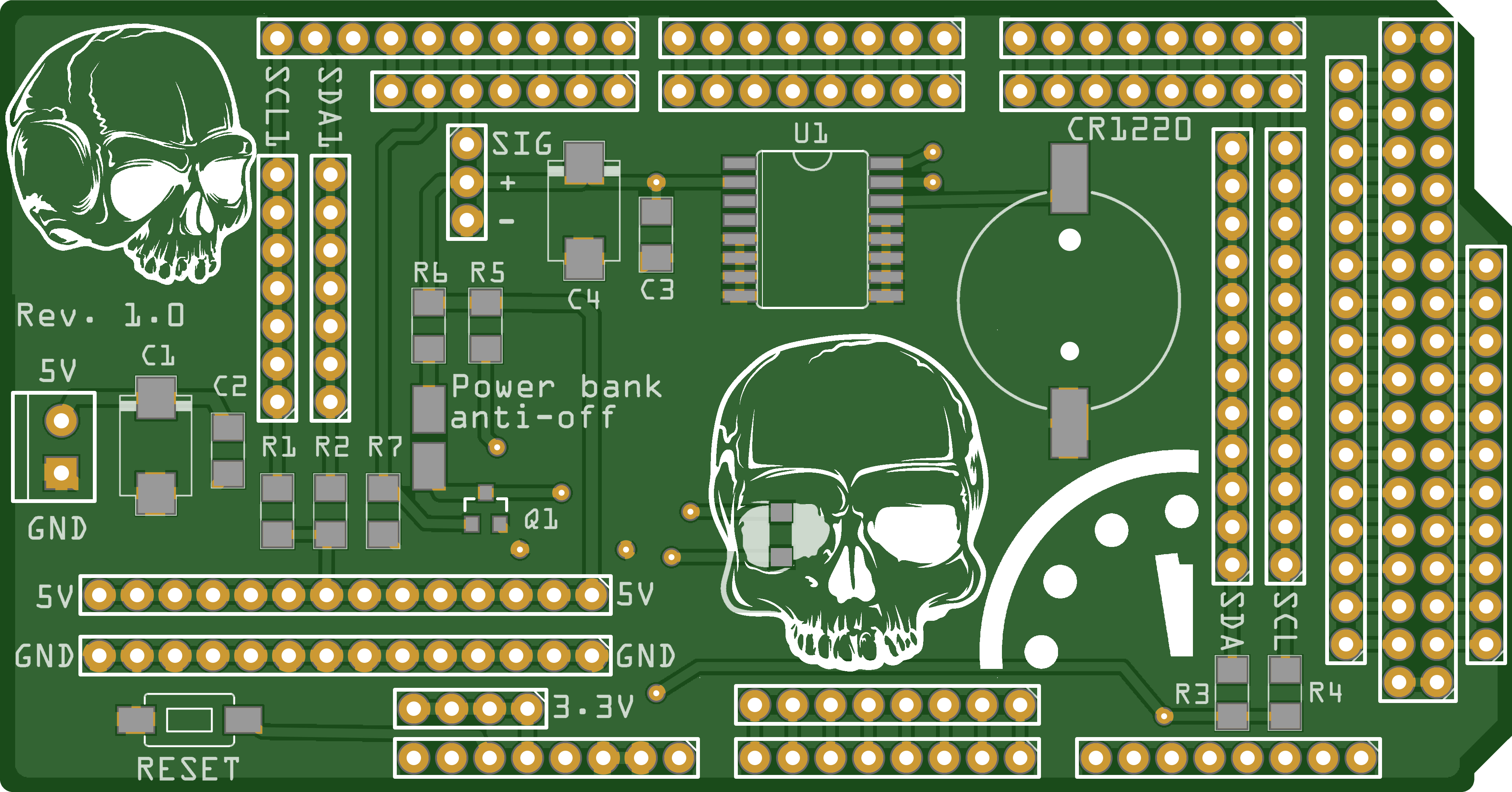
Shield design
03/25/2023 at 13:25 • 0 commentsNothing fancy, mainly power and I2C distribution, a power bank anti-off, and an RTC for the doomsday clock.
![]()
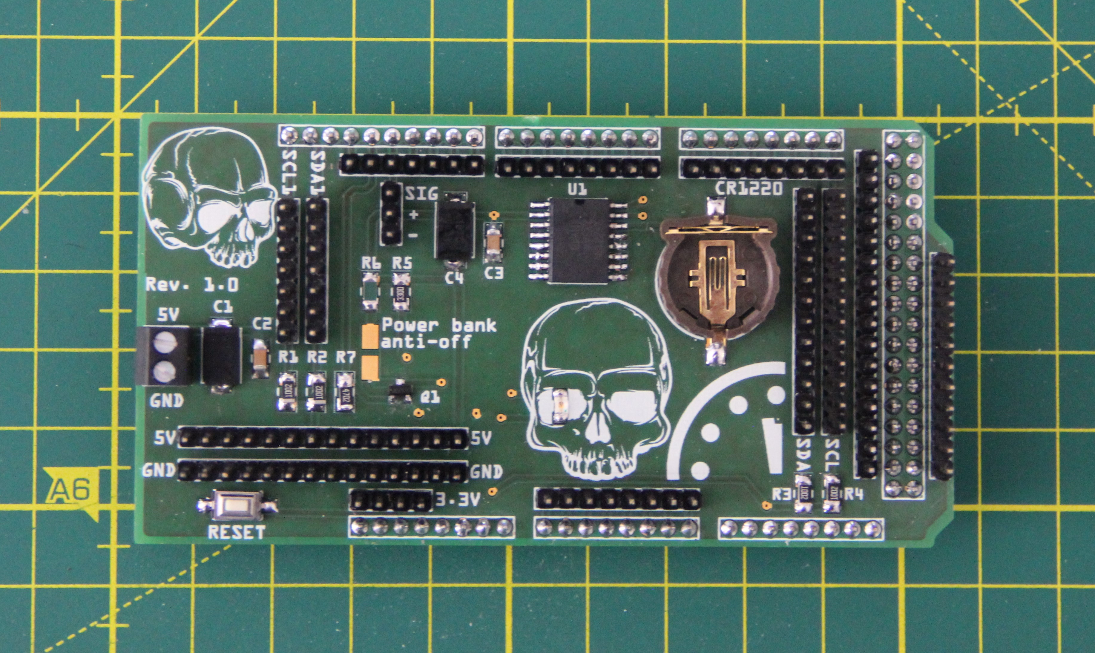
Populated PCB:
![]()
-
Gas sensor
03/18/2023 at 11:01 • 0 commentsI use the MiCS5524 gas sensor, mainly because it is sensitive to carbon monoxide. Carbon monoxide is a highly toxic, colorless, odorless, and tasteless gas. The gas sensor can also detect other gases, but except for hydrogen, our sense of smell can detect and assign them with the exception of methane, propane, and iso-butane, which smell very similar. Here is an excerpt from the data sheet showing the resistance Rs as a function of the concentration of the various gases:
![]()
In the laboratory, a steady stream of carbon monoxide can be produced by dropping formic acid into warm, concentrated sulfuric or phosphoric acid:
That will help us to calibrate the sensor. In fact, we need a second point to calculate the straight-line equation. The sensor must be aged for 24 hours before any characterization or calibration. That is, it must run in clear air for 24 hours.
The two-point form of the linear equation is given by:
y is thereby the analogRead() value and x is the concentration. To calculate the concentration, we need to solve the linear equation for x:
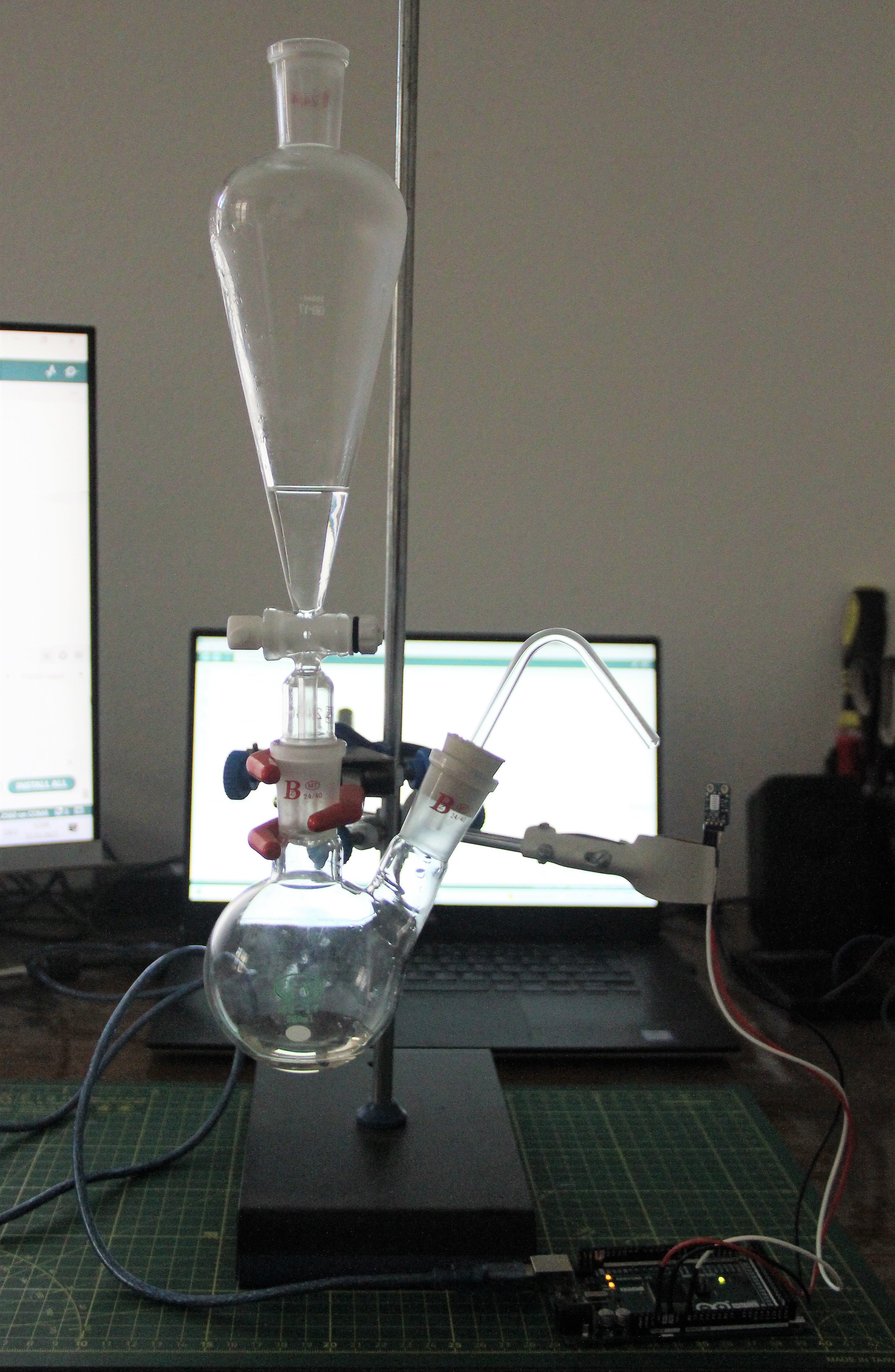
The experimental setup for calibration was as follows. I used 96% sulfuric acid and 70% formic acid. As soon as the formic acid comes into contact with the sulfuric acid, carbon monoxide is produced:
![]()
![]()
The highest analogRead() value I obtained was 1005 in the carbon monoxide stream. In clean air, the analogRead() value is about 25. If we assume that an analogRead() value of 25 corresponds to 1ppm and an analogRead() value of 1005 corresponds to 1000ppm, we can plug the numbers into the straight line equation and get:
Of course, the whole thing is not particularly accurate, but I'll settle for it for now.
-
Biosensor
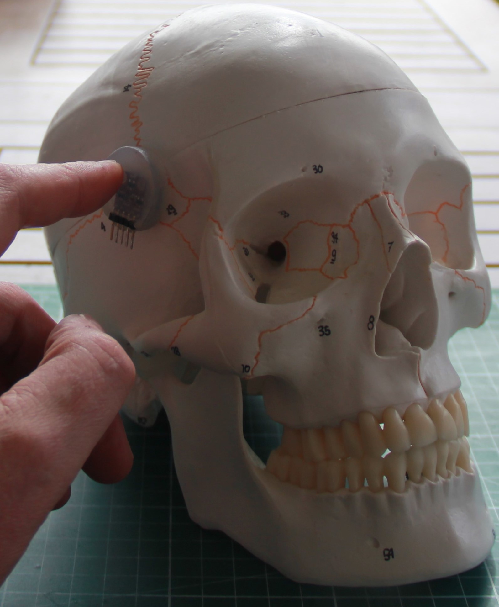
03/14/2023 at 11:27 • 0 commentsI use the MAX30102, an integrated pulse oximeter and heart rate monitor, as the biosensor. It can also be used to measure body temperature. Since the sensor has to lay very well on the skin, I cast it in 2-component silicone. After some experiments, it is possible to perform the measurements on the temple. Since the integrated LEDs can be switched on and off in real-time via the software and you can also change their brightness, machine learning can be applied.
![]()
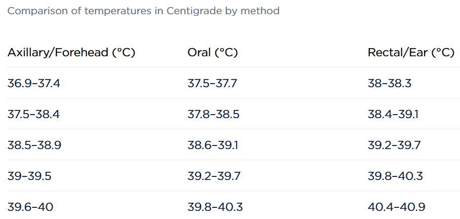
Since we measure temperature at the temple, we need to convert it to body temperature. This chart from here is very useful for that.
![]()
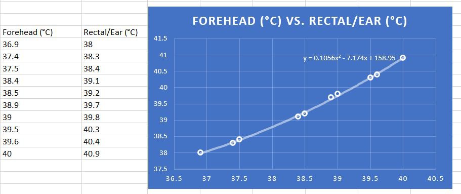
To get a corresponding function, I entered the values in an Excel sheet, created a scatter plot, and chose a second-degree polynomial as a trend line. Excel then outputs the function automatically.
![]()
-
Extended hearing
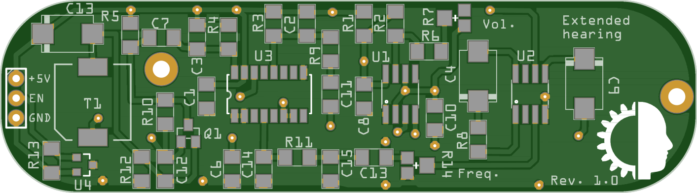
03/12/2023 at 17:59 • 0 commentsThe following circuit is not from me but from Burkhard Kainka. I have redrawn it and modified it a bit. So I use only one voltage and I added a MOSFET switch. It is basically a bat detector, but you can make many other noise sources audible with it. The interesting thing about the circuit is that an AM/FM radio chip (CD2003) is used in the core.
![]()
PCB layout top:
![]()
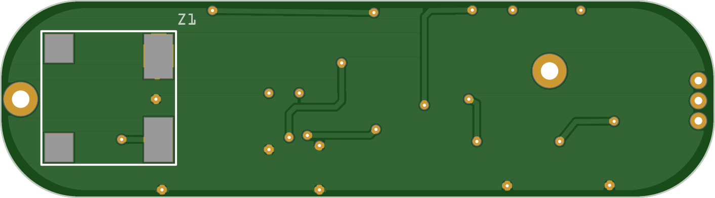
Bottom:
![]()
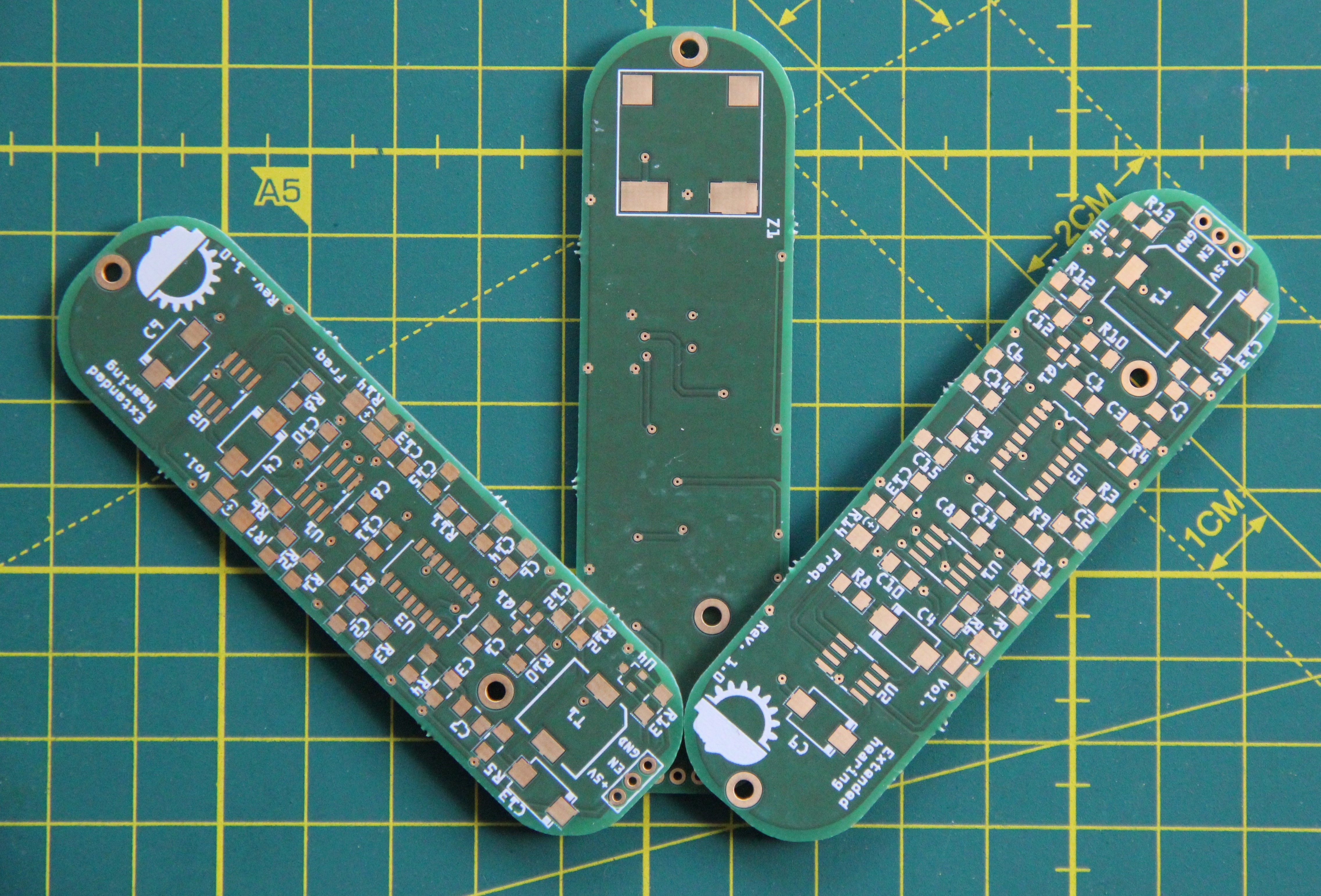
PCBs:
![]()
-
Digital voice changer
03/06/2023 at 12:57 • 0 commentsDuring my research, I came across the MSM6322 speech pitch control chip. It can be controlled very easily via a microcontroller. You can change the voice in real time, which is pretty cool. Since the chip is still available from some sources, I decided to use it. The first draft of the schematic looks like the following:
![]()
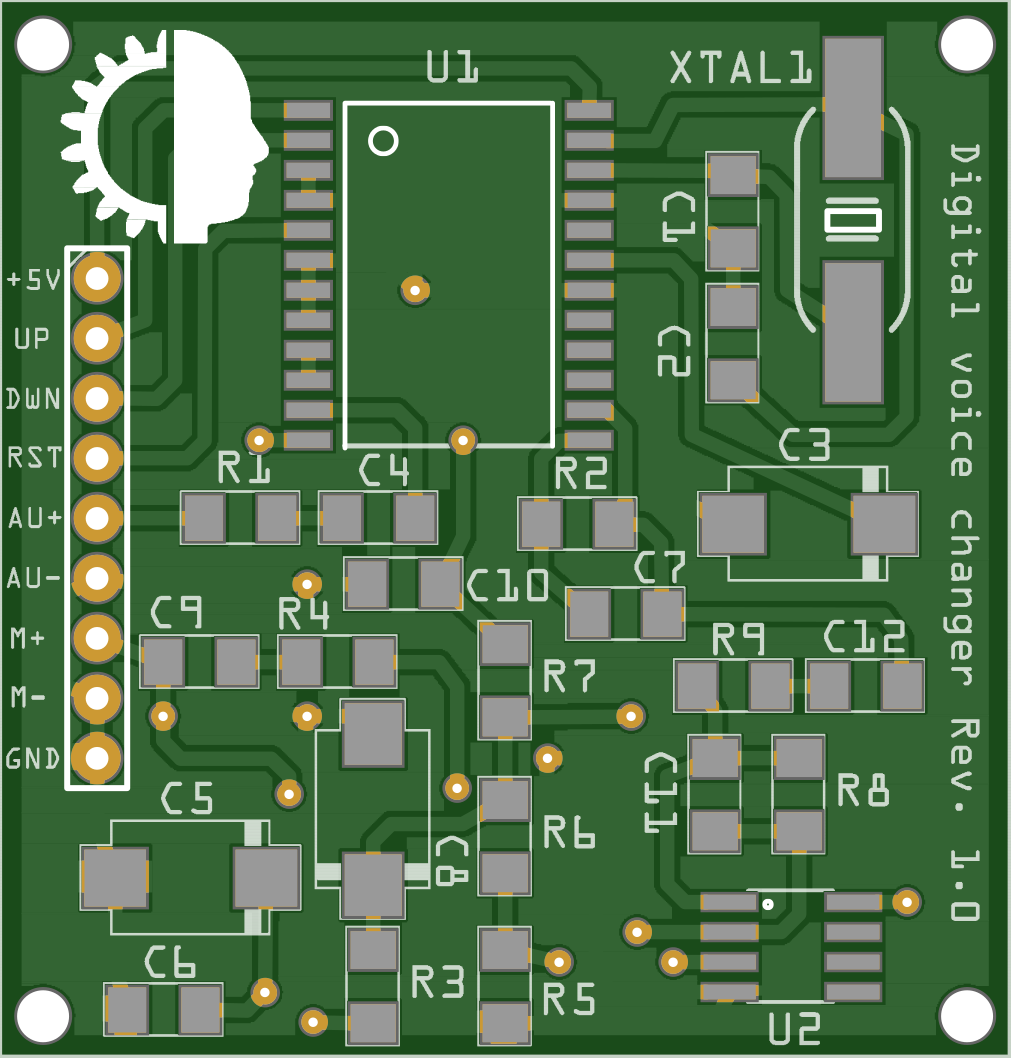
PCB layout:
![]()
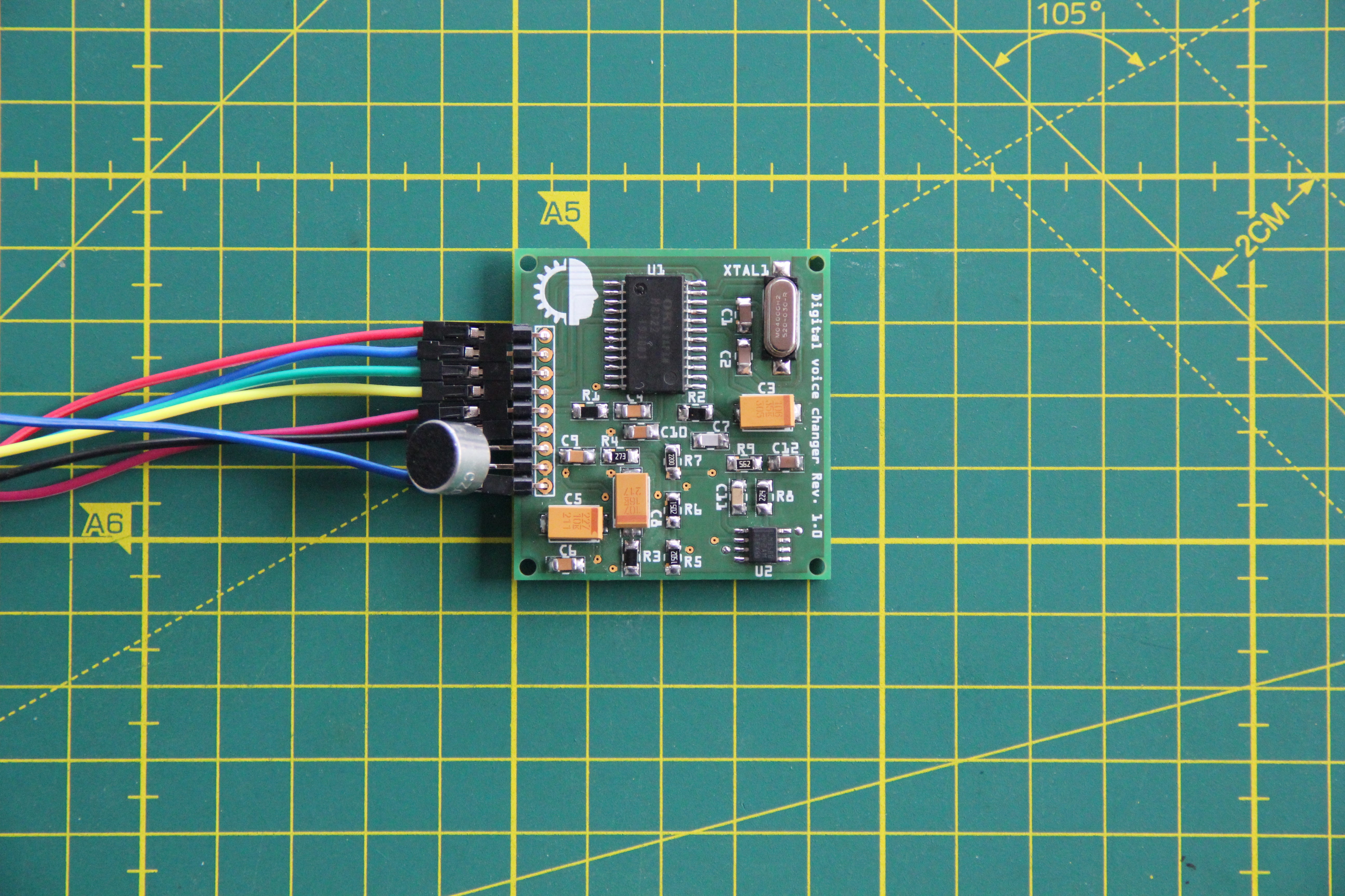
Populated and tested circuit PCB. Works as desired:
![]()
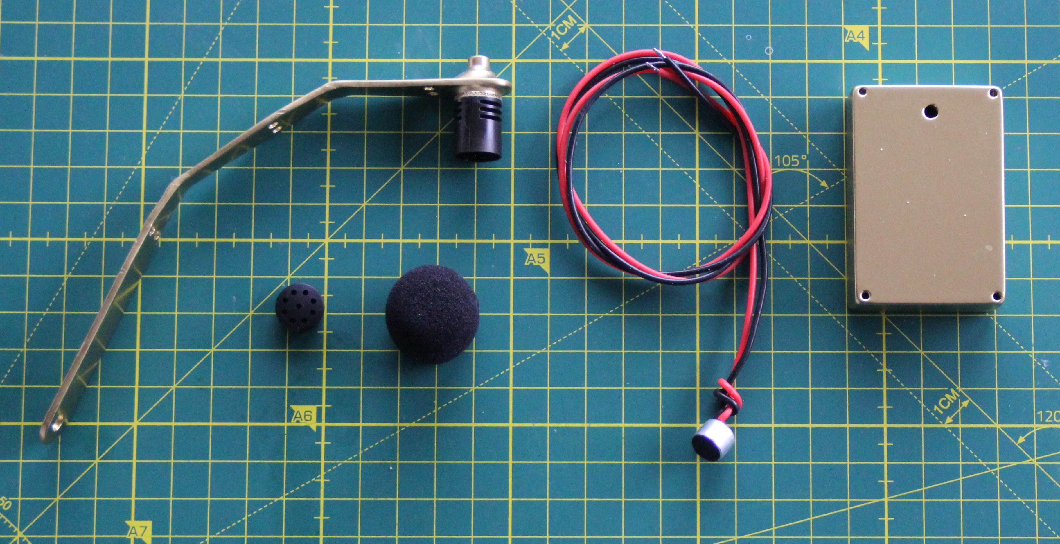
The microphone holder consists of a custom-made part and parts of a cheap clip-on microphone. I soldered new wires to the electret microphone. I also made a sound box for the speaker.
![]()
-
Human-machine interface
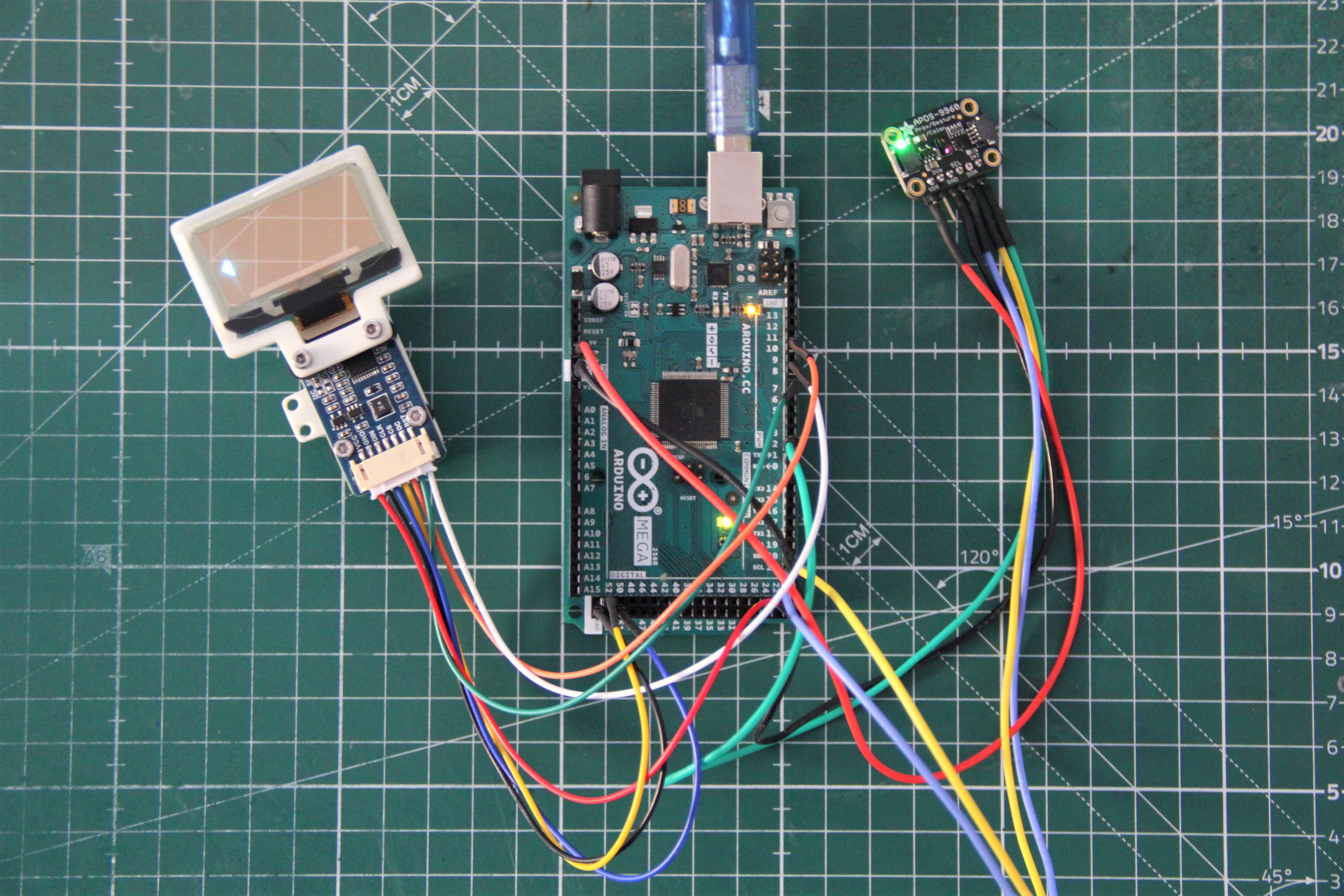
03/04/2023 at 07:47 • 0 commentsAs a human-machine interface, I use the APDS-9960, which can detect hand gestures and measure ambient light and colors. By the way, the sensor is also used in the Samsung Galaxy S5. I use the breakout board from Adafruit because it already has a level shifter integrated.
![]()
-
Substance supply system
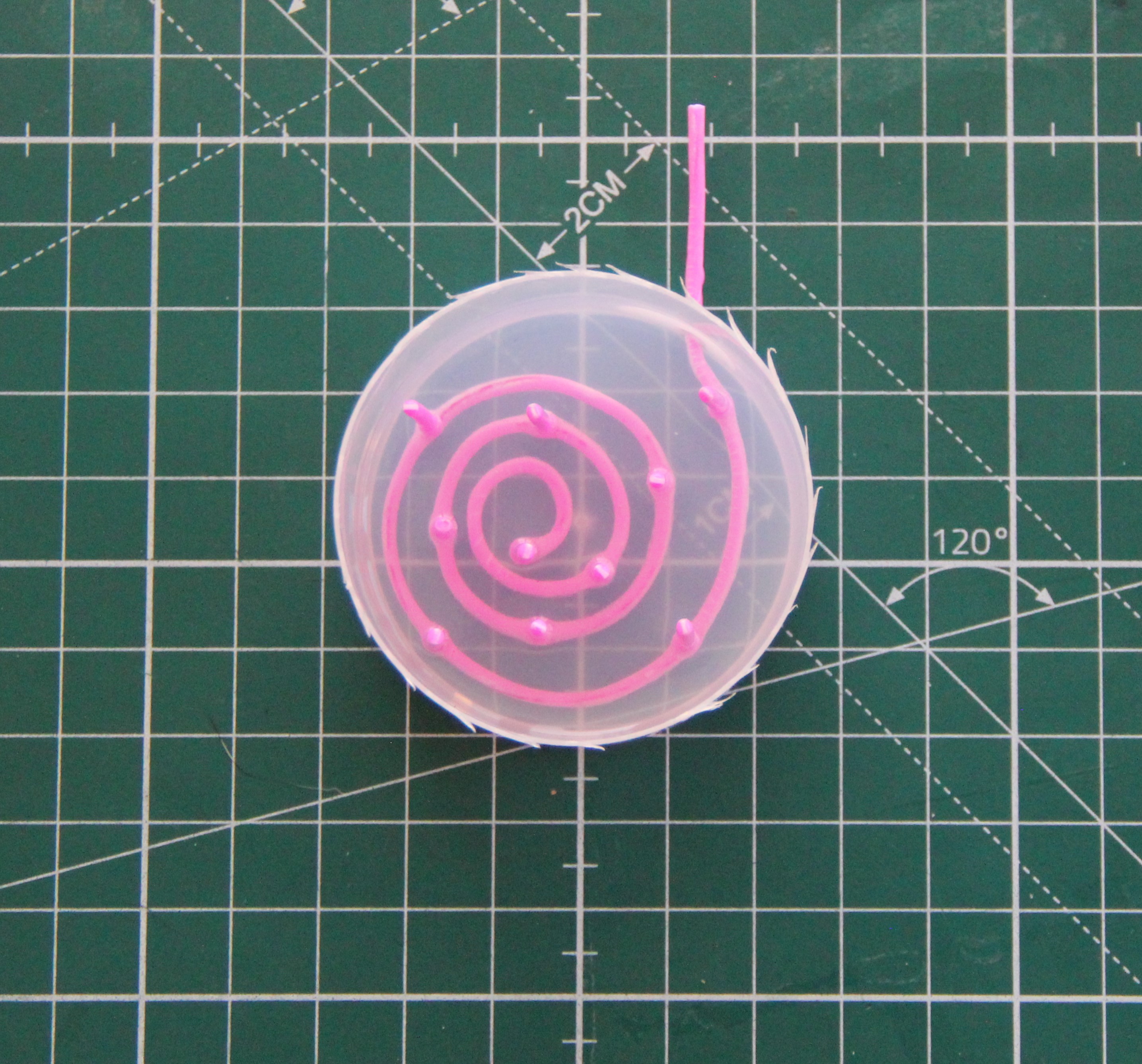
02/26/2023 at 07:55 • 0 commentsSince the substances should be distributed over a large area and evenly on the skin, I designed a microfluid pad. For this purpose, a corresponding structure was built using ABS filament and then cast in 2-component silicone. Next, it was degassed by a vacuum chamber. After curing, the cast was placed in acetone. The acetone dissolves the ABS filament but does not attack the silicone.
![]()
![]()
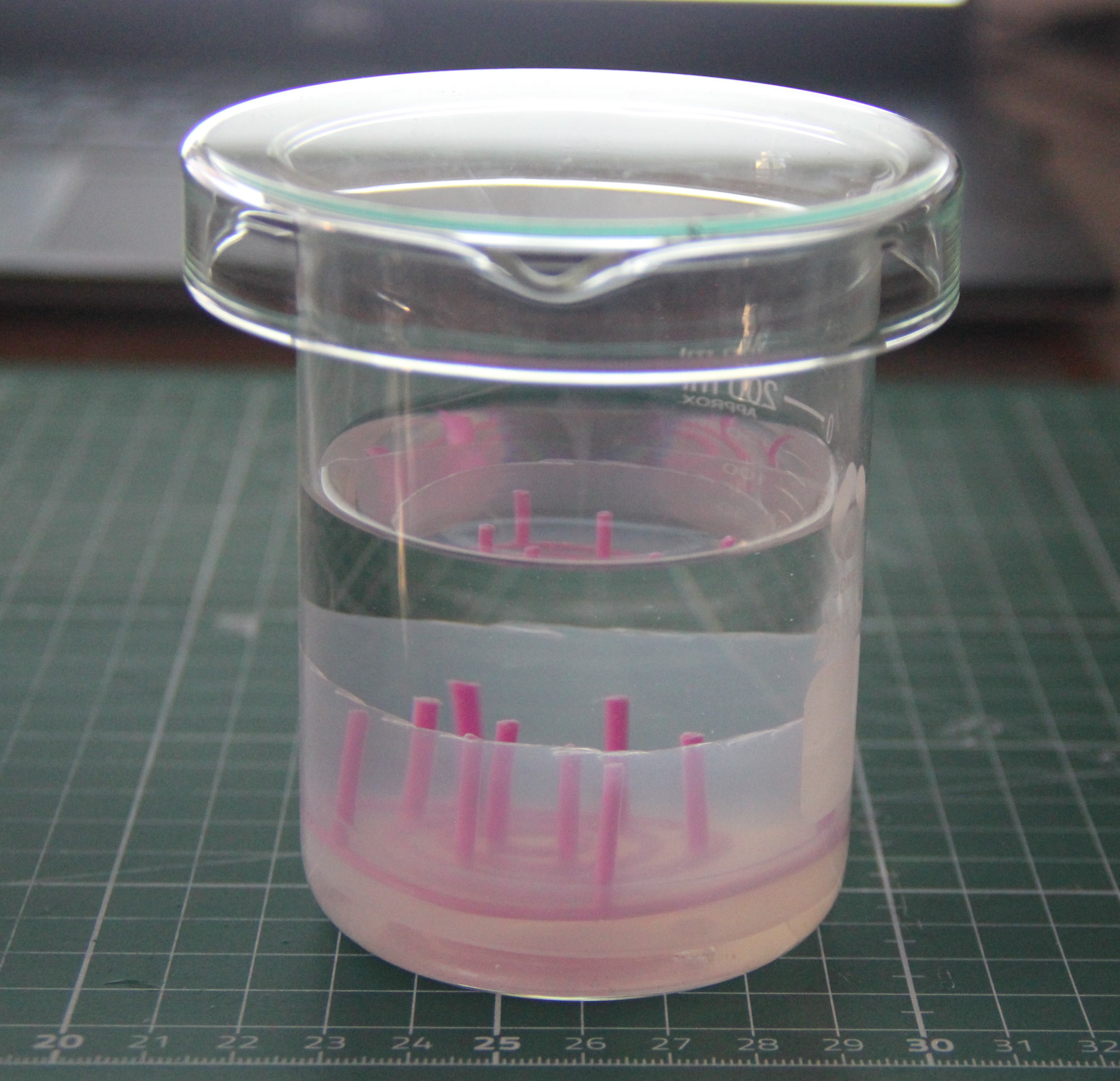
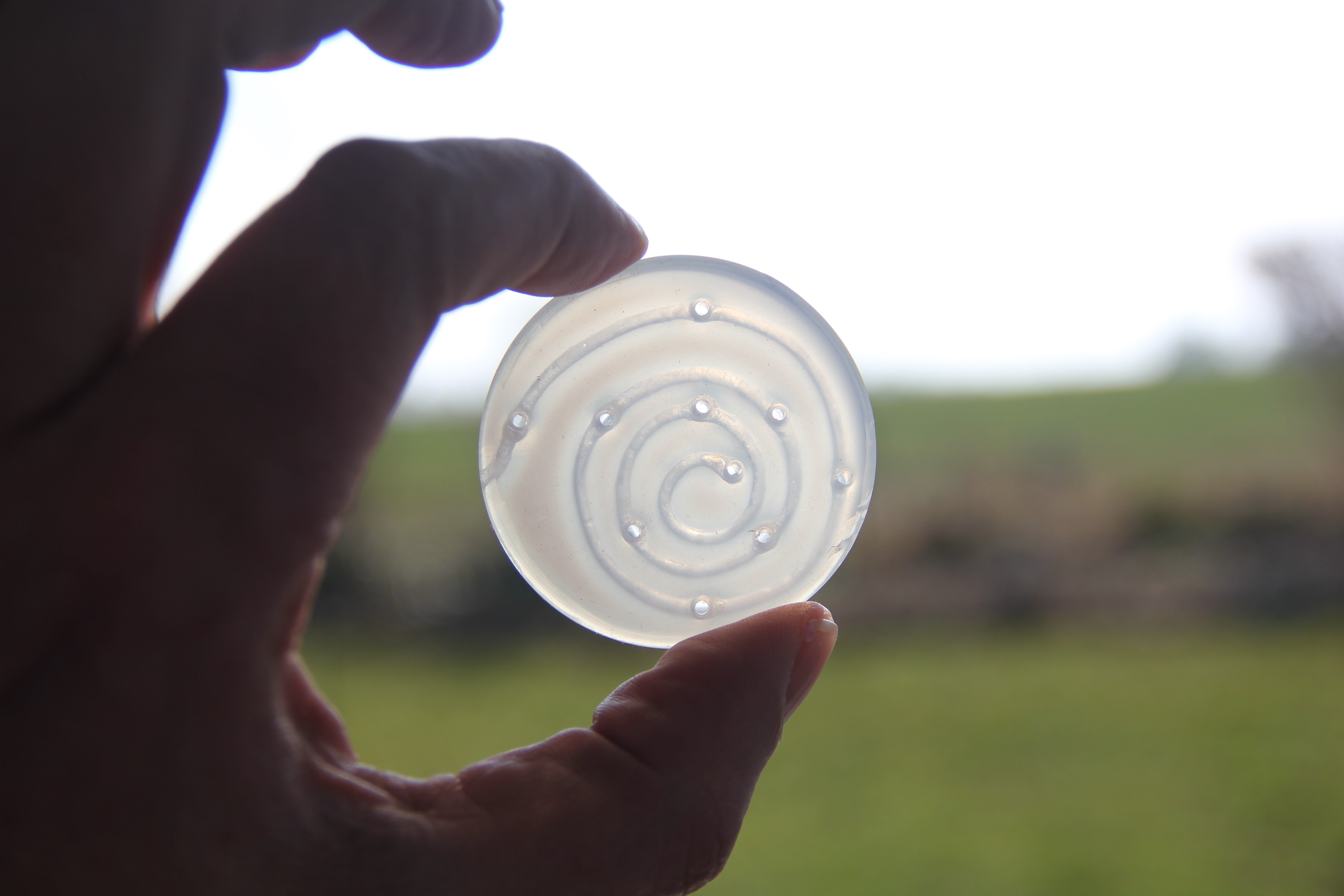
After one day in the acetone solution, the channels were flushed using a small syringe to remove the dissolved acrylonitrile butadiene styrene. Then the silicone mold was placed in fresh acetone solution for another day, followed by a few hours in a 10% hydrogen peroxide solution. Finally, the silicone mold was rinsed several times using hot distilled water.
![]()
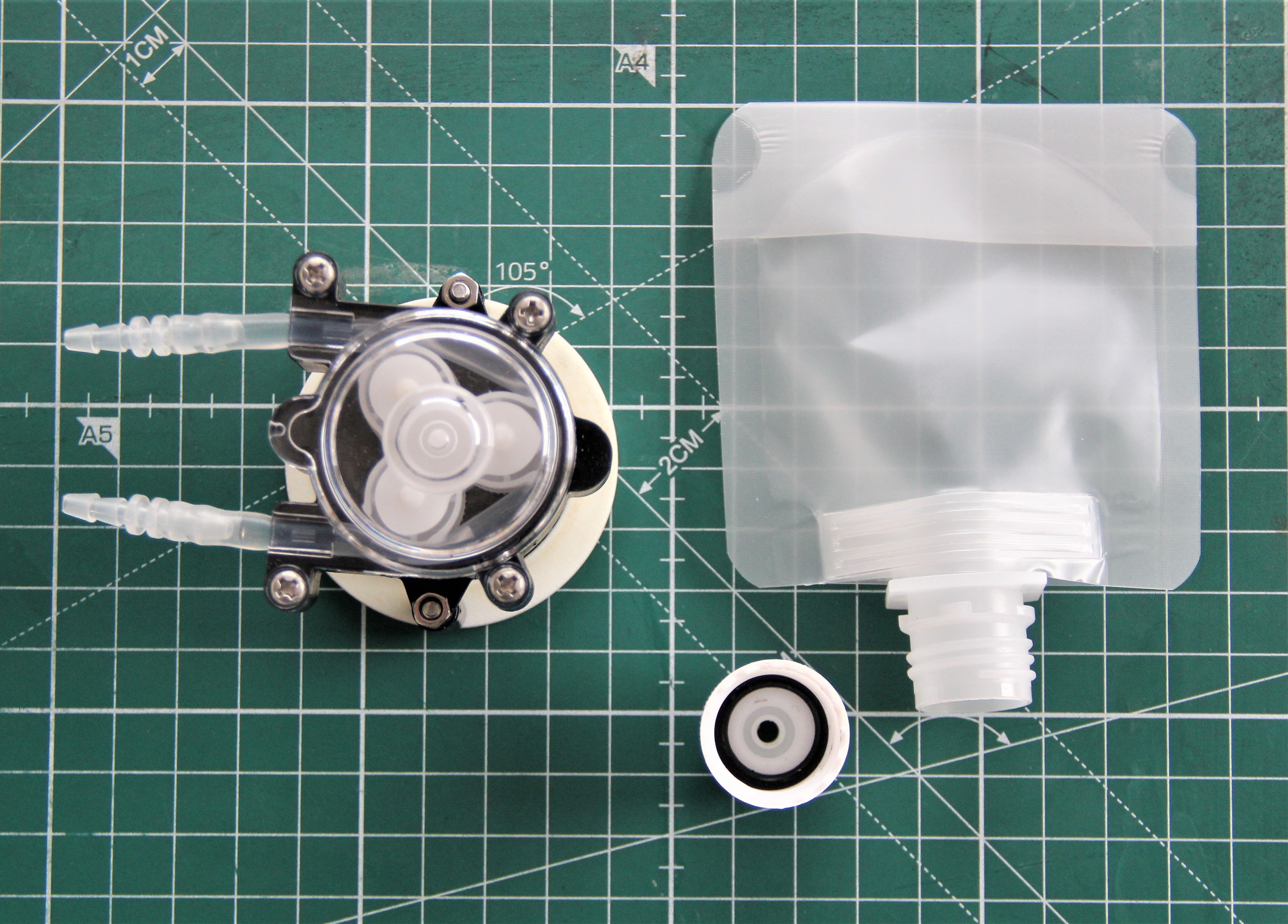
In addition to the microfluid pad, the system consists of a 6V peristaltic pump and a reservoir – a modified liquid bag for airplanes with a capacity of 30ml.
![]()
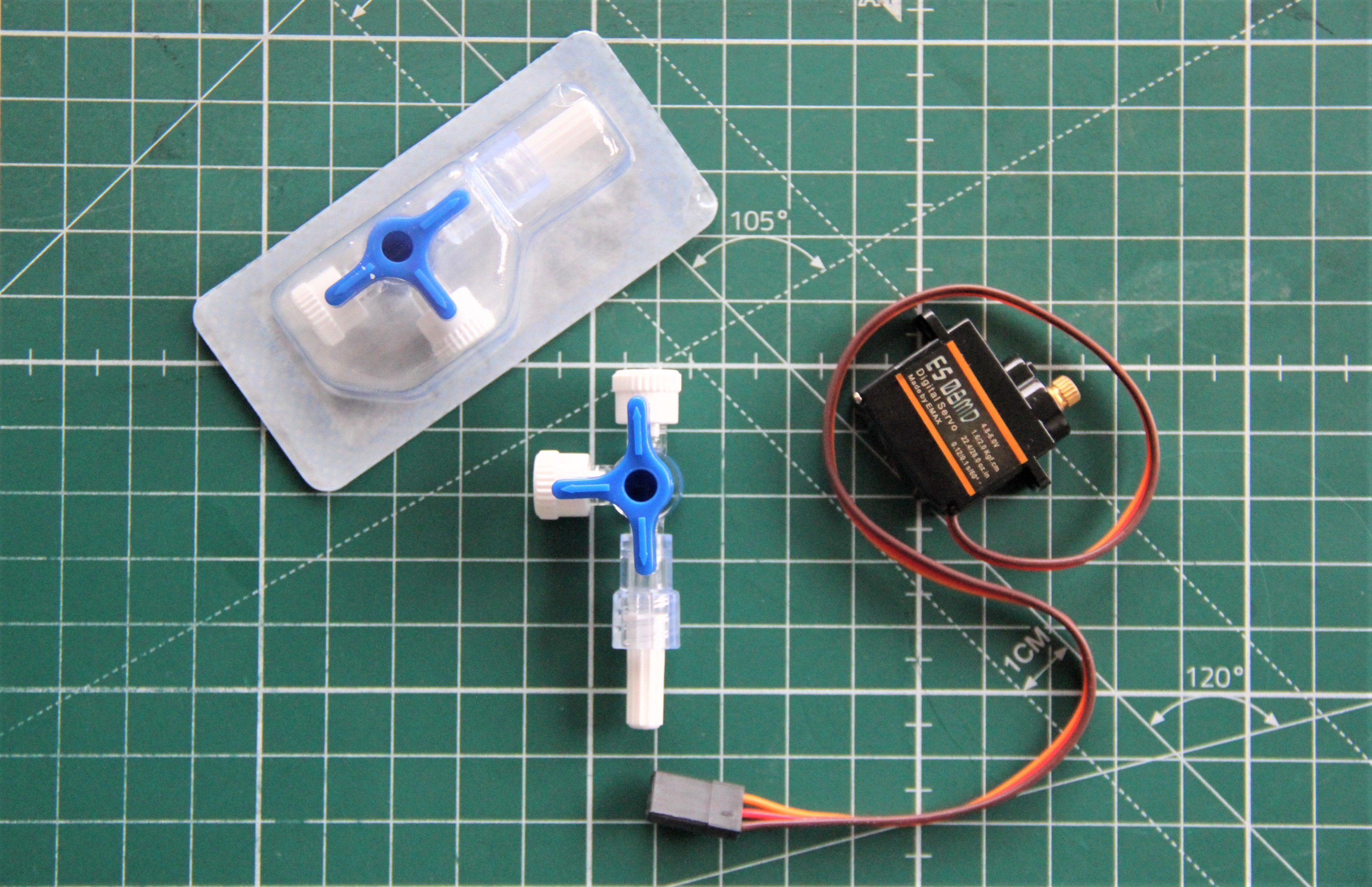
A three-way valve controlled by a servo would also be desirable. Then you could use two reservoirs and even mix substances. There are small and cheap medical three-way valves that are actually intended for infusions. It should not be too difficult to hack one of these.
![]()
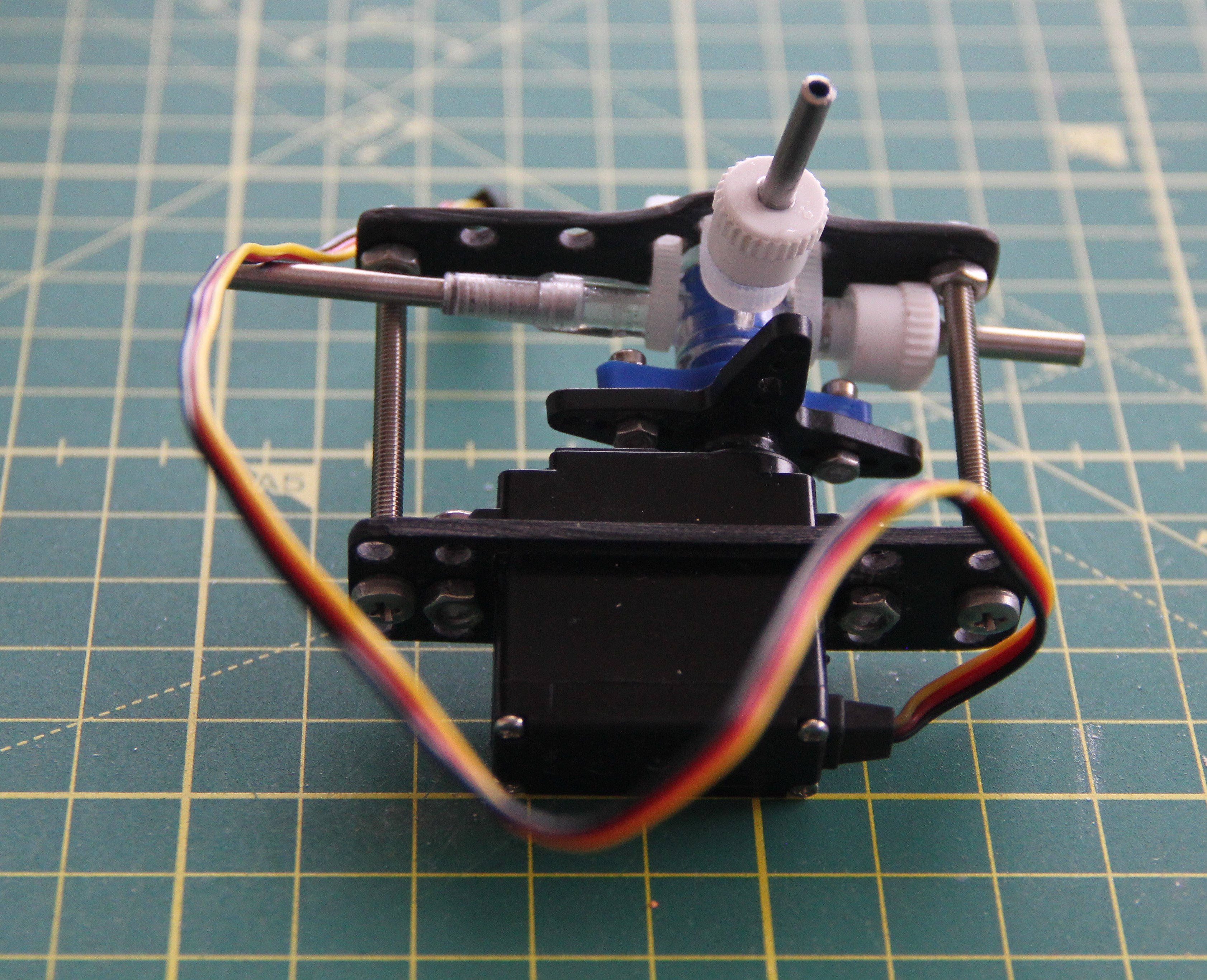
Since the plug of the three-way valve is pressed in, it is somewhat stiff. The ES08 servo has too little torque for this. Therefore I took a Hitec HS-85 MG servo for the prototype. I used 3x2mm stainless steel tubes for the three ports, which were glued with 2-component epoxy glue. The two mounts were cut out of a 2mm GRP plate. These GRP plates are excellent for prototyping, as they are very easy to work with and extremely sturdy.
![]()
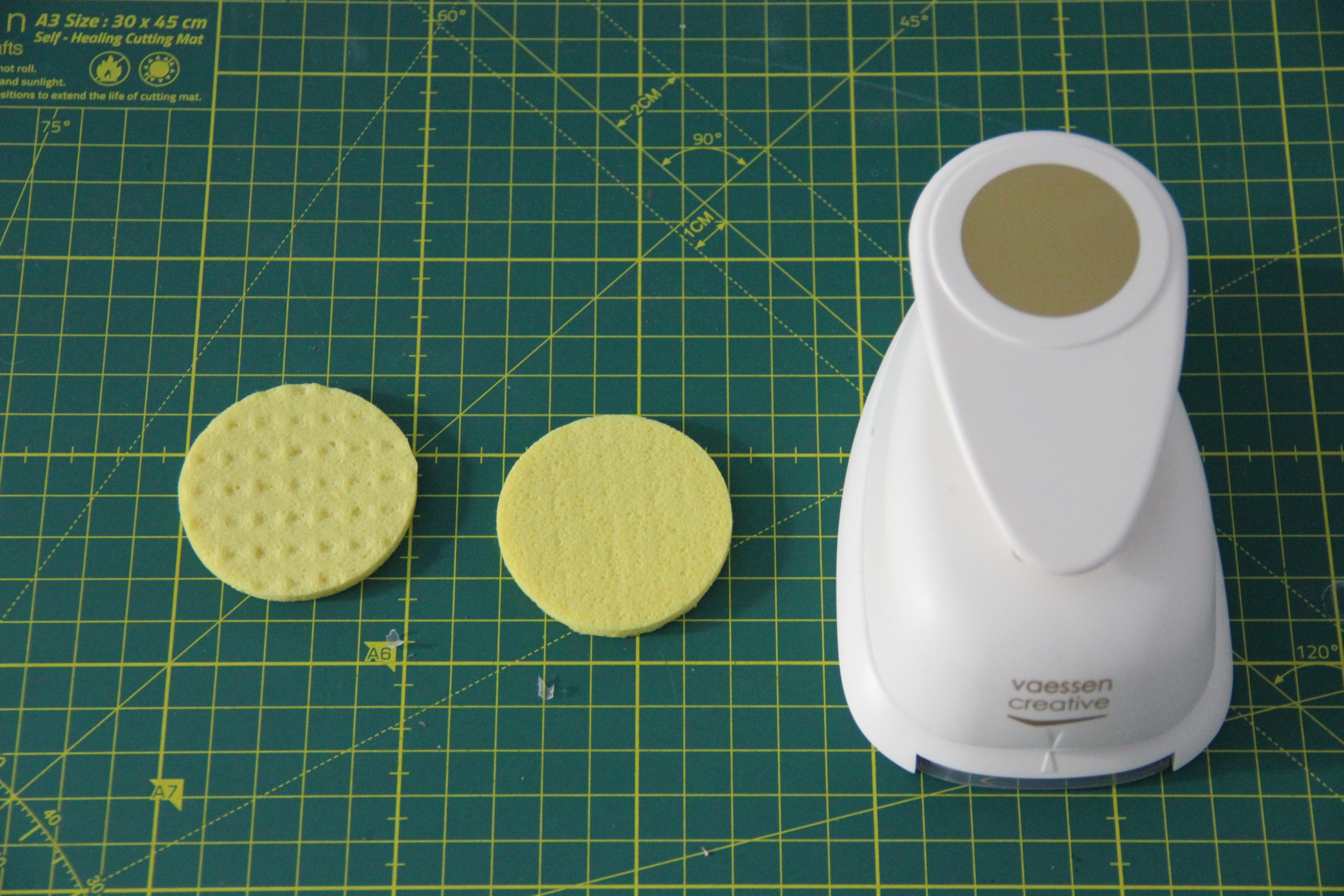
The microfluid pad cannot be placed directly on the skin, as the skin would close the channels. After experimenting with different materials, a cellulose sponge cloth turned out to be the most suitable. Using an appropriate hole punch, I punched out a disc whose diameter corresponds to the microfluid pad. This works best when the sponge cloth is damp.
![]()
-
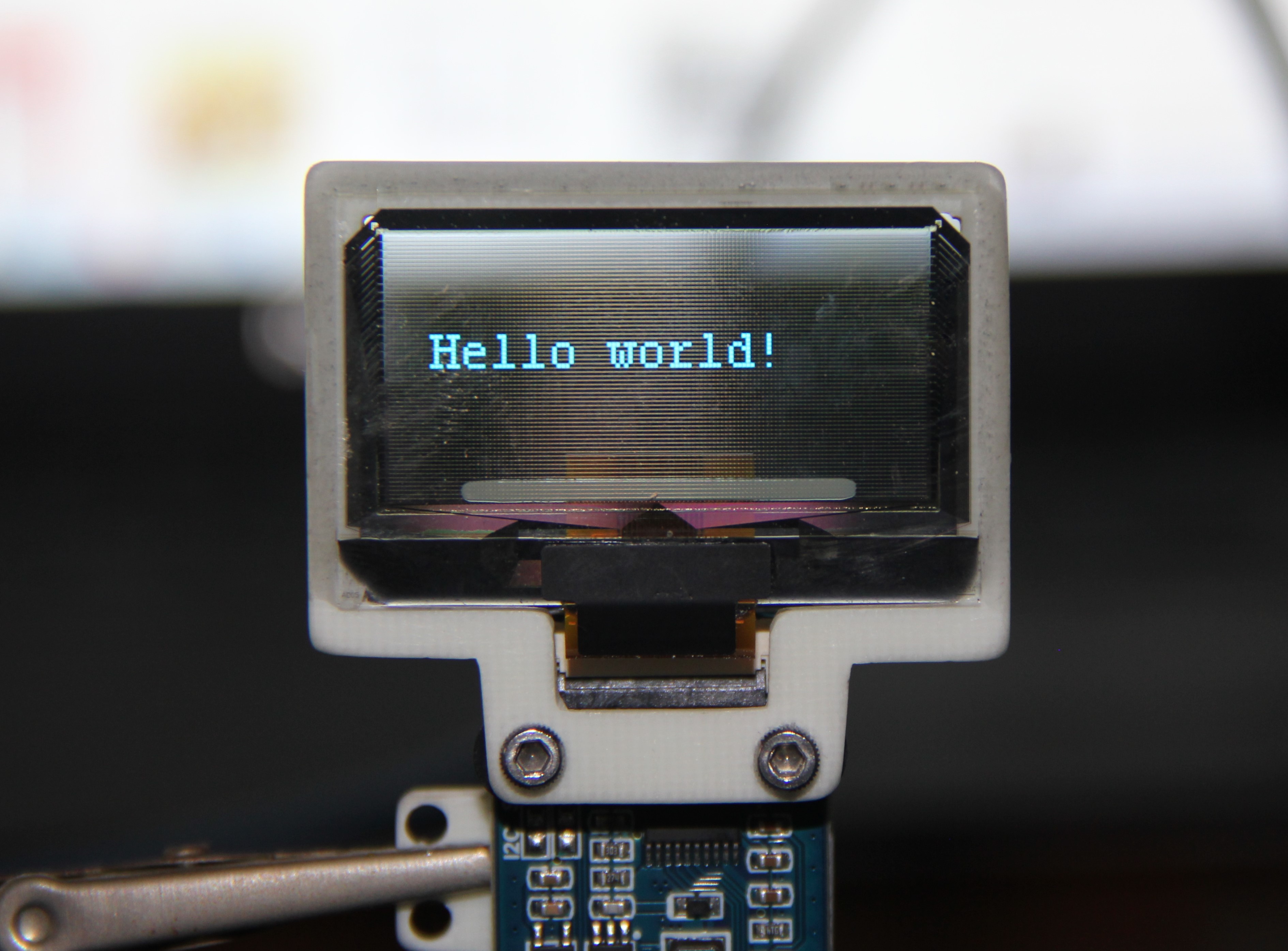
Head-up display
02/25/2023 at 11:27 • 0 commentsAs a head-up display, I use a 1.51-inch transparent OLED, with a 128×64 resolution and SPI/I2C interfaces. I drew the mounts in Inkscape, printed them out, spray-glued them to a 3mm thick GRP board, and sawed them out with a scroll saw.
![]()
Enhancer mask
The mask of the future that turns anyone who wears it into a cyborg.