 Steve
Steve-
13D Printing
The files are here and on Thingiverse(https://www.thingiverse.com/thing:5877289), you might need to make some adjustments, if you use other parts than I did, because some of them i had laying around or bought at a local dollar store(mainly the powerbank)
I recommend printing with PLA 0.24 Layerheight and 15% infill, but it is also okay to use up to 0.32 layer height and 10% Infill for shorter printing time. But be sure to use support.
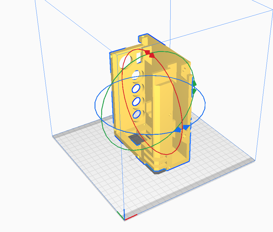
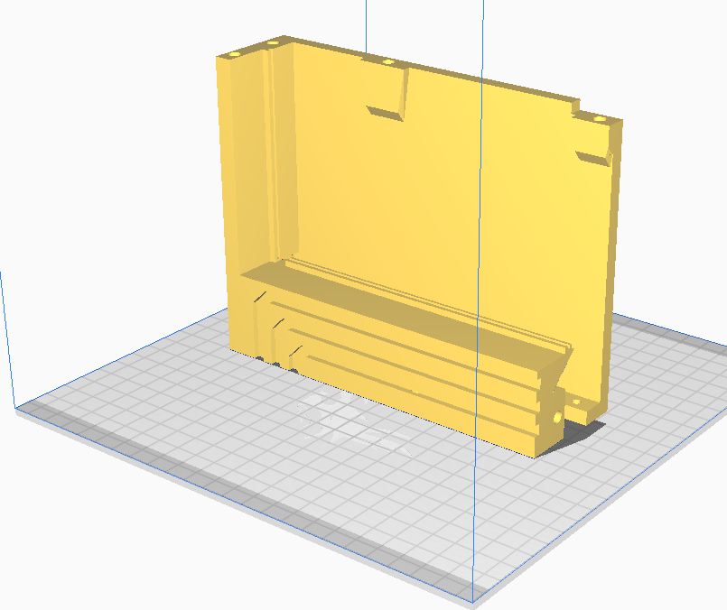
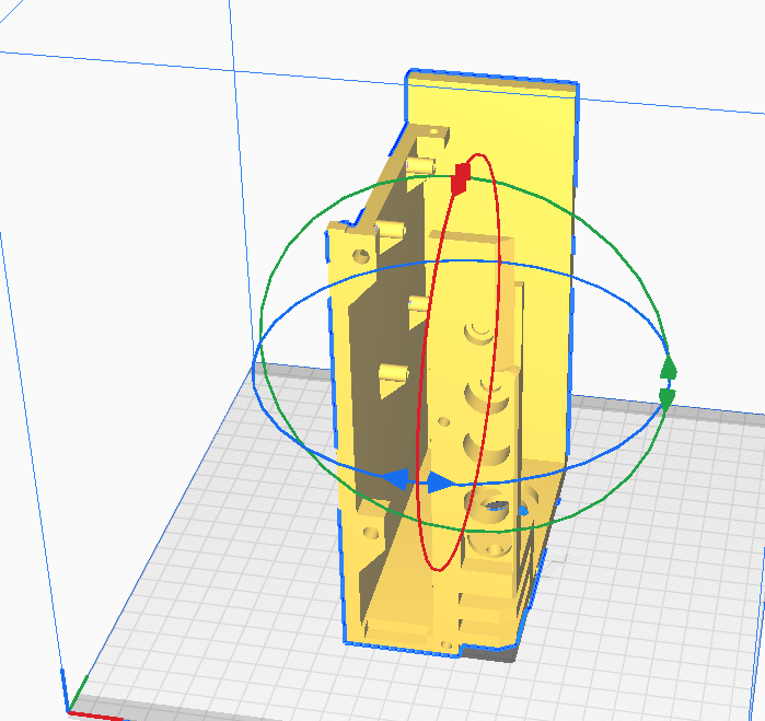
The files should already be alliend for optimal print orientation. All but the following pictures are the plates that can just lay flat, and these need to be placed like this:
![]()
![]()
![]()
![]()
![]()
![]()
-
2Assembly
Now pressfit the screw inserts with a soldering iron. The insets and screw holes are always a pair of a 4mm and a 5.6 mm hole. the 5.6 one is for the insets. Screw the main body and front body parts aswell as the screen lid together with M4 16/20mm screws. it should look like this:
![]()
![]()
-
3Attach the main parts
I put all the parts I used in the Partlist and for some more specific I added Amazon links for you to either buy or atleast get an idea what the dimensions of the parts are.
Screw in the screen with M3 20 mm screws and lock nuts in the lid. The same for the Pi, use 4x M3 10mm screw in the four holes in the right main body part. and screw or glue the dissasembled powerbank in the left main body part(BUT BEFORE THAT: solder two wires, one to the 5V and the other to ground on the usb plug of the board). Use hot glue to secure the OLED and Speaker in the right lid part.
Continue with the USB and LAN ports, the XLR, DSUB, potentiometer of the Amp, Headphone Jack, Power switches, Power light and Keyswitch as seen in the pictures:
![]()
![]()
![]()
![]()
Important: The screw holes for the XLR, USB, LAN and DSUB plug need to be either drilled(DSUB and LAN) or tapped(USB and XLR) for them just drill a smaller than screw hole and drive the screw in, that should be enough to hold it in place.
-
4Soldering
Solder the wire of the 5V of the powerbank to the key switch and from the other pole of the switch connect both the Pi and Display power switches COM cable. tape the NC cable to prevent shorts and connect the plus and NO cables of either switch and the minus to the Ground of the powerbank. The powerbanks ground goes to the PI and then connect the switches NO cable to either the Display and the PI
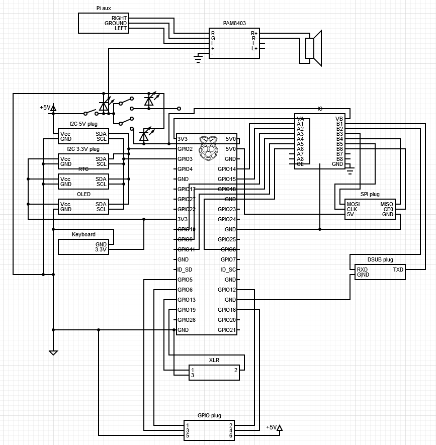
Here is a crude circuit diagramm for the rest and a more precise connection:
![]()
To connect to the GPIO pins use the Jumper cable but cutting them in half an soldering the open end to the plugs, etc, or connect the RTC and OLED with the uncut jumper cables.
Optionaly connect the 5V fan to either the Pis GPIO Fan pins(for temperature control) or directly the the 5V Pins.
-
5Finishing up
Slide the keyboard in and screw the fan with M4 30mm screws and nuts in and lastly screw on the plates with M4 10mm screws and the side panel with M4 20mm screws and M4 nuts.
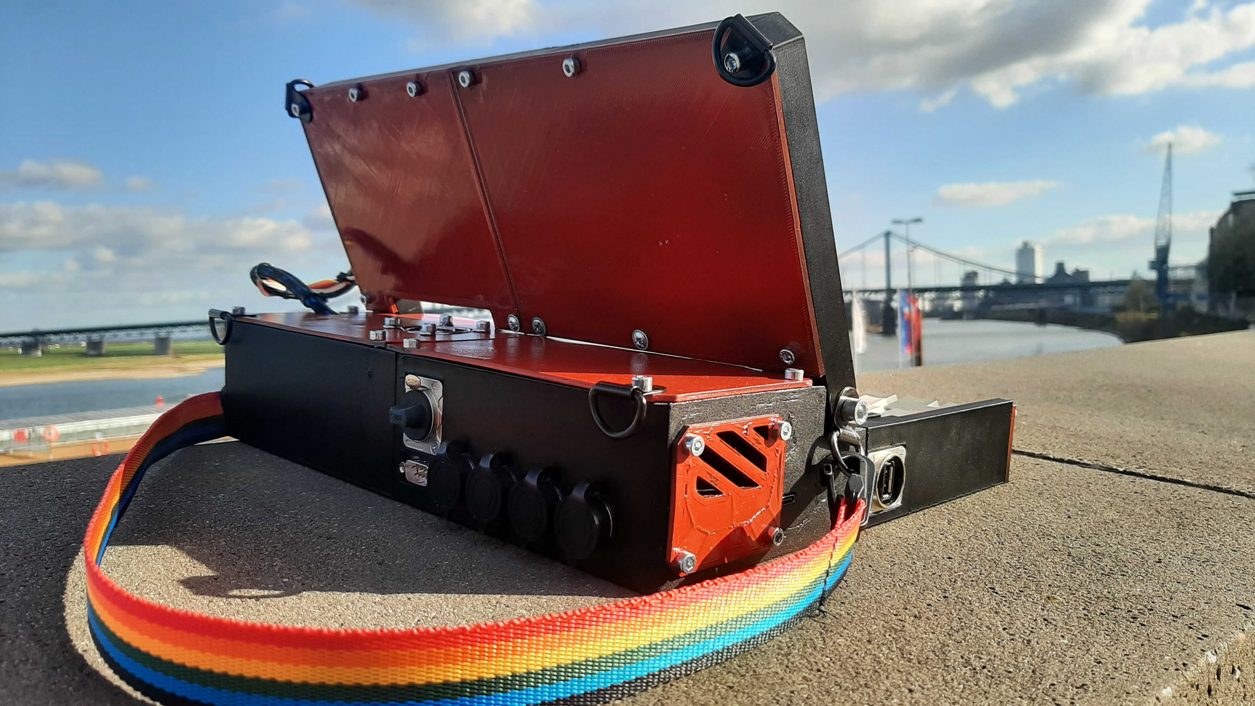
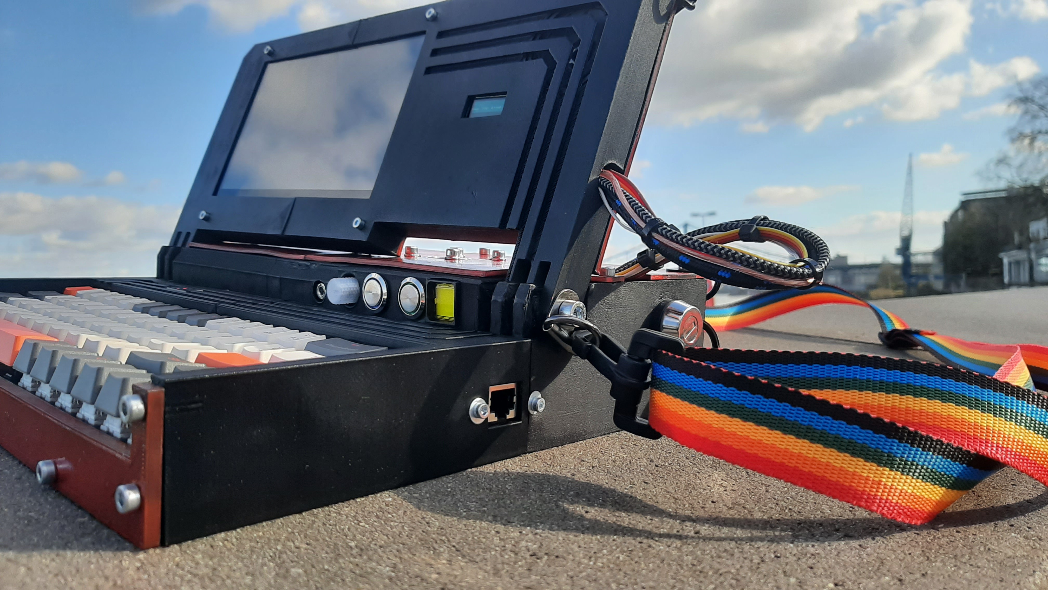
PUC: Personal Utility Cyberdeck
PUC is a simple but versatile portable Computer. Running on a Raspberry Pi 3, it has all you need from a simple serial plug, to I2C and SPI.


Discussions
Become a Hackaday.io Member
Create an account to leave a comment. Already have an account? Log In.