-
Fiber optic Test
08/18/2023 at 22:46 • 0 commentsFiber optic Test
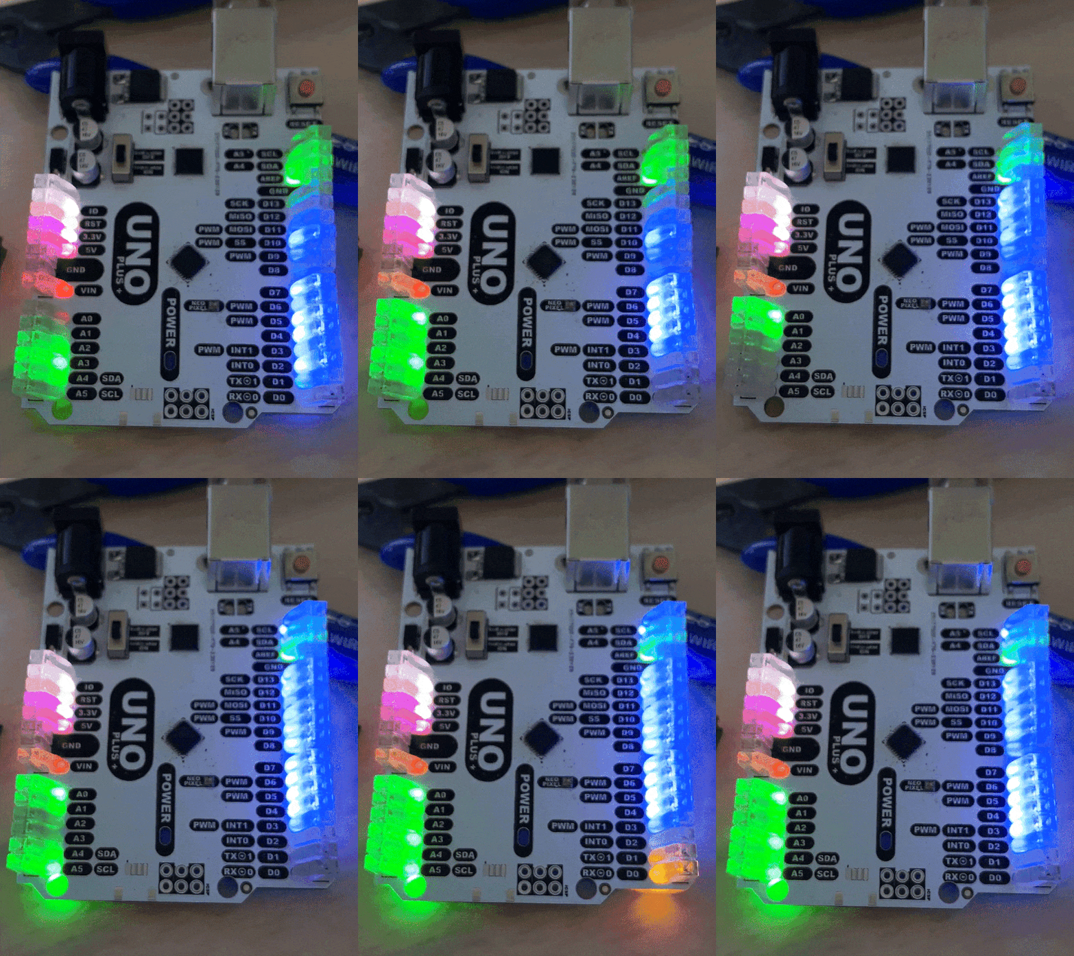
Thank you James Newton For the Suggestion. Adding a fiber optic cable just might work. I used a PMMA Side emission cable an the results seem promising
-
Glowing Headers
04/27/2023 at 20:03 • 0 commentsLED indicators are one thing But if we make the whole header glow the ease of identifying the right pin becomes greater for entry level users
![]()
-
Analog input LED
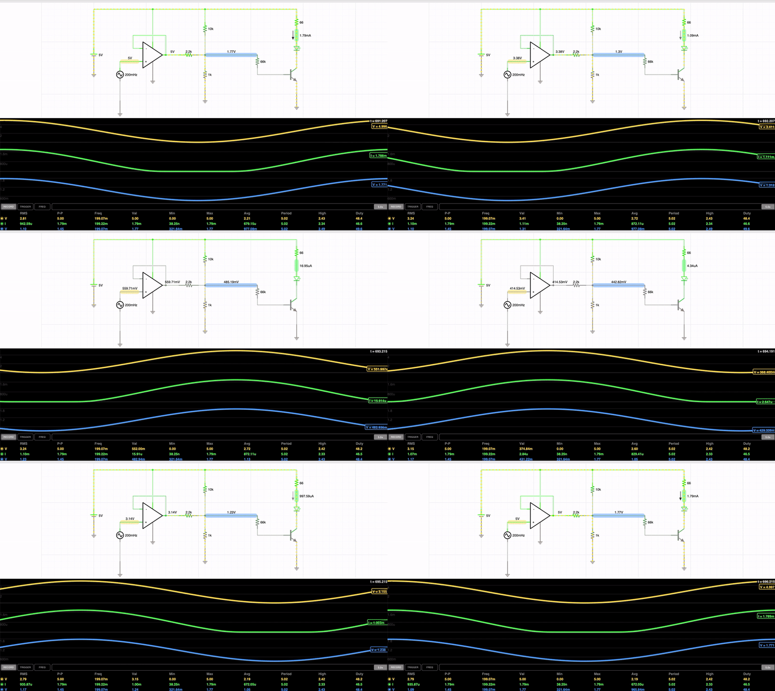
04/25/2023 at 02:57 • 0 commentsUnlike the Digital IO pins the analog pins have an led driven by an Opamp and Summation circuit that will map the LED to the Voltage. So the LED will glow with the intensity proportional to the Voltage 0-5V
The Analog LED Circuit is as Follows
![]()
The Opamp Acts as a high impotence buffer So it does not influence any analog input to the pin. A Summation Network is crated to lower the voltage before it gets fed through a 66k Resistor then into a NPN Transistor to drive the Current to the LED
---------------------------------------------------------------------------------------------------------------------------------------------
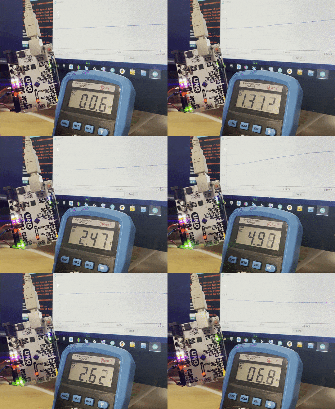
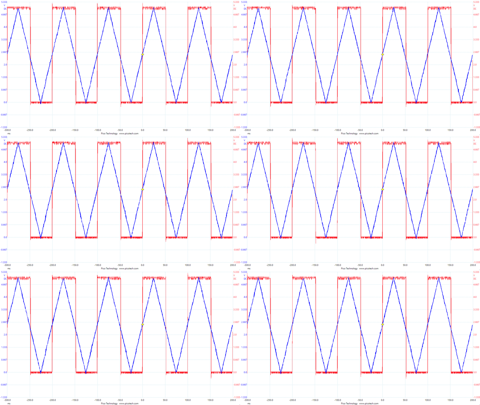
The Real World Test of this circuit show that the current configuration does a decent job of making the pins Voltage to the Intensity of the LED.
![]()
-
Schmitt Trigger
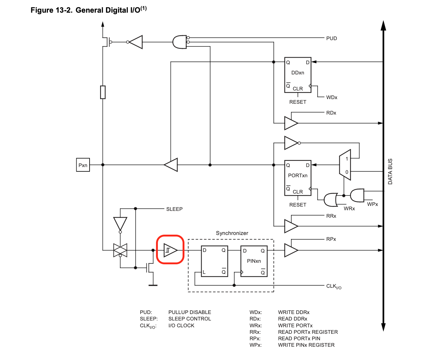
04/01/2023 at 03:54 • 0 commentsThe Atmega328P Has an internal schmitt trigger on all Digital IO Pins. The Schmitt trigger is a great way to reject the Noise of a Digital Pin Especially one that is Left Floating. In addition adding a Comparator to the LED Circuit isolates the pin due to the high input impedance of the Comparator.
However the ATmega 328P does not Express the hysteresis of the Low and High Logic Level.
![]()
So the People over at RadishLogic Ran the 328P Pins.
![Radishlogic - Schmitt Trigger Test Radishlogic - Schmitt Trigger Test]()
https://www.radishlogic.com/arduino/arduino-uno-schmitt-trigger-voltage-levels/ RadishLogic Found that when using USB Buss as the Power the Low High Logic Levels were
![Logic Levels Logic Levels]()
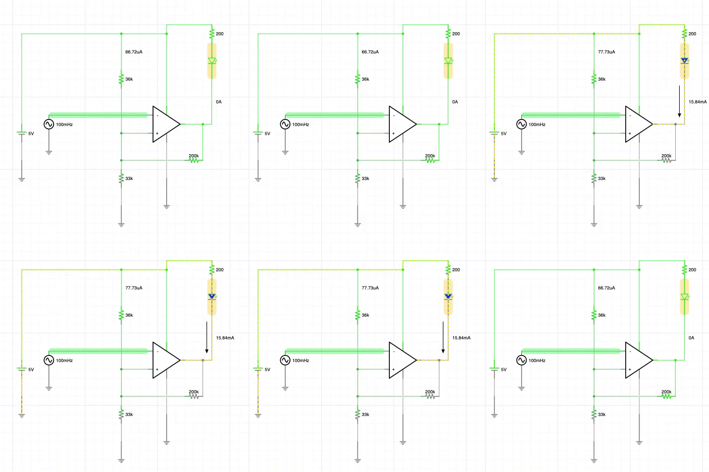
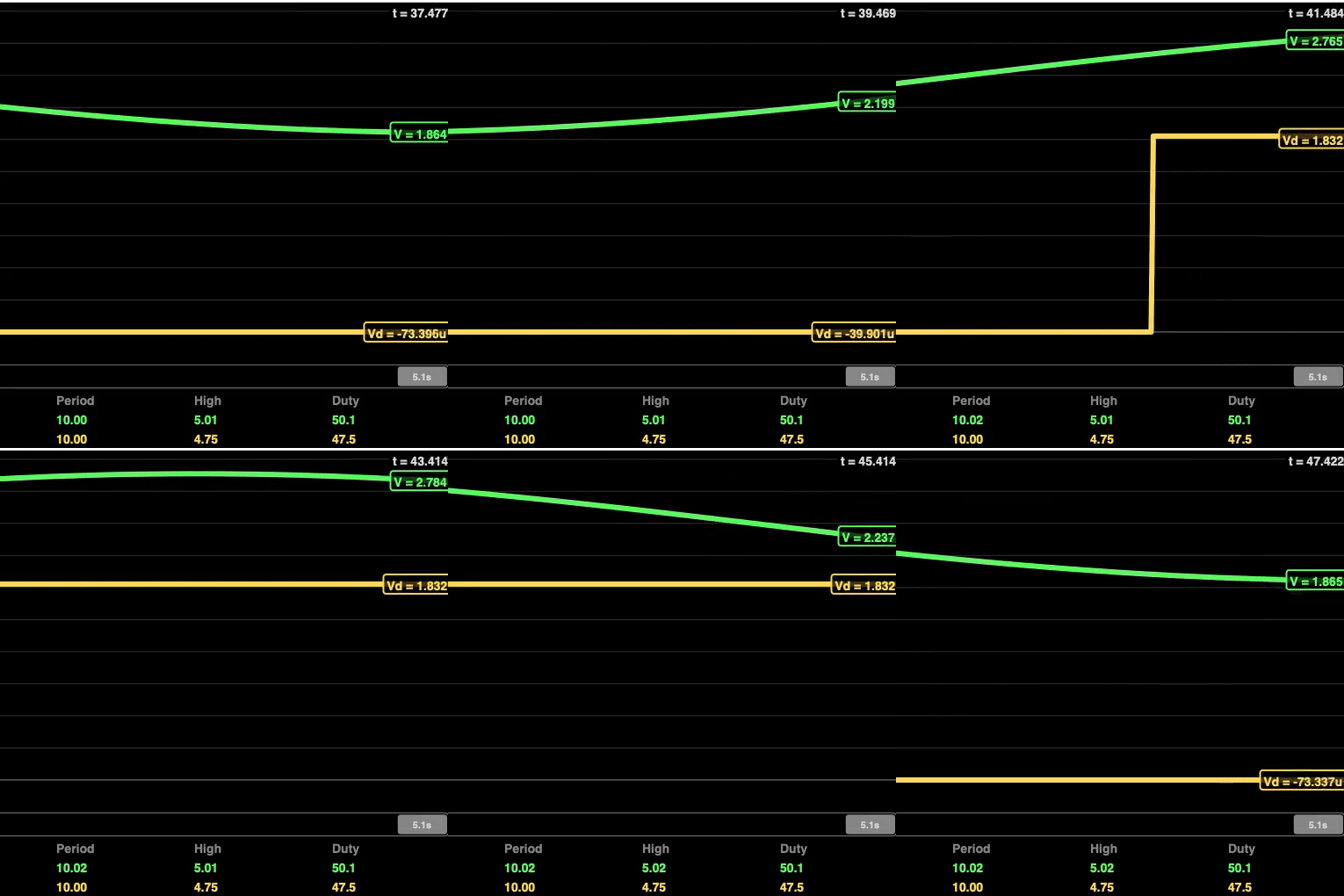
Using 33k, 36k, and 150k a comparable Schmitt Trigger can Be Created
Further Testing on PCB Should be conducted to alpine the Schmitt Trigger of Atmega328 to the LED Comparator
![]()
![]()
---------------------------------------------------------------------------------------------------------------------------------------------------
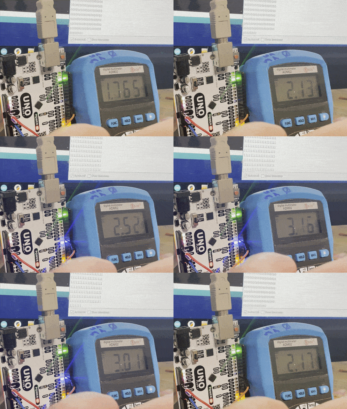
Implementing into the Arduino Plus+ Pin seven is set to digital IO and a modified Button Sketch is used.![]()
So the real world test of the Schmitt trigger show that
1) The LED Low input State Triggers at 2.29V ------ At Atmega Triggers at 2.44V --- 2.23% error
2) The LED High Input State triggers as 2.52V ------ At Atmega Triggers at 2.52V --- 0% error
-
Goals
04/01/2023 at 03:45 • 0 commentsThe Goal of this Project is to Crate a STEM Oriented Using the Microcontroller that started It all.
Features1)The Core of this Will Be an Arduino Uno with the 16U2 USB Uart.
2) Every Pin will have a LED Attached to it to show the Status.
3) ALL LEDs will be isolated using A Follower Op-amp and Comparitor circuit.
4) Digital IO Pin LEDs will be Equipped with a Schmitt Trigger that is close to the internal Schmiit Trigger in the Atmega328P
5) Analog Pin LEDs Will illuminate proportionate to the Voltage of the Pin (0V=off, 2V=2mV, 5V=5mV)
6) A Toggle Switch to turn all LEDs Off
7) The LEDs will Be Reverse Mount and Diffused with Epoxy
8) Placing All components on Bottom allows For ample Space to Label all Pins with all Functions.
9) Electronics will be coated in Epoxy to be more STEM Friendly ( Drops, Spills...)
10) Design for Manufacture
Extras
1) STEMMA/QWIIC Connector
2) Neopixel on Pin 6
3) RTC
4) SD Card
5) Speaker
6) Full Color Silkscreen for ease of pin identification
Uno Plus+
An Arduino UNO Compatible Board with isolated Glowing headers and some Extras
 John Loeffler