Jerry Biehler
-
E-beam power supply
08/14/2015 at 06:50 • 0 commentsThe biggest issue to getting this thing working has been the Electron Beam Gun power supply. This gun wants 10kv at up to 1.2amps to run it, thats 12KW! Not easy to do. I looked at trying to modify other stuff like ion pump power supplies, built voltage multipliers for lower voltage transformer to get the voltage, stack microwave oven transformers in series to get the voltage. Nothing sounded appealing. Ion pump supplies tend to top off around 6kv, multipliers for the kind of current I am looking at would need huge capacitors, and microwave oven transformers.... well, people have reported them working well in series when you isolate them but I just have a hard time believing I would be able to sustain the amount of current I need out of one.
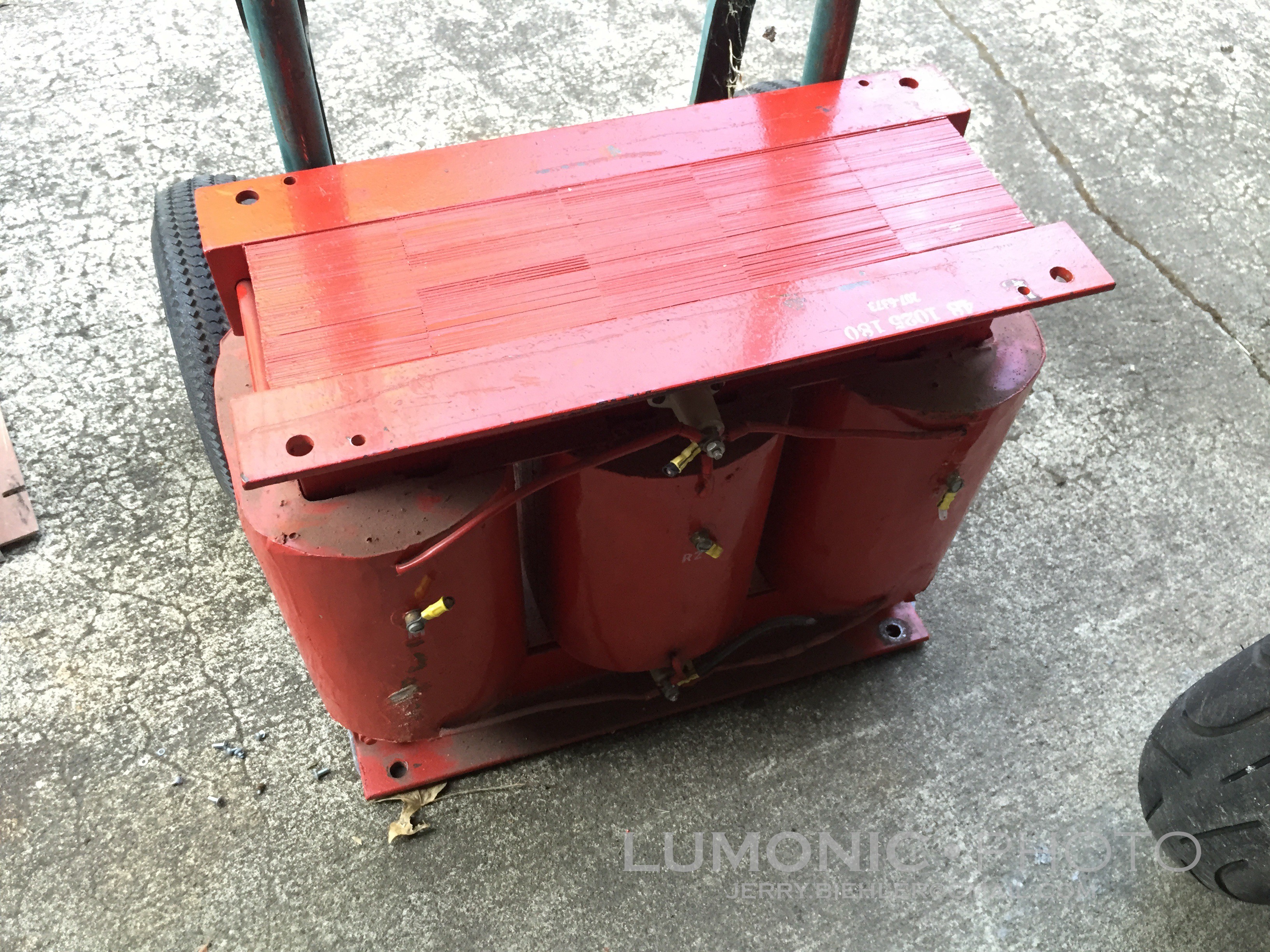
Eventually on ebay a guy listed a couple of old Airco Temescal CV-14 chassis that had been parted out and mostly gutted. But the transformers were still there! He was in the sacramento area so I made a deal with him for $280 and drove down and picked them up. My poor Ford Ranger! These transformer are HEAVY! 305lbs each! Plus all the other stuff that came with it, the chassis themselves and all sorts of used parts from these machines. And most importantly, a bunch of the same type of relay that was used in the Flux Capacitor prop in Back to the Future. I can probably get $100 a piece for these so that should cover the trip alone.
![]()
What a beast! Delta 208-240 3 phase in, Wye HV out with shielding between the primaries and secondaries. The idea is to drive the transformer from a Variable Frequency Drive, these devices are used to drive three phase motors at variable speeds by rectifying incoming power and then recreating the three phases with internal power transistors or IGBTs. Since they rectify the incoming line power they will often run on single phase so they are good options when you want to run a three phase machine tool at home.
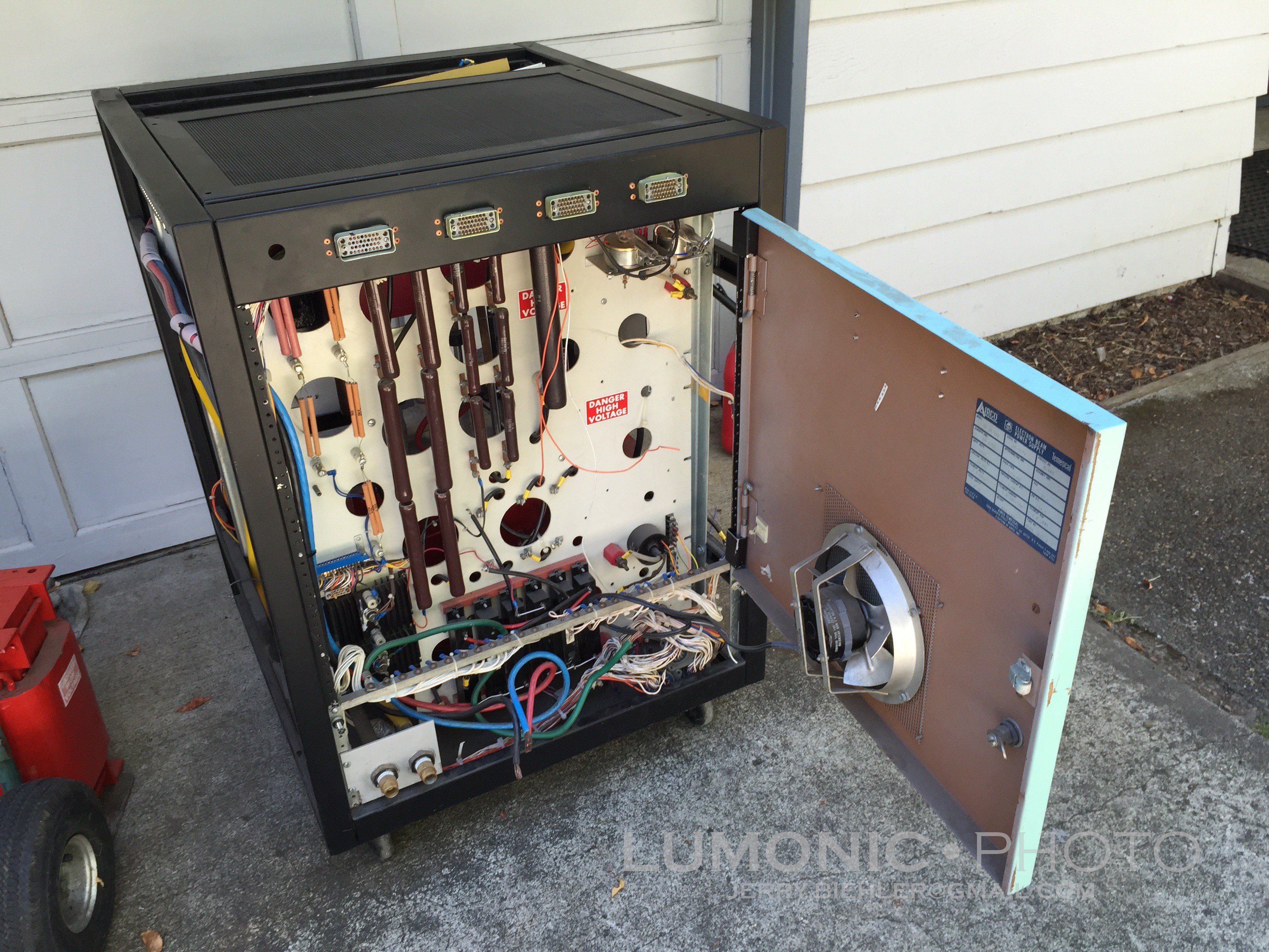
So to test the theory. First thing to do was to rewire the chassis back to stock. Between all of the parts I had I had just about everything to put the HV DC section of the power supply back together. I found the schematics online which made things a whole lot easier.
![]()
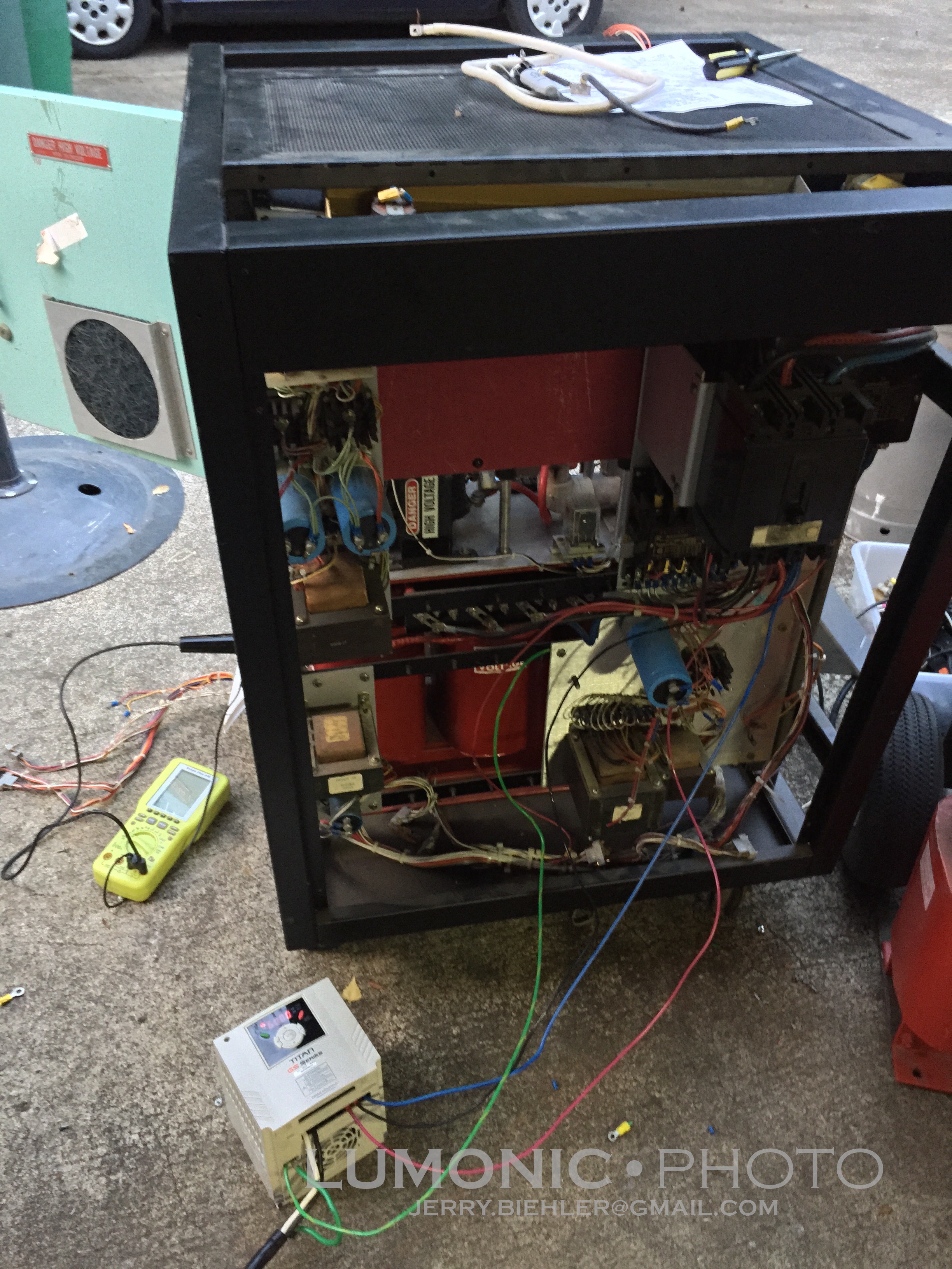
Once everything was rewired on that side I spliced in a 3HP Cerus Industrial VFD I had to the circuit breaker that feeds the HV transformer. I set it to V/HZ mode, no acceleration or deceleration, 240v out, and 60hz. I hooked a HV probe of a battery powered scope to the output terminals and hit the start button on the drive. It worked! Kinda, it was drawing a lot of current according to the internal ammeter on the VFD, something like 22A. Considering the drive is rated for 3HP, about 11 amps, it shut down pretty quickly. I increased the PWM frequency from 10khz to 15khz in the parameters and the transformer was much happier, only drawing 6 amps. It still shut down the drive after about 30 seconds but it was a good proof of concept test.
![]()
But I hit a problem. The most I could get out was 9.5kvdc. It was pretty stable at around +/-50v but thats with very little load. Once it gets loaded the voltage is almost certainly going to drop. In the original design the HVDC side came to 12.5kv after regulation. The positive leg ran into a water cooled triode, a Eimac 3CX20000A7, the 8KW sister version used a smaller air cooled 3CX10000A7. A pretty simple circuit drives the grid to regulate the voltage. The tube is gone but the base, filament transformer and the rest are there. So the thought was find a used tube to put back in there. Yeah... Easier said than done. Virtually nothing on ebay, what is there is around $1600. Ouch!
Another option was to build a cascode series of mosfets to replace the tube. I have a mass amount of them but the actually current handling capability at 1200v, what they are rated for, is pathetic so that idea died. Even if I did get it working I would have to figure out a drive for the filament transformer for the gun. Emission current of the electron beam is controlled through the temperature of the filament, the hotter it is the easier it is to emit electrons and the high beam current.
After all that I pretty much scrapped the idea of making one of these power supplies work. Instead I found another complete Thermionics 15kw power supply on ebay and the matching control box from another company. $500 for the power supply and $275 for the control box plus shipping which will probably run me about $2-250 on the power supply and about $50 for the control box. Ill figure out how to drive it later. I might just try to run it off a 15hp rotary phase converter I built years ago.
Now to figure out what to do with these transformers. Seems a waste to scrap them, I can rewire the primaries and make it single phase transformer. If I parallel the outputs I can get the full 10kv at 1.5 amps. I might be able to series the secondaries and get 30kv at 500ma! That would make one hell of a bug zapper! Actually these transformers scare the hell out of me....
One serious use might be to build a bombarding transformer for doing neon work, that is something I have always wanted to do. I would need a way to control the current out, it would be pretty easy to build a sliding core inductor to limit primary current. Another option would be to build a mag-amp for the output of the transformer.
So all in all, this part of the project has been a bit of a bust. I won't loose any money off it, in fact I will make some, and I did learn a VFD will drive a transformer without freaking out. I also may or may not have fried my HV probe, I dont know yet, it arced through the case seam to the chassis of the power supply.
-
Crucible Indexer
08/14/2015 at 06:04 • 0 commentsThe E-beam gun has 4 pockets, they are driven by a bevel geared shaft on one side of the e- beam gun. One turn of this shaft indexes the crucible one position. Initially I was going to use a ferrofluidic feedthrough and a miter gear set to drive the crucible with a motor on the exterior of the chamber. This would really limit the positioning of the e-beam gun to one of just a couple position where there are existing 1" holes in the base plate. Another option would be to drive it with a motor internally but to do this would be pretty expensive. Vacuum rated motors are pretty rare and when you do find them, expensive. I have an octal baseplate feedthrough and only need a couple of the pins for the e-beam sweep magnets so installing something internal would be ideal.
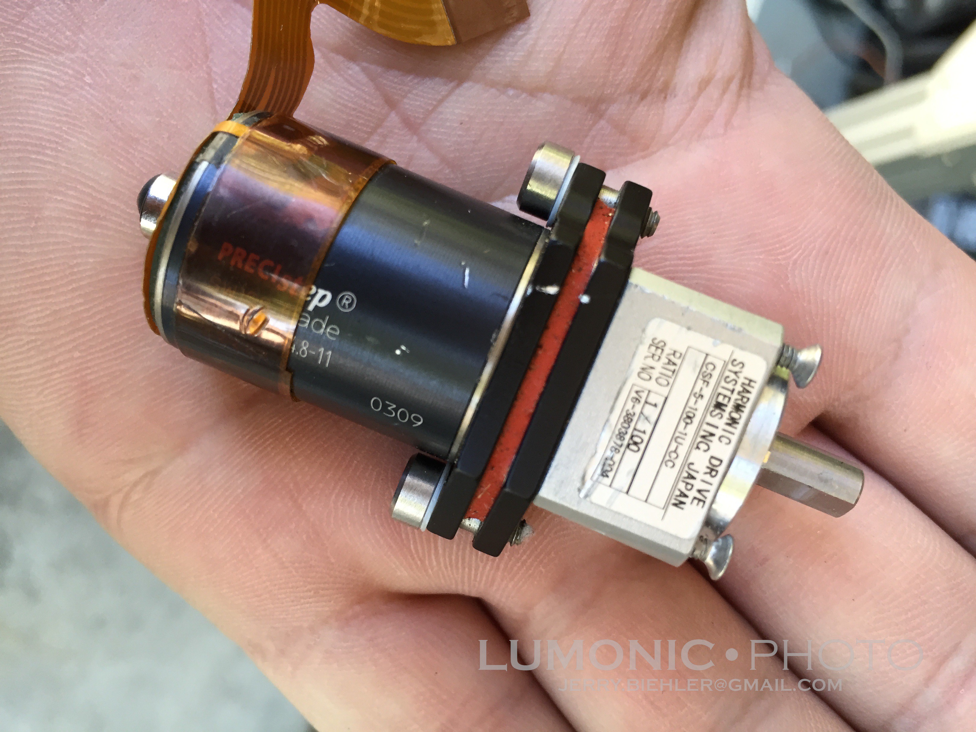
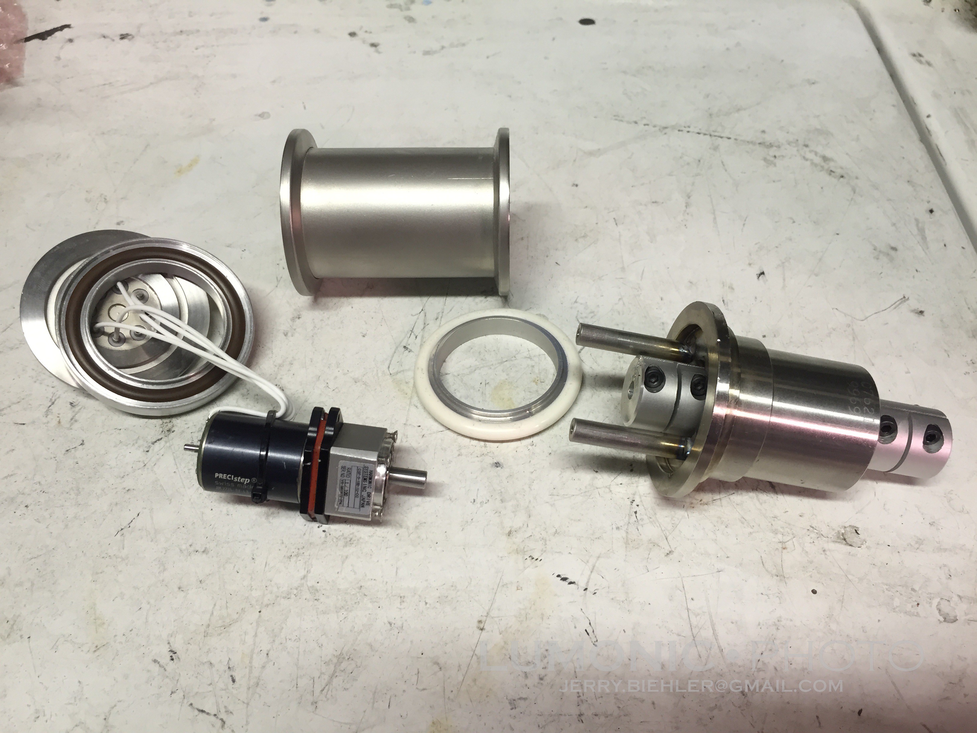
So I made my own internal electrically driven stepper drive indexer. I have had this little stepper motor kicking around for some time, I pulled it out of a wrecked drone camera, it has a 100:1 harmonic gearbox on it. This ought to have enough torque to drive the indexer, there really is no load on it.
![]()
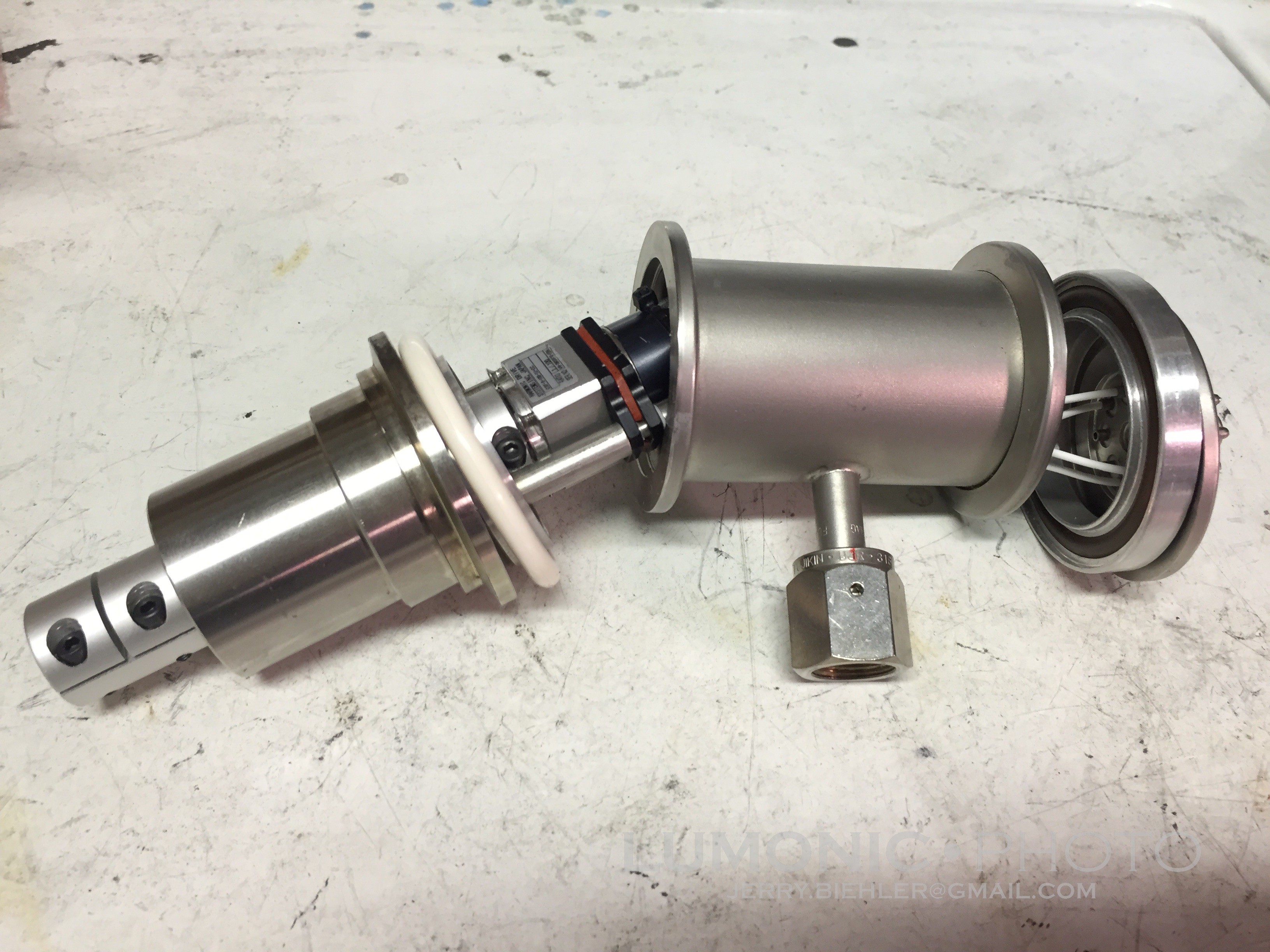
I found I had a small section of KF-40 line with a 1/4" VCR fitting on it, the motor was small enough to fit down the center. I scrounged up an old KF-40 Octal feedthough and a small ferrofluidic feedthrough I had lying around. The feedthrough was tig welded to a bored KF-40 flange and I made a couple stainless standoffs from 1/4" rod scrap to mount to the two screws that hold the stepper to the gearbox. These were tigged into place as well.
![]()
I ordered a couple split clamp style couplings from ebay, a 5-6mm for the motor to feed though and a 6mm-1/4" to drive the gun shaft. I have found it is just not worth the trouble to make my own couplings, they are difficult to get concentric and straight. I did have to shorten the internal coupling down to get enough room to fit everything in the can.
Typically vacuum fittings and seal do not expect to see internal pressure. When they do they need something to support the outside of the o-ring. I did had one KF-40 seal with that, the other seal is some sort of hard white plastic material, it should be hard enough to withstand the internal pressure without blowing out... I hope!
Teflon insulated wires were soldered to the motor terminals and to the octal base pine. If I am going to have a leak anywhere, it will be the base pins, they are hollow with holes in the ends so I hope I got a good seal. A couple KF clamps and a VCR plug on it and it should be good to go. I still need to figure out how to mount it internally, I want to make a saddle to clamp the feedthrough section in place but the Y axis servo drive died in my CNC mill and I need to find another used one.
![]()
-
More fun...
07/25/2015 at 04:33 • 0 commentsI have not updated this in a while. Some of the things I have been working on:
Calibrate the Film Thickness Monitor.
To calibrate the crystal thickness monitor you coat a sample and compare the what the thickness monitor says you coated with what you actually coated. To do this you need something that can measure down to the nm range. There are several ways to do this, an Atomic Force Microscope (AFM), and ellipsometer, and a commercial film thickness monitoring device. Lucky for me I have a friend with an AFM! I took some coverslips and coated them with what the control said was 500 angstroms of the materials that are loaded in the boats. These were then taken to the lab where I scratched the coating to create a sharp edge so the AFM stylus can measure the ridge. These readings are then used to create a "tooling factor" which is entered into the control with other factors like material density to hopefully give me a correct coating thickness.
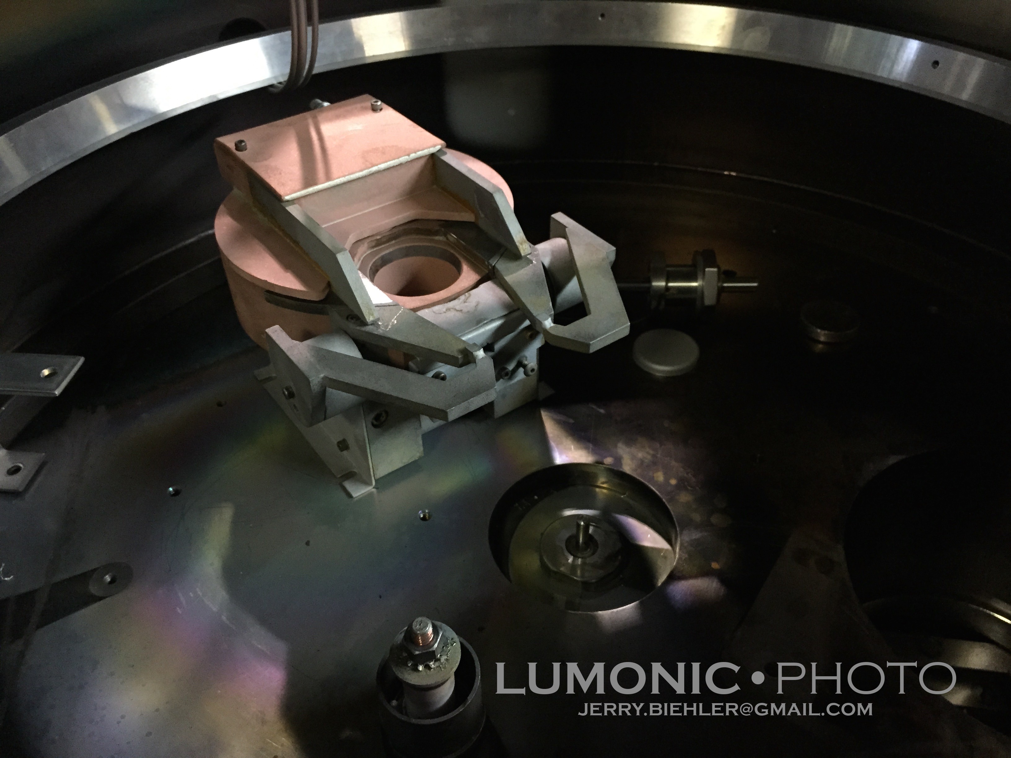
Install a Electron Beam Gun.
There are a lot of materials that just to not thermally evaporate well. To deposit these materials you need to use an electron beam gun which directly heats up the evaporant instead of heating it though a crucible. The most common kind of e-beam gun for thin film deposition is a 270 degree e-beam gun. The electron beam is emitted from a negatively biased heated filament mounted to the side of the e-beam gun. Magnets cause the beam to wrap around 270 degrees to hit the source material from above. This keeps the evaporating material from coating the filament and causing shorts. There are additional electromagnets on the e-beam gun to scan the beam in two axes over the surface of the source material similar to what happens in a CRT.
E-beam guns are incredibly expensive, a new four pocket one is pushing $10,000. And the power supply to drive it is even more expensive. Small e-beam guns run in the 3kw range at 4000v accelerating voltage at up to 750ma beam current. Larger e-beam guns run at 10,000v accelerating voltage at currents up to 1.5 amps. These supplies need to be adjustable in current and voltage, that's why they are so expensive.
I lucked out and found a couple e-beam guns on ebay. The first was a sloan single pocket gun. It is designed to run at 10kv a up to 1.2 amps. It was designed by a company called Sloan and now is made by another company, I believe this one is made by the latter.
![]()
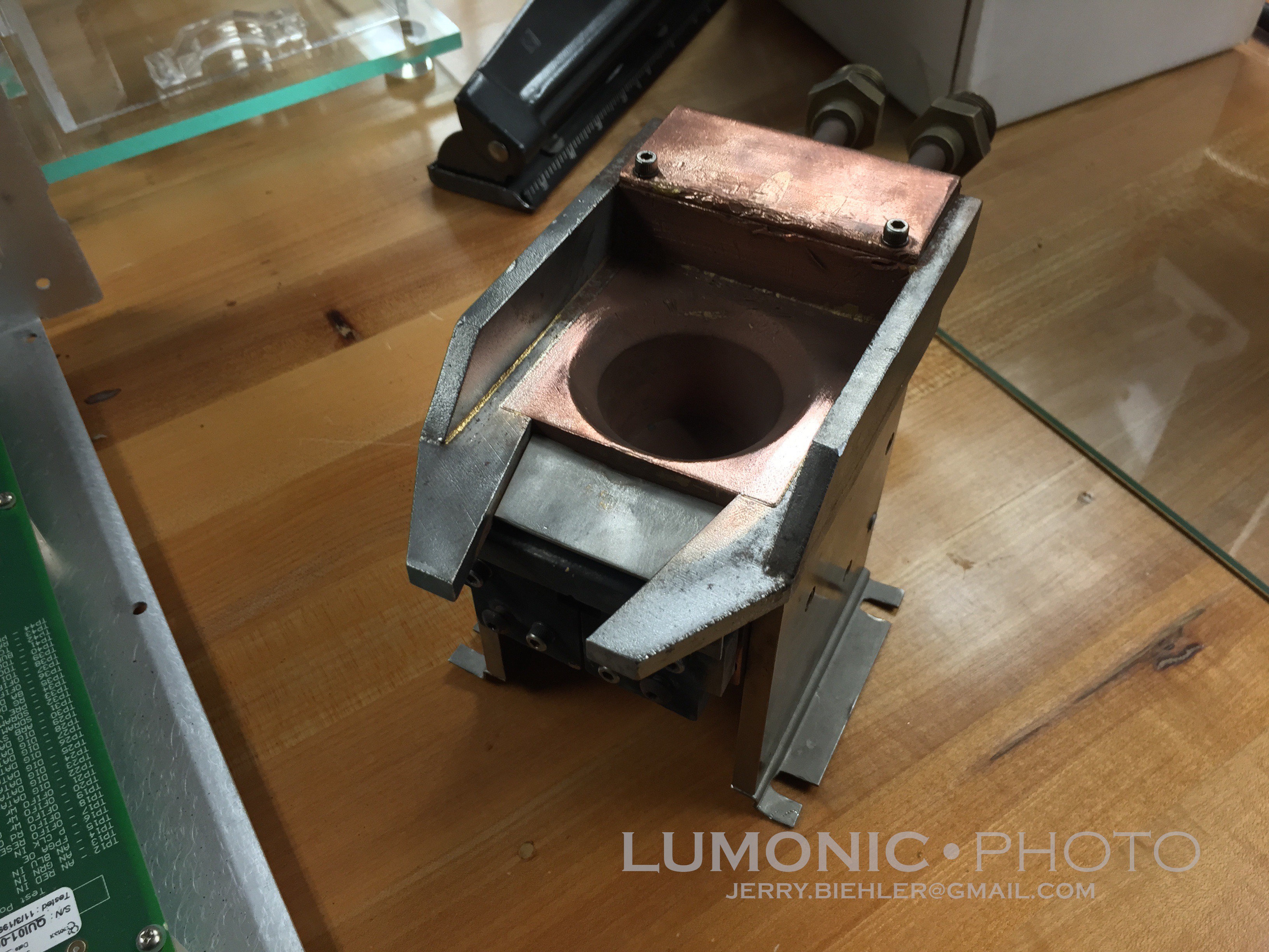
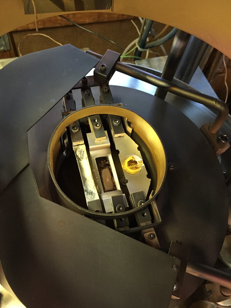
The seller did a awful job packing and several ceramic standoff were broken. It appears it was used to coat gold, traces can be found in the corners of the gun. Having only one pocket would be rater annoying. the plan was to mill out the copper down the center and make a sliding crucible that would allow me to change materials that I wanted to coat. Then I found this guy, a 4 pocket version of the same gun and I got it for $80 plus shipping out of canada. Not bad!
![]()
![]()
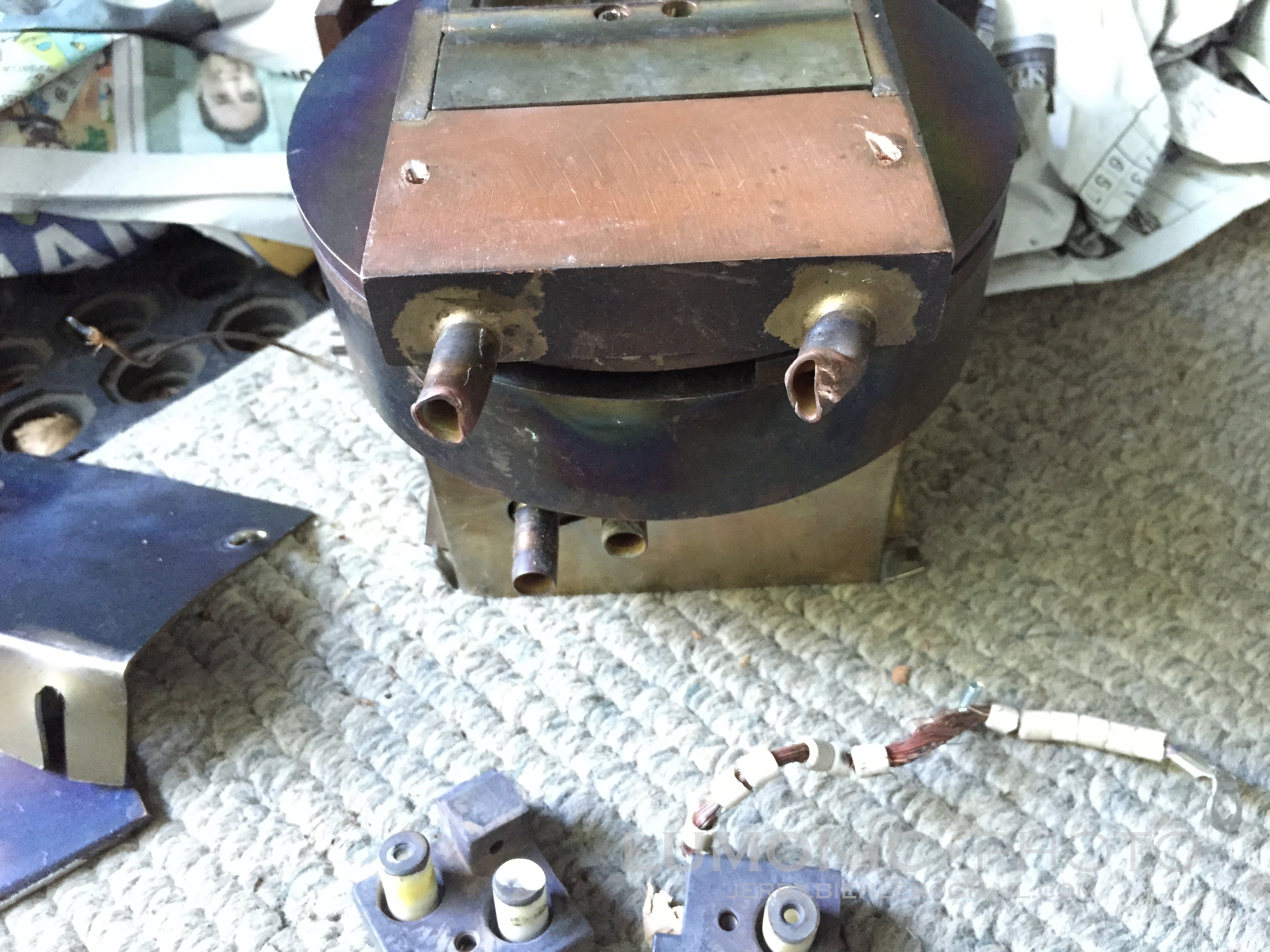
The seller had asked a guy where he worked to pack it up and ship it while he was out of town. He shipped it packed in newspaper! Not a good choice!
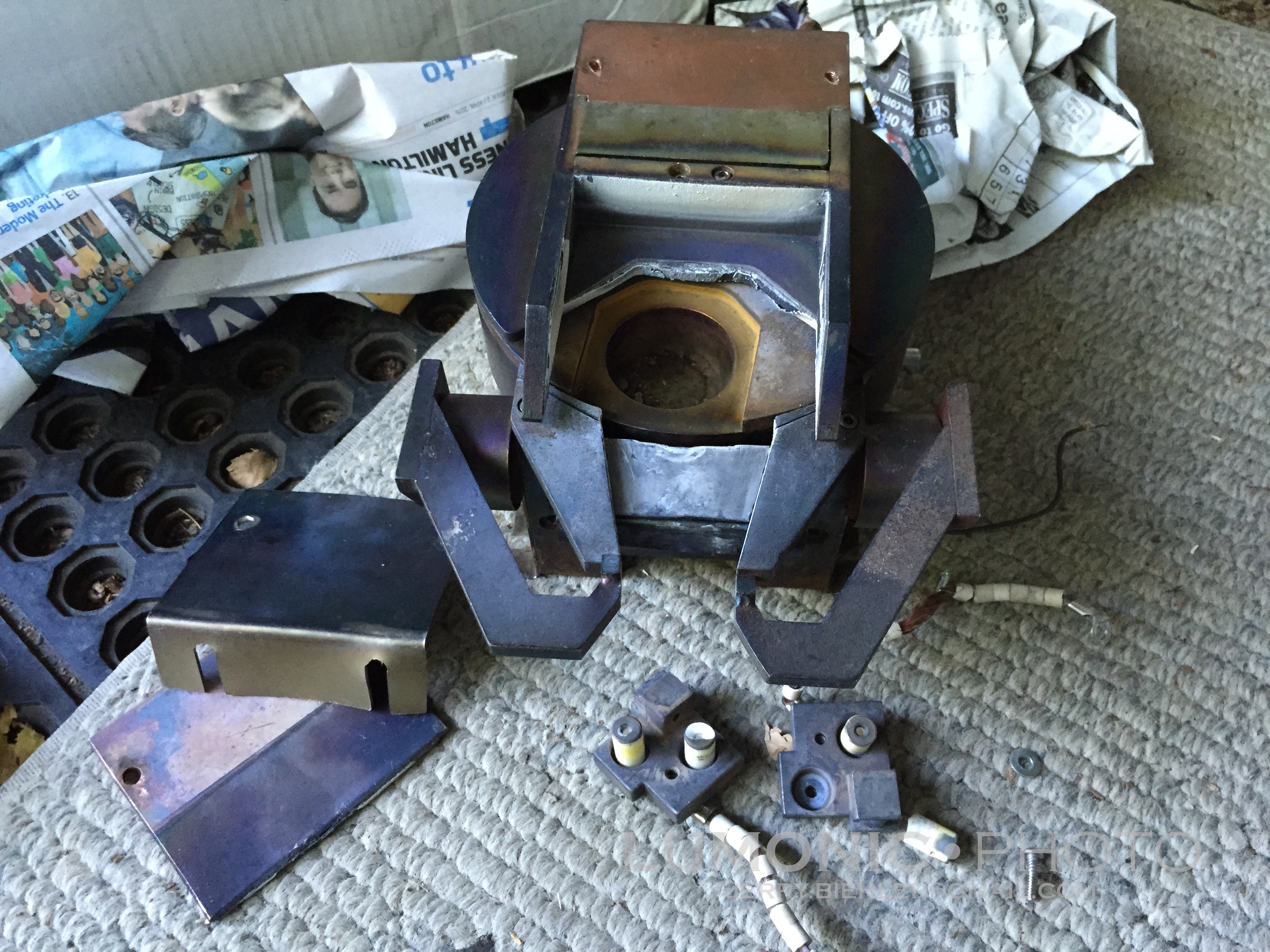
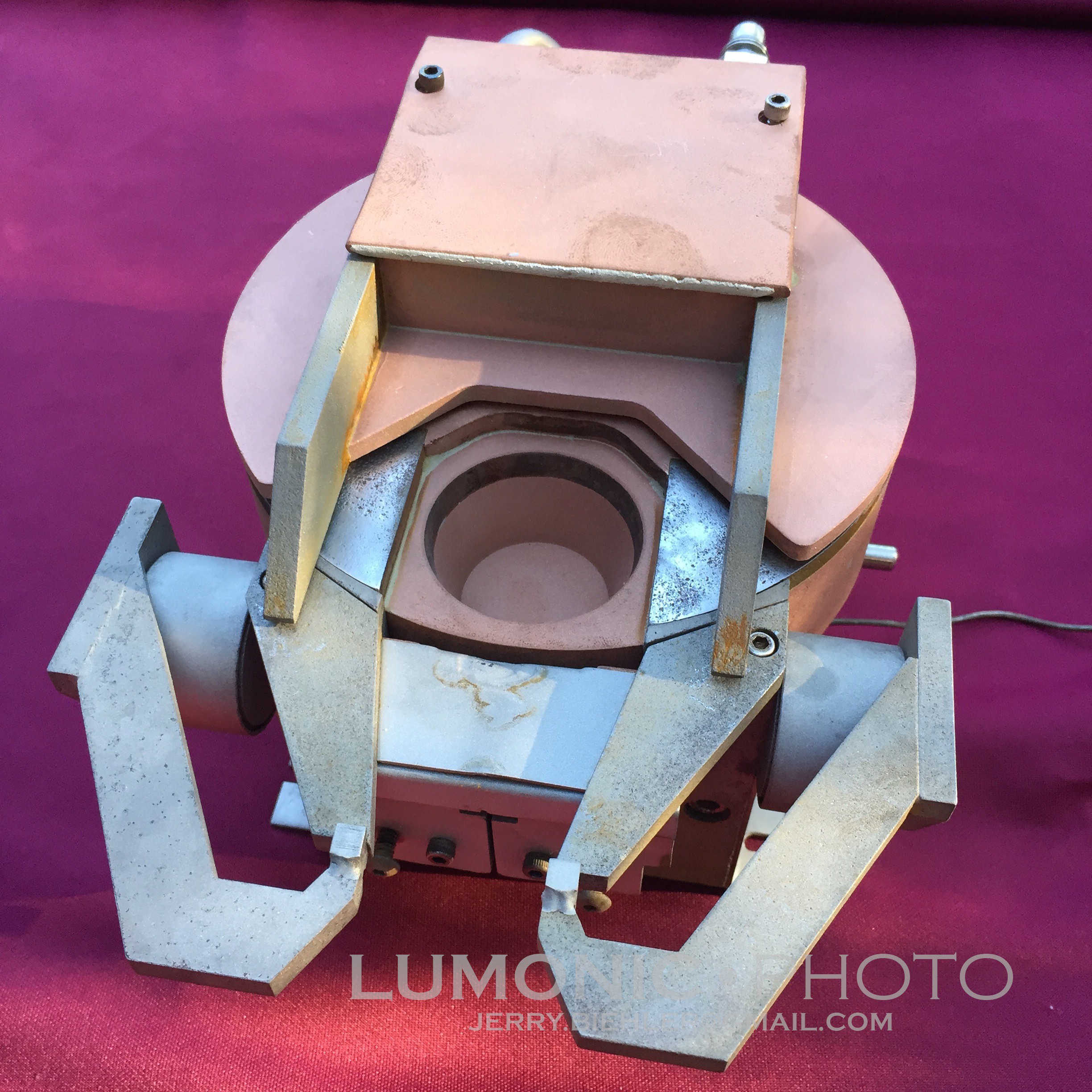
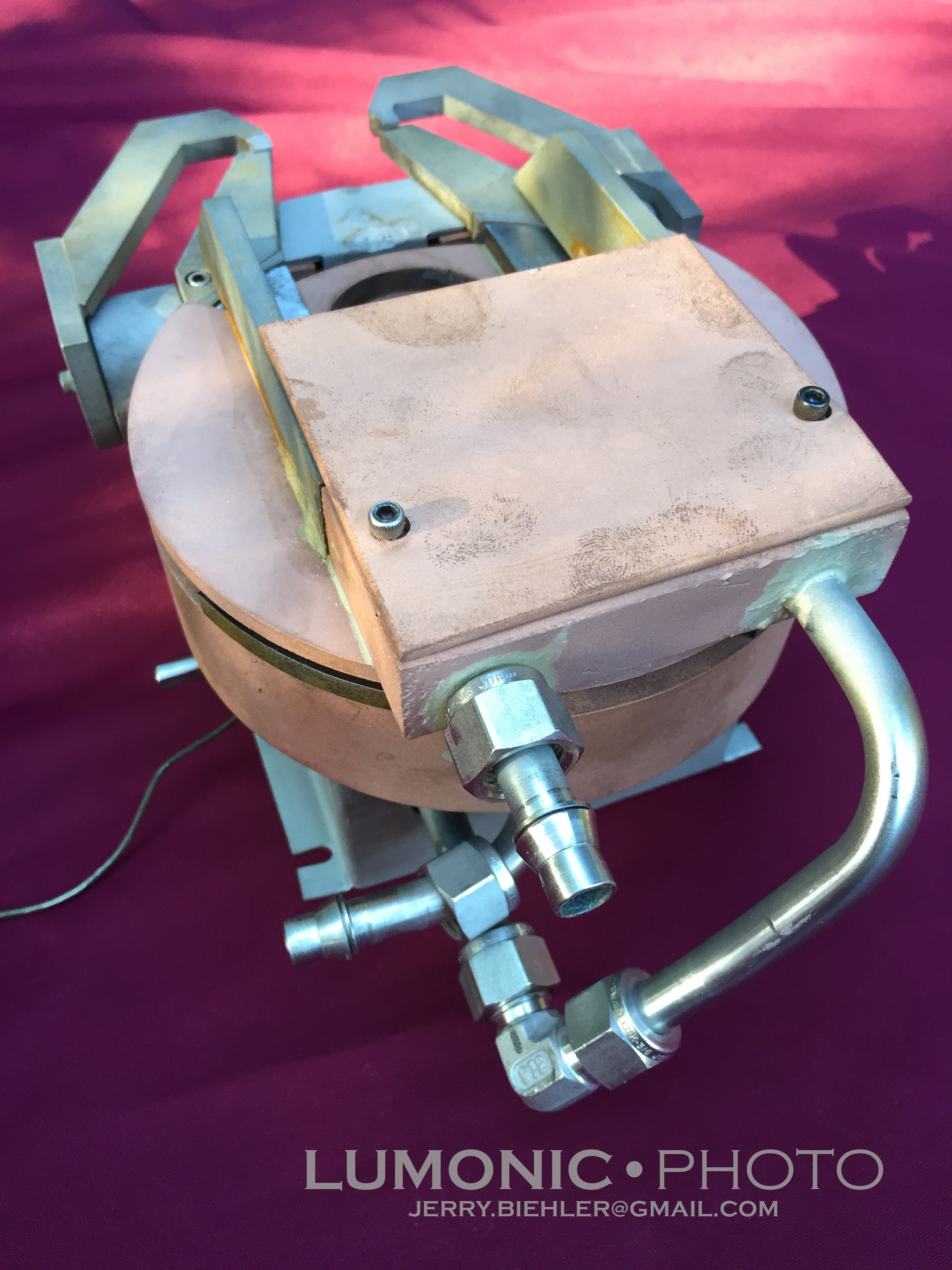
Standoffs were broken, cooling lines were crushed, metal was bent. It was a mess. The seller refunded me the cost of the broken parts ($80) so I basically got it for the price of shipping. I took it apart, replaced the bearing for the index drive, made and replaced a detent roller, straightened out the bent parts, replaced the broken standoffs and brazed in new stainless water cooling lines. Finally I bead blasted the gun and put it back together.
![]()
![]()
![]()
-
First Coating
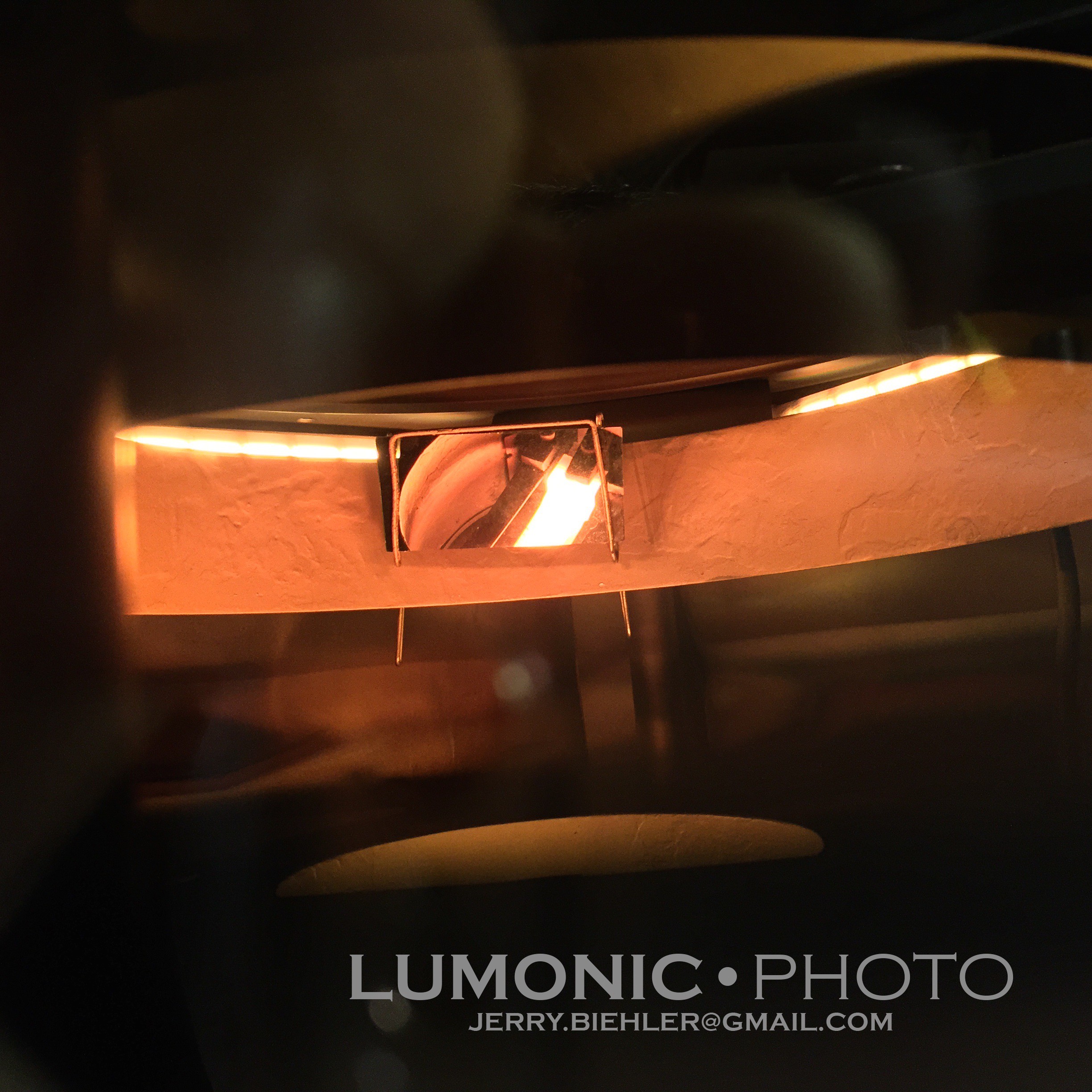
04/27/2015 at 18:13 • 0 commentsCoated a microscope slide with copper last night. Still need to get the film thickness monitor hooked up and the new digital ion gauge controller mounted.
Looking inside the chamber off a mirror at the tungsten boat that holds the copper to be evaporated.
![]()
The coated slide:
![]()
-
New system running...
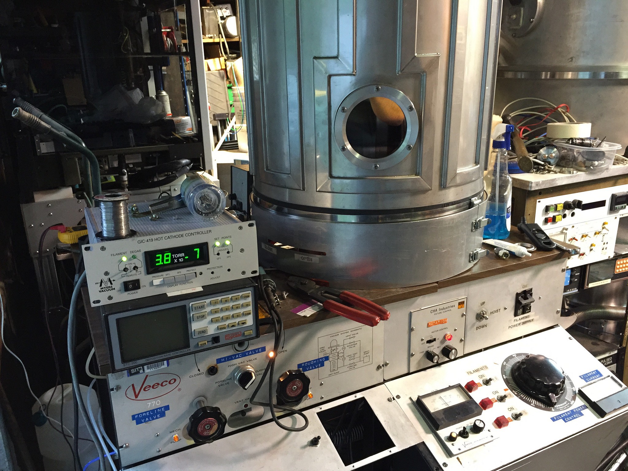
04/23/2015 at 05:46 • 0 commentsDigging though the interwebs I have pretty much figured out this is a Veeco 770 and Cha SE-600 mashup. The base is Veeco, the 19" Jar, lifter, heater control, and planetary system is Cha Industries.
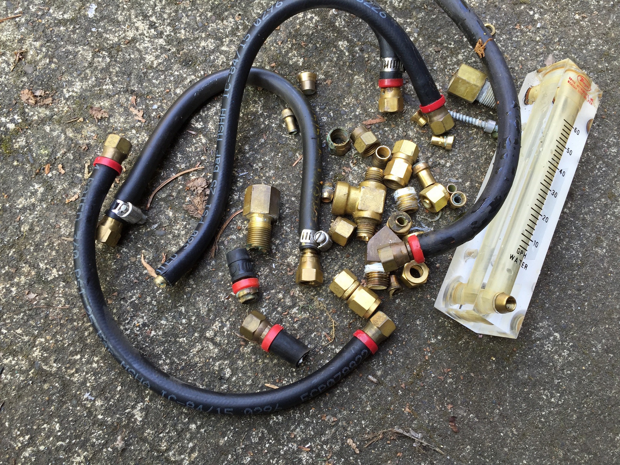
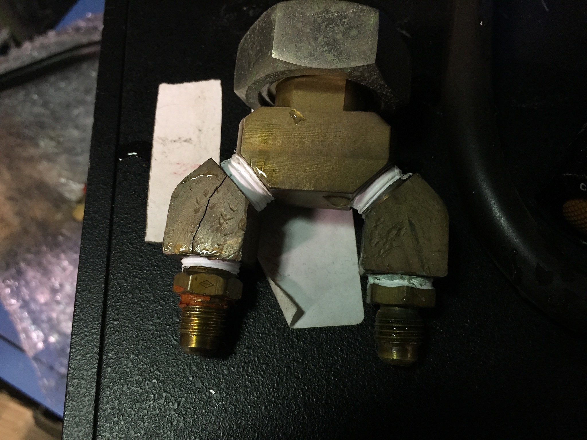
I have spent the past week or so getting this new system running. Ran into a huge problem with the cooling system, the water line feeds the diff pump, the water cooled feedthroughs, the jar, the ferrofluidic rotary feedthrough, and the crystal sensor holder. I had 31 bad brass fittings. Almost every flare fitting had at least one crack down the length of it and some almost crumbled. Swagelok fittings just snapped in half, and ever big heavy brass tees and street 45's had cracks right down the length. Mind you this system has been kept in a heated warehouse so there was no freezing. I really have no idea what caused this, I have never seen brass act like this. My best guess is they were not using RO/DI water in the loop and some sort of electrolysis set in with power running from the water cooled feedthroughs that supply power to the evaporating boats. Its only a couple volts but that could be all it took.
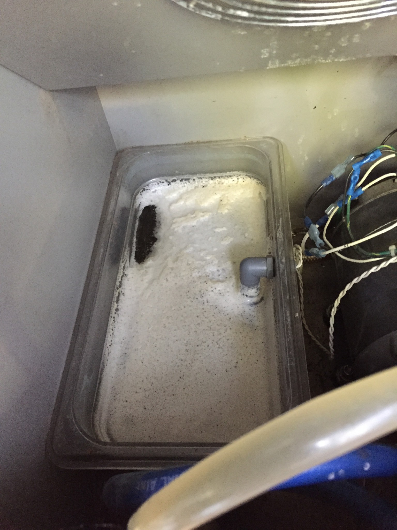
Or it could have been something in the water. The reservoir for the cooler had a layer of foam in it when it first started circulating. I flushed it out and it is now running clean with RO/DI water.
Thats all fixed now and the flow meter got new o-rings as well. Got it down to the low -7 last night, with LN2 in the trap I should be able to get down to the -8. The cooler might be a little small for the pump and system. The lines were starting to get above ambient, I may have to add a secondary radiator.
All of the fittings I replaced, eventually I will section a couple of them and check them out with the SEM and EDX to see of there was a change in the alloy radially through the part:
![]()
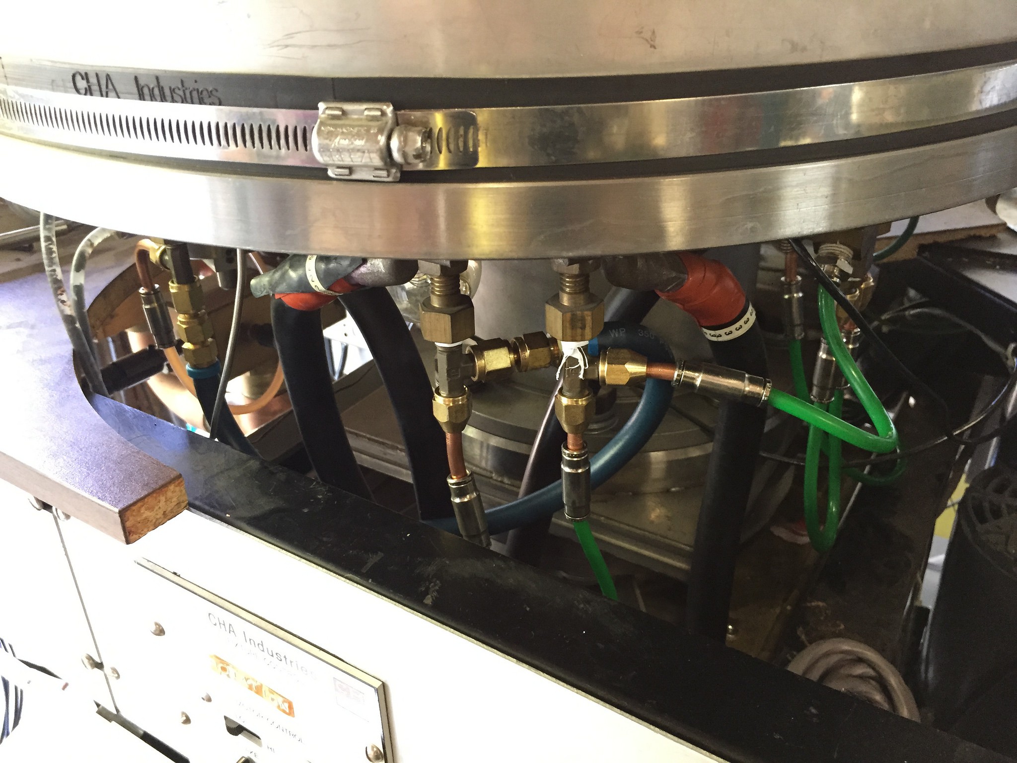
New plumbing for the feedthroughs with copper flares, push on connectors, and polyurethane tubing.
![]()
Foam on the water.
![]()
One of the many split fittings:
![]()
It's alive!
![]()
-
Another System!
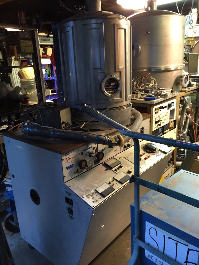
04/10/2015 at 06:44 • 0 commentsKind of got sidetracked on the vacuum system. I got another one!
Some more pics of the new system. This system came from a company called SITe, it was a spinoff company from Tektronix that made top of the line scientific grade CCDs. The Imaging Spectrograph in the Hubble uses one of their CCDs. http://www.stsci.edu/hst/stis/design/detectors/
About 11 years ago the company went under and everything went into storage. One of the items was this coater still bearing old tektronix tags. They finally had no money to store it any longer so it is all being disposed of and I got this guy.
20" Base plate with water cooled stainless bell jar and has a motor drive for planetaries inside. There are three planetaries for 4" wafers and one for 6". It uses a 6" Varian diffusion pump with a water and LN2 cooled cold trap and a VAT gate valve on top of that. The whole thing was originally made by Veeco and either was made with parts from CHA or heavily modified over the year with CHA parts. The jar, lifter, and some of the controls were all made by them.
Inside is the evaporator boats, currently set up for aluminum, copper, and gold, the shutter, and substrate heaters. The boats are heated from a transformer with pneumatic switching that goes up to 500 amps and regulated by a variac. Another variac controls the substrate heater lamps (500w, 120v quartz lamps)
It has a Cooke ion guage controller and a old Veeco thermocouple gauge controller.
For film control it has an old Airco Temescal FDC-8000. A lot of this stuff will be replaced with some newer units I have lying around.
![]()
![]()
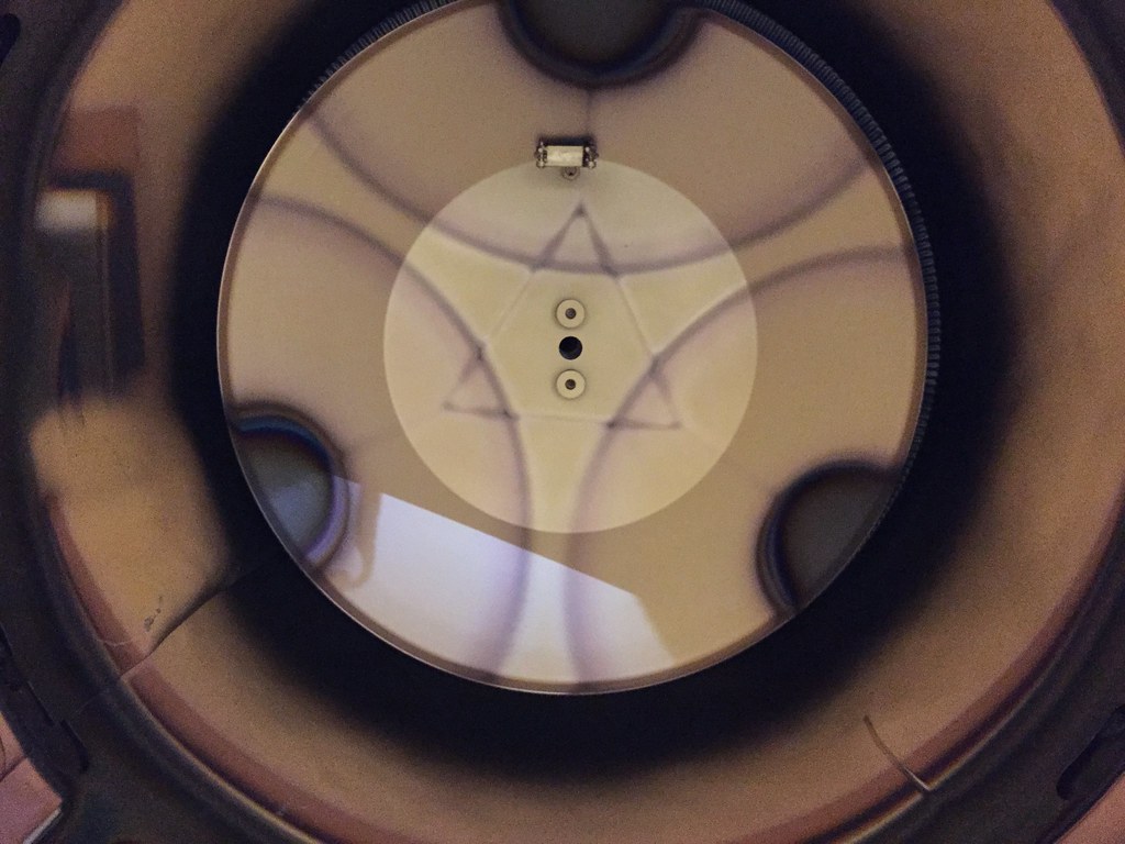
Looking up in the bell jar. The little hole in the center is where the crystal thickness monitor is.
![]()
These are the evaporator boats. Aluminum on the left, copper in the center, and gold on the right.
![]()
-
Filament controller pass bank
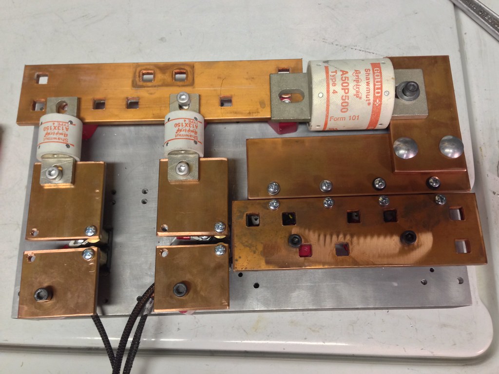
07/20/2014 at 02:32 • 0 commentsI have mostly finished the pass bank for the filament controller. It is separated into three banks, two 100A channels and one 400A channel. The two smaller channels got away with 1 big mosfet each, the 400A channel us using 4 APT20M11JLL mosfets in parallel. I am hoping the will be happy together. They have a very low on resistance (.011 ohm) so they ought to share current nicely.
Drilling holes in the heat sink:
![]()
Mosfets and standoffs in place:
![]()
Copper bus bars and fuses in place:
![]()
-
Turbo running and filament controller
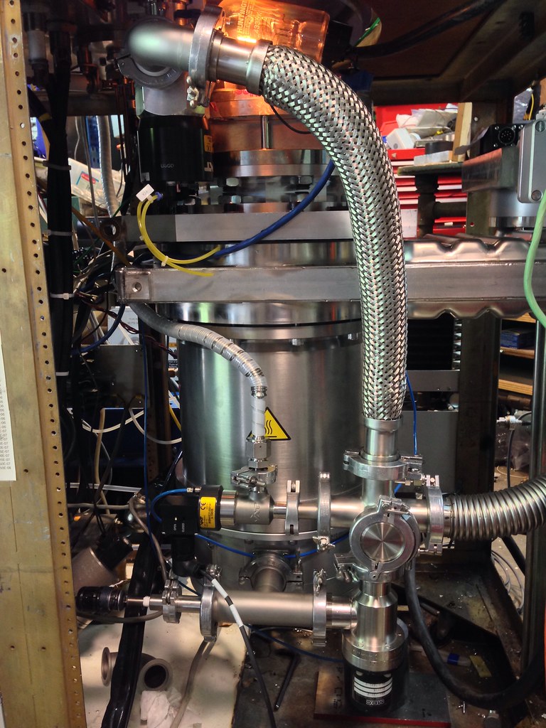
05/27/2014 at 05:56 • 0 commentsGot the pump installed, plumbed in, and running yesterday. It has been running about 30 hours now and is at about 8e-7 torr right now. I thought I had a leak but I cant find a thing with the RGA in leak check mode and a bottle of helium. I think it must be all the water in the system from everything being up to air for so long, especially since I had to rinse the valve body out with hose to get all the crud I scrubbed off out of the system. Well see where it is before I leave for work tomorrow.
I still need to tie the pump into the frame and hook up a couple more pneumatic lines for the roughing valve on the chamber. I used a dual stage valve that allows you to softly pull down the chamber without disturbing things in the chamber.
![Turbo pump installed and running]()
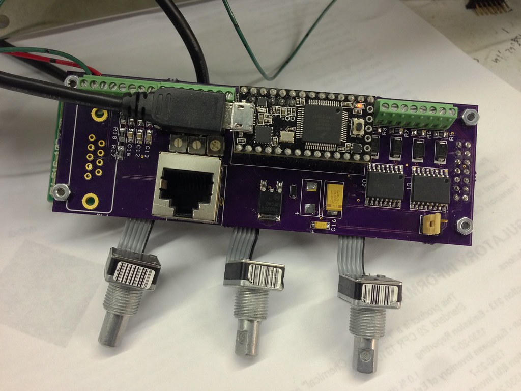
Here are some pics of the filament controller I have been building, it is based on a Teensy 3.0 and the board piggybacks on the back of a Noritake 2x24 VFD. I have used these in several other projects and they are very easy to use, they use the standard HD44870 LCD interface. The module will drive 6 power mosfets forming three controlled channels, two will be limited to about 100 amps, the third will be limited to 400 amps. The mosfets are driven by IR2110 mosfet drivers with a 40khz base frequency at 12vdc gate voltage. The controller gets current feedback from LEM hall effect sensors and voltage feedback through a set of voltage dividers. The controller can be remotely controlled through three 0-10v external voltage sources. Interface is through three 32PPR grayhill encoders. I also installed a RS232 port for external interface if I get that far in the future.
The board also serves to interface the full range Pfeiffer vacuum gauge on the RGA. It reads the 0-8.6v logarithmic voltage signal from the sensor, does the math, and displays the result on the vfd as well as displaying any errors with the sensor.
I need to build the power section next. It will be all bolted down to a heatsink with 150 amp semiconductor fuses on the smaller mosfets and a 500 amp fuse on the 400 amp channel.
![Filament controller boards]()
![Filament controller boards]()
-
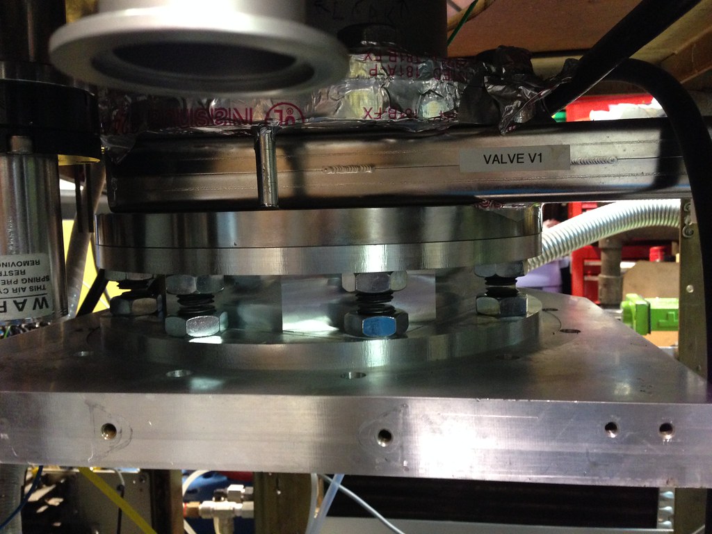
Gate valve cleaning and installation
05/25/2014 at 06:31 • 0 commentsI installed the valve today, it was a total mess on the inside. There was a layer of rust coating the inside of the valve body which just should not happen. The entire thing is made from stainless. It must have been from whatever was being pumped in the system. I disassembled everything and scrubbed it down with scotchbrite and it cleaned up pretty well. I do need to get a new bearings for the gate, they are in pretty sad shape.
I borrowed a hydraulic motorcycle jack to lift the valve in place. Worked rather well. I did have to turn the other gate valve 90 degrees to clear the big valve's mechanism.
Tomorrow I need to run down and pick up some longer bolts. The one I have were just barely long enough to reach. I also need to tie the valve into the frame of the system, there is going to be significantly more weight hanging off there than what was there in the past.
![Vat gate valve]()
-
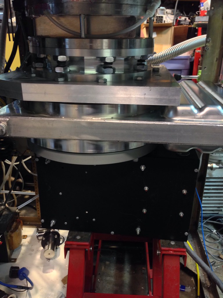
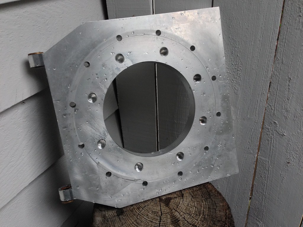
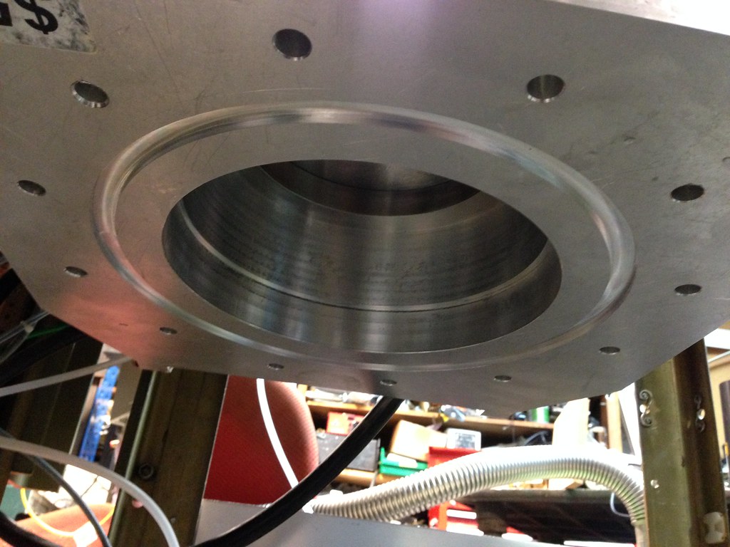
More adapter progress
05/23/2014 at 07:06 • 0 commentsI got a piece of aluminum from a friend for the next part of the adapter, this was an lid from an old plasma etcher. Its a piece aluminum about 14x14 and 1.25" thick. Pretty perfect.
![6" ASA to ISO250 pump adapter]()
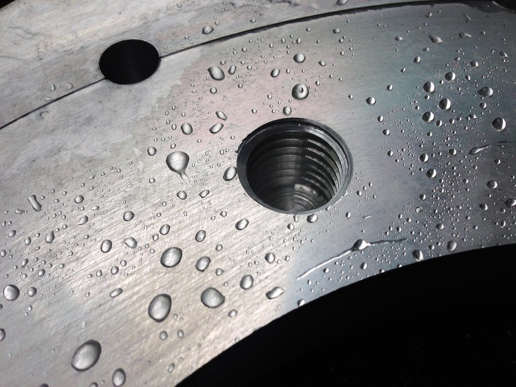
I decided to leave it square, no reason to make it circular in the greater scheme of things. Milled out the chunk in the center leaving the core for the base for the telescope. Spotted and drilled all the holes, 7/16" on the small ones and 5/8" on the large ones. Had a little fun with the 7/16" ones, had a bit explode on my when I lost coolant. Oops.
The 5/8" holes were cleaned up with a mill and then thread milled to 3/4"-10. This was my first attempt at thread milling, one goof and a $80 bit is toast. But it all worked out and had nice, straight threads in a blind hole all the way to the bottom.
![6" ASA to ISO250 pump adapter]()
![6" ASA to ISO250 pump adapter]()
![6" ASA to ISO250 pump adapter]()
After that I cut a groove for the centering ring/seal for the ISO side. I had ordered some new o-rings, 3/4" threaded rod, and half nuts from mcmaster which arrived today. I cut up the rod on the lathe and bolted it all together. Here's hoping it does not leak!
![6" ASA to ISO250 pump adapter]()
Next up is to clean up the gate valve that is going to hang off this adapter and then hand it. Both the gate valve and the turbo are 150lbs each so I need to figure out a way to get them up in place. I am thinking a hydraulic motorcycle lift.
Vacuum System for Deposition
I have been putting a system together for the past few years to do different kinds of deposition.