Close
0%
0%

A 4$, 4ICs, Z80 homemade computer on breadboard

No iron, no cry! Build a mini 4MHz Z80 64kB RAM system with Basic and Forth interpreters, CP/M 2.2, QP/M 2.71, Assembler and C toolchains

Similar projects worth following
This is the Z80-MBC (Mobile Breadboard Computer), a mini 4MHz Z80 64kB RAM system with Basic and Forth interpreters, CP/M 2.2, QP/M 2.71, Assembler and C toolchains.

It is a complete development "ecosystem", and using the iLoad boot mode it is possible cross-compile, load and execute on the target an Assembler or C program with a single command (like in the Arduino IDE).

More, it can be easily expanded and it has an "Arduino heart" using an Atmega32A as an "universal" I/O emulator, and can be used and powered with a tablet or smartphone too...

This project has grown a lot on the way (more than I've supposed at the beginning...) and now is renamed as "Multi Boot Computer" and is available on PCB (thanks to Bill Westfield) too.

* * NOTE * * : The new Z80-MBC2 is out!. Check it here: ( https://hackaday.io/project/159973 )

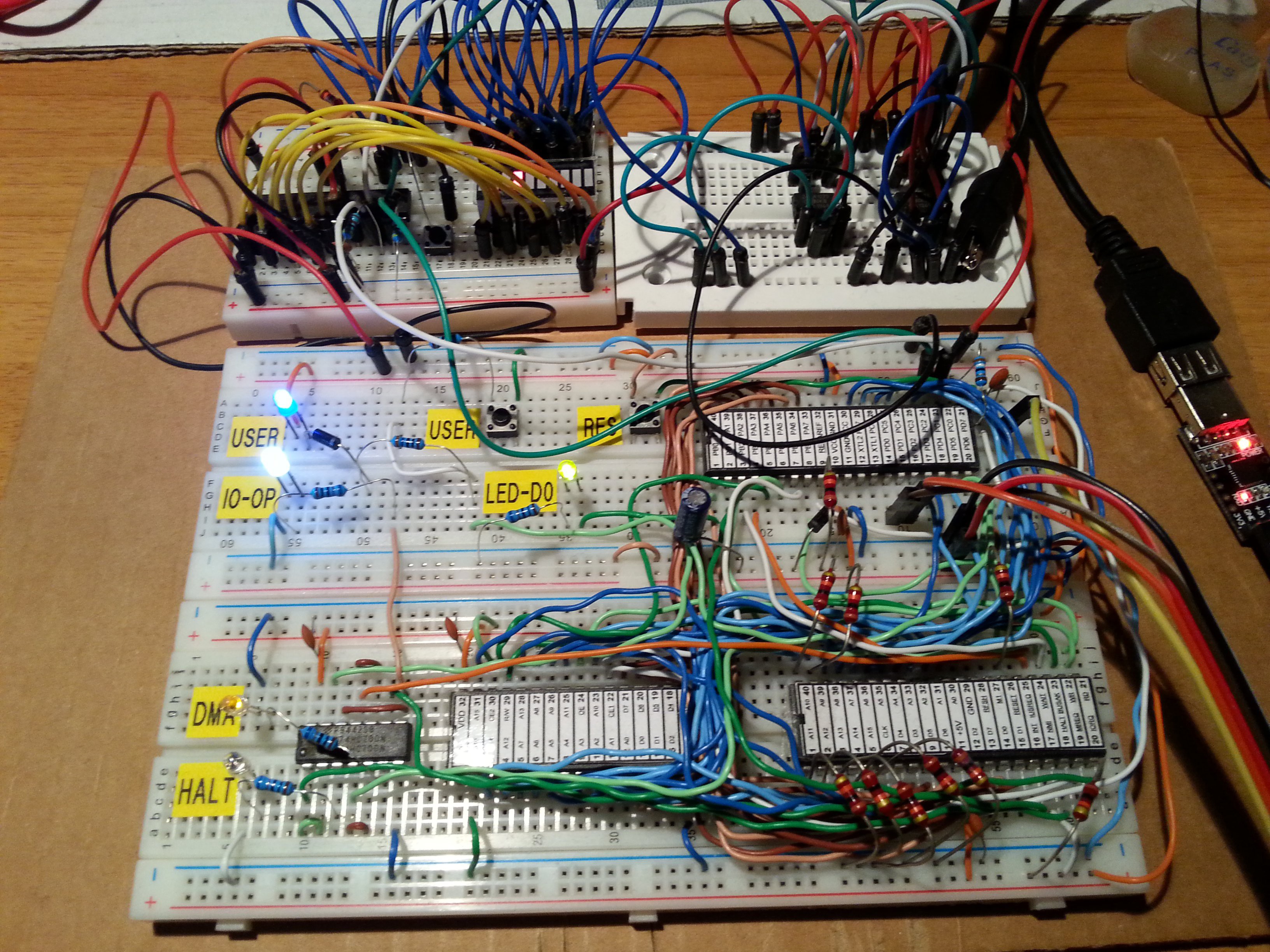
During some surfing on Ebay I realized that with 4$ it is possible to buy enough ICs to build a complete Z80 system that can be done using a breadboard, and taste some flavor of retro computing.... So I did it and here it is the story!

Here is a video with the Z80-MBC in action:

and here with a smartphone (so it is explained the word "Mobile" in his name...) with a common OTG cable (the various test clips in this video were used for some measurements with a Logic Analyzer):


* * HARDWARE OVERVIEW * *


The needed ICs are:

  • Z80 CPU CMOS (Z84C00) 4Mhz or greater ($1.16)
  • Atmega32A ($1.70)
  • TC551001-70 (128kB RAM) ($1.10)
  • 74HC00 ($0.25)

Total cost: $4.21

The wires were taken from salvaged broken LAN cables, and the other components were salvaged from others unused breadboards.

The schematic is attached in the Files section. The MCU Atmega32A is used as universal I/O subsystem, as Eeprom, and as reset and 4MHz clock generator for the Z80 CPU.
Into the Atmega32A it is flashed an Arduino bootloader taken from here , and it is possible to use the Board Manager of the Arduino IDE for that.

Flash the Arduino bootloader at first (with the method you prefer), next you can start to build the whole thing!


Of course I used the Arduino IDE to develop the IOS (I/O Subsytem) that interacts with the Z80 bus and "virtualizes" the peripherals seen by the Z80 CPU.
As oscillator it is used the internal 8MHz Atmega32A oscillator, so no quartz is needed, and from this one is derived the 4MHz clock for the Z80 CPU (so the "Internal 8MHZ osc." bootloader variant must be chosen when flashing the bootloader from the Arduino IDE!).


The 74HC00 is mainly used as RS flipflop to stop the Z80 CPU during I/O operation, giving the needed time to the Atmega32A to interact with the Z80 bus.
The 128kB RAM TC551001 is used only for half (64kB) because the Z80 address space is only 64kB (I've chosen this IC for the low cost).
Note that only the CMOS version of the Z80 CPU can be used here. This because only CMOS version, under given condition that are respected in this schematic, has logical levels compatibles with Atmega32A and 74HC00.


NOTES ABOUT THE COMPONENTS:


You can use any Z80 CMOS speed grade, because the lowest is 4MHz.
The 74HC00 can be substituted with a 74HCT00 if you already have one.
The RAM chip TC551001-70 can be substituted with any suitable 64kB RAM (do not use < 64kB RAM).
The USER led (D5 in the schematic) MUST be blue or white just to be sure that V(forward) is >= 3V.


Here is a video that shows a simple basic program that interacts with the "USER led" and "USER key":


On the breadboard there are others status led: the HALT led turns on if an HALT instruction is been executed and the Z80 CPU is in a Halt state, the DMA led turns on during DMA operations when the Z80 bus is in Hi-Z, the IO_OP led turns on when the Z80 CPU is accessing a I/O virtual device "emulated" by the Atmega32A (as the serial port), the LED_D0 led is the classical "Arduino" led (that one connected to D13 pin on the Arduino Uno) that here is connected with the Arduino D0 pin and is turned on normally as a power on indicator.


The serial port SERIAL-USB (see schematic)...

Read more »

S221116_R050720_Z80.ino

Adds support for 4 drives and others updates. Please see the following repo (created by Al Williams) for new tools, updates and info: https://github.com/wd5gnr/Z80-MBC (by Al Williams)

ino - 165.09 kB - 07/07/2020 at 13:13

Download

S111216.c

TASM Assembler utility.

C Source File - 1.21 kB - 05/15/2018 at 06:05

Download

build.sh

Linux shell script to invoke TASM for WINDOWS (using wine) to assemble Z80 source code and produce a HEX file and a 'C' header file containing the code. Requires TASM 3.2 and wine. See the notes in the script (by Scott).

x-shellscript - 1020.00 bytes - 05/14/2018 at 19:31

Download

optiboot_m32-20mhz.hex

Anyone wishing to overclock the AVR at 20MHz; OptiBoot HEX file for ATmega32/A running at 20MHz (by Scott).

x-hex - 1.31 kB - 05/14/2018 at 18:29

Download

optiboot_m32-8mhz.hex

OptiBoot HEX file for ATmega32/A running at 8MHz (by Scott).

x-hex - 1.31 kB - 05/14/2018 at 18:28

Download

View all 39 files

  • 1 × For the breadboard version see the file "Z80-MBC - BOM.xls" in the Files section
  • 2 × For the PCB version see the file "Z80-MBC PCB version - BOM.xls" in the Files section

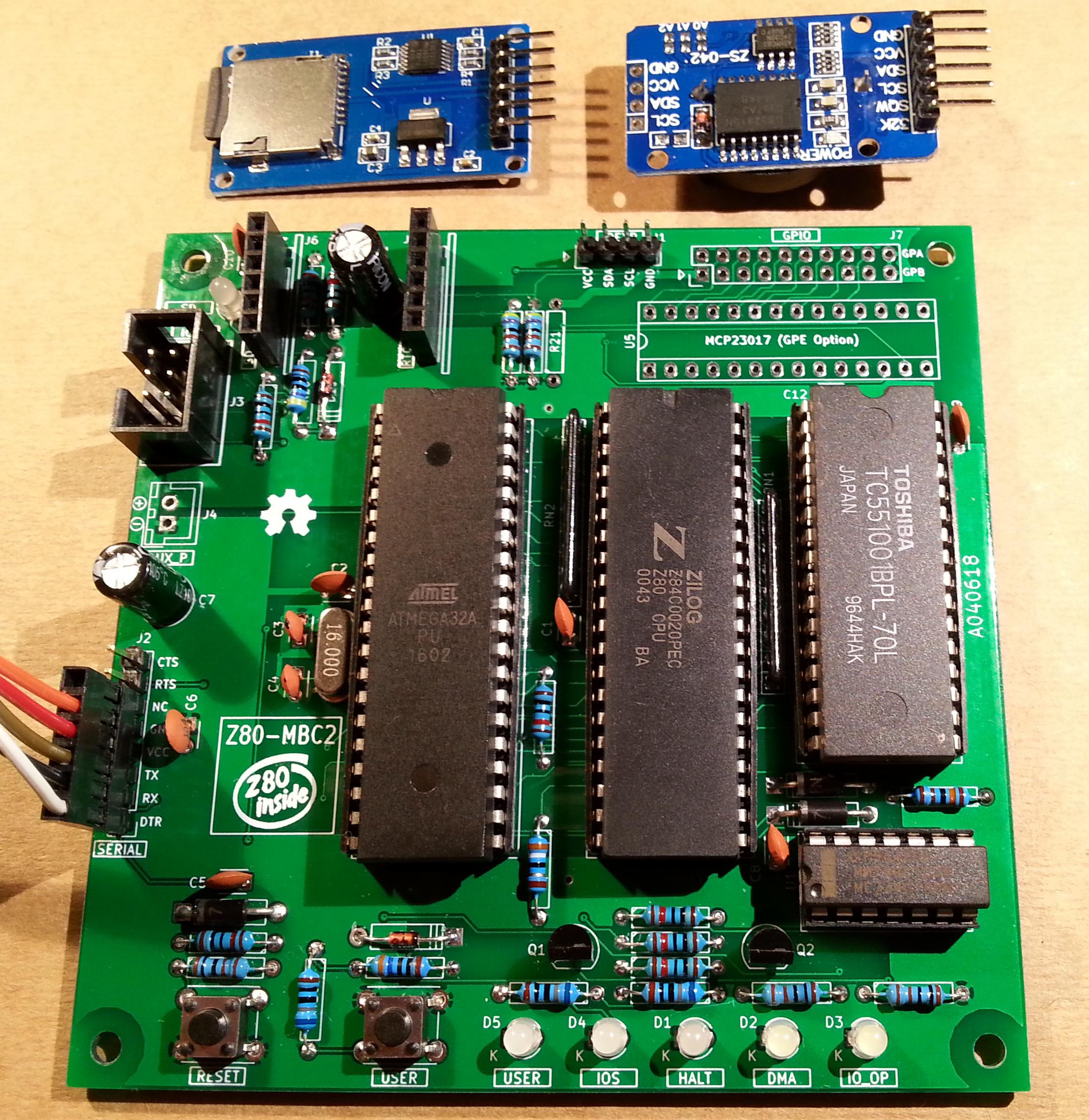
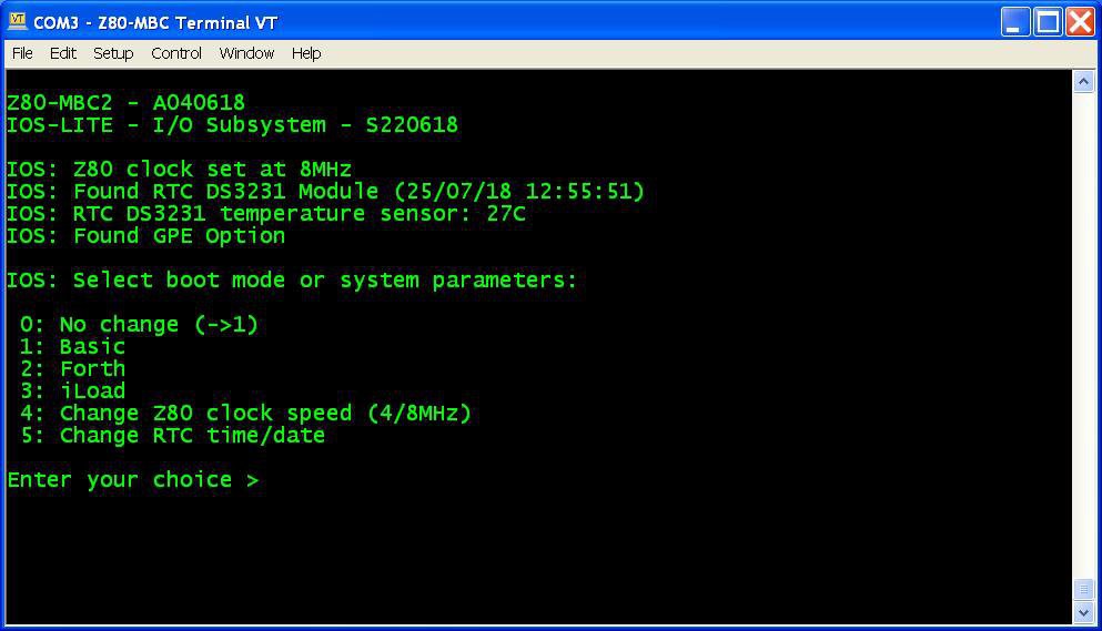
  • The Z80-MBC2 is out!

    Just4Fun07/25/2018 at 16:25 0 comments
  • Hardware Fix for the A041116 schematic (USER led and key)

    Just4Fun07/19/2018 at 18:09 0 comments

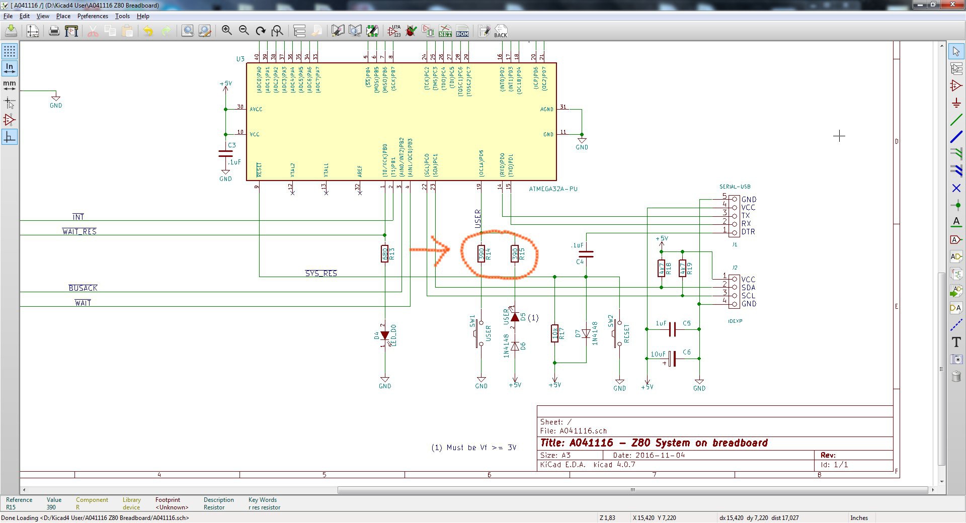
    During some tests on the new Z80-MBC2 I realized that the circuitry of the USER led and key (that is the same used in the Z80-MBC) could cause in some cases an erratic behavior of the USER key (USER key not recognized when pressed).

    The solution is easy, and the fix requires only to change the values of R14 and R15 (see the A041116 schematic) to 390 Ohm (both) as shown:

    Remember that the USER led (D5) must have a forward voltage drop (Vf) of at least 2.7V (e.g. a blue led).

    Please note that this fix is suggested only if you are building a new board or if you are experiencing difficulties with the USER key.

    If you already have a perfect working board there is absolutely no need to apply this fix.

  • Bug fix: the "ghost RTC"

    Just4Fun02/10/2018 at 17:01 0 comments

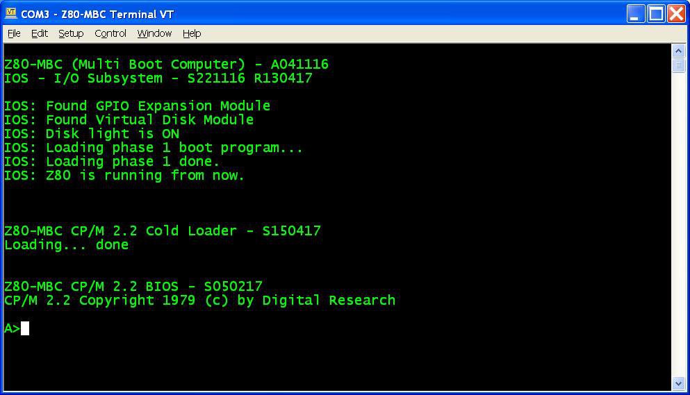
    Reading this Japanese article on a kit sold in Japan to build a Z80-MCB, I realized the presence of a possible bug seeing this two images:

    As you can see, there is a Z80-MCB without any Virtual Disk or RTC attached and in the resulting screenshot the RTC appears present.

    After a quick check I found a little bug in the RTC discovery routine that see a "ghost RTC" when the Virtual Disk is not present.

    So I've uploaded a new "sketch" (S221116_R100218_Z80.ino) that fix the bug.

    Note that if you have the Virtual Disk already installed, there isn't any real need to upgrade.

  • How to make custom Virtual Disk images

    Just4Fun05/29/2017 at 14:29 1 comment

    To do that you need two really powerful tools: Cpmtools to create CP/M disk images and SRecord to manipulate ROM/EPROM images.
    Take in account that the structures of the virtual disk 0 and 1 of the Z80-MBC are different. Disk 0 has the two first tracks reserved for the system image (loaded into RAM by the CP/M loader), instead disk 1 doesn't have this "reservation". This means that the images have a different "structure". More, because disk 0 must have the system image inside the two first tracks, the disk 0 image creation will be different if the OS is CP/M rather than QP/M.
    So to make things easier I've prepared some batch file to simplify the needed operations.
    As for the Assembler and C toolchains you need a Windows host or VM.


    Here all the steps to set up the needed tools:

    1. Create a working directory on your Windows Machine;
    2. Download Cpmtools and unzip in your working directory;
    3. Download last version of SRecord and unzip in your working directory;
    4. Download from the Files section CPMtools-custom.zip and unzip the files into the directory containing the Cpmtool executables (as cpmcp.exe). During the copy overwrite the file DISKDEFS because the new one contains the needed definitions for the Z80-MBC;
    5. Download from the Files section SRecord-custom.zip and unzip the files into the directory containing the SRecord executables (as srec_cat.exe).

    Now you are ready to create your custom image. First create a sub-directory (called e.g. CPM-files) in the cpmtools directory to store all the files to load in the disk image. Check that they fit into the 128kB avaliable space.


    Steps to create a Disk 1 image

    1. Go to the cpmtools directory and with an editor modify/add/delete in the file MakeDisk1.bat the various lines "cpmcp -f z80mbc-d1 %dskfile% CPM-files\xxxxx.yyy 0:xxxxx.yyy" to match the directory in your host (if needed) and all the files to load (xxxxx.yyy);
    2. From the cpmtools directory open the provided DOS command shell and give the following command (I'll use here the name disk1.dsk for the disk image file):
      MAKEDISK1 disk1.dsk
    3. After the execution copy the file disk1.dsk in the SRecord directory;
    4. Go to the SRecord directory, open the provided DOS command shell and give the following command:
      D1TOHEX disk1.dsk
    5. After the execution you will find four files named from disk1_SEG0.hex to disk1_SEG4.hex to upload into the virtual disk with iDisk.


    Steps to create a Disk 0 CP/M image

    1. Go to the cpmtools directory and with an editor modify/add/delete in the file MakeDisk0CPM.bat the various lines "cpmcp -f z80mbc-d0 %dskfile% CPM-files\xxxxx.yyy 0:xxxxx.yyy" to match the directory in your host (if needed) and all the files to load (xxxxx.yyy);
    2. From the cpmtools directory open the provided DOS command shell and give the following command (I'll use here the name disk0CPM.dsk for the disk image file):
      MAKEDISK0CPM disk0CPM.dsk
    3. After the execution copy the file disk0CPM.dsk in the SRecord directory;
    4. Go to the SRecord directory, open the provided DOS command shell and give the following command:
      D0TOHEXCPM disk0CPM.dsk
    5. After the execution you will find four files named from disk0CPM_SEG0.hex to disk0CPM_SEG4.hex to upload into the virtual disk with iDisk.


    Steps to create a Disk 0 QP/M image

    1. Go to the cpmtools directory and with an editor modify/add/delete in the file MakeDisk0QPM.bat the various lines "cpmcp -f z80mbc-d0 %dskfile% CPM-files\xxxxx.yyy 0:xxxxx.yyy" to match the directory in your host (if needed) and all the files to load (xxxxx.yyy);
    2. From the cpmtools directory open the provided DOS command shell and give the following command (I'll use here the name disk0QPM.dsk for the disk image file):
      MAKEDISK0QPM disk0QPM.dsk
    3. After the execution copy the file disk0QPM.dsk in the SRecord directory;
    4. Go to the SRecord directory, open the provided DOS command shell and give the following command:
      D0TOHEXQPM disk0QPM.dsk
    5. After the execution you will find four files named from disk0QPM_SEG0.hex to disk0QPM_SEG4.hex to upload into the virtual disk with iDisk.

    Remember that you...

    Read more »

  • A new OS: QP/M 2.71 and a RTC for timestamping

    Just4Fun05/23/2017 at 15:37 0 comments

    Here is an interesting alternative to CP/M developed by MICROCode Consulting that supports also file timestamping, and it is 100% CP/M 2.2 "compatible".
    MICROCode Consulting has released the original installation files and all the documentation in their site with the "restricted usage" condition, that means free for non-commercial use and for personal use only, so it should be ok for us. Anyway I've sent them a mail about this project.
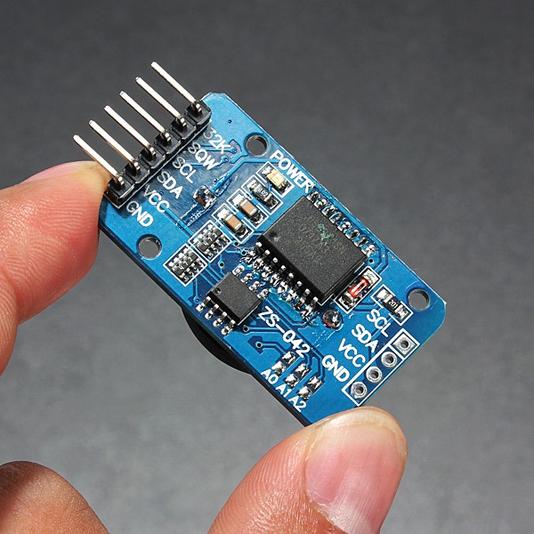
    To enable timestamping you need a DS3231 based RTC module like this one:

    WARNING: these modules can cause battery "explosion"! How to fix it

    This cheap modules have a trickle charging circuit that may cause the "explosion" of the battery if you use a standard CR2032 cell. More, it can damage also a rechargeable LIR2032 cell (see this thread). So the safer thing is "disable" the trickle charging circuit (a CR2032 can last 5/10 years, so there is no practical need to a rechargeable battery, after all...).
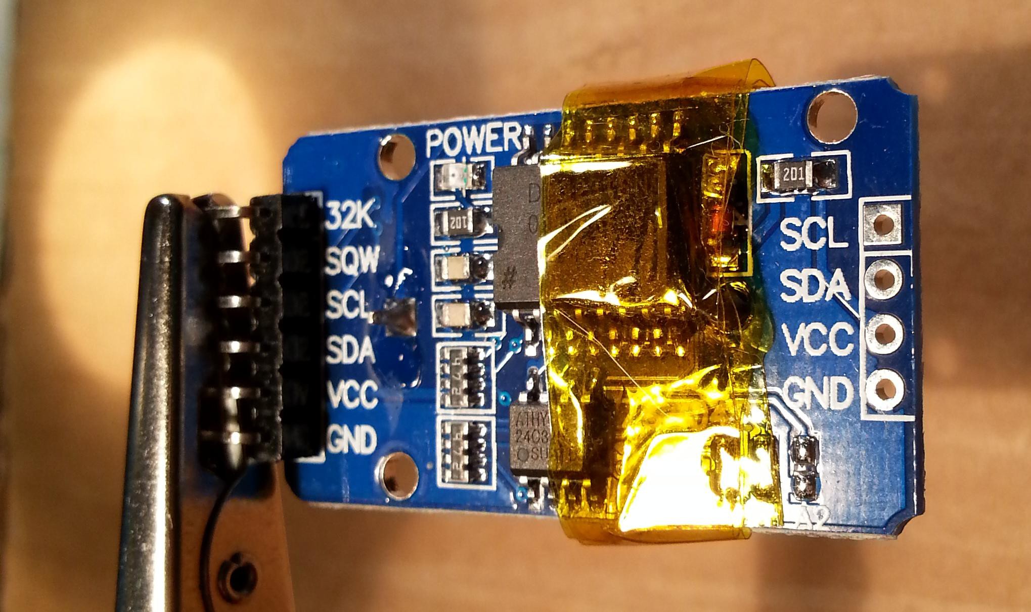
    To avoid any charging current flowing into the battery you can take away the series limiting 200 Ohm resistor (or cut the trace). Alternatively you can take away the red diode, or destroy it (it is in series with the 200 Ohm resistor). In the following photo you can see the module with some Kapton tape (used as thermal barrier) before to desolder the 200 Ohm resistor (on the right marked as 201) with an hot air gun:

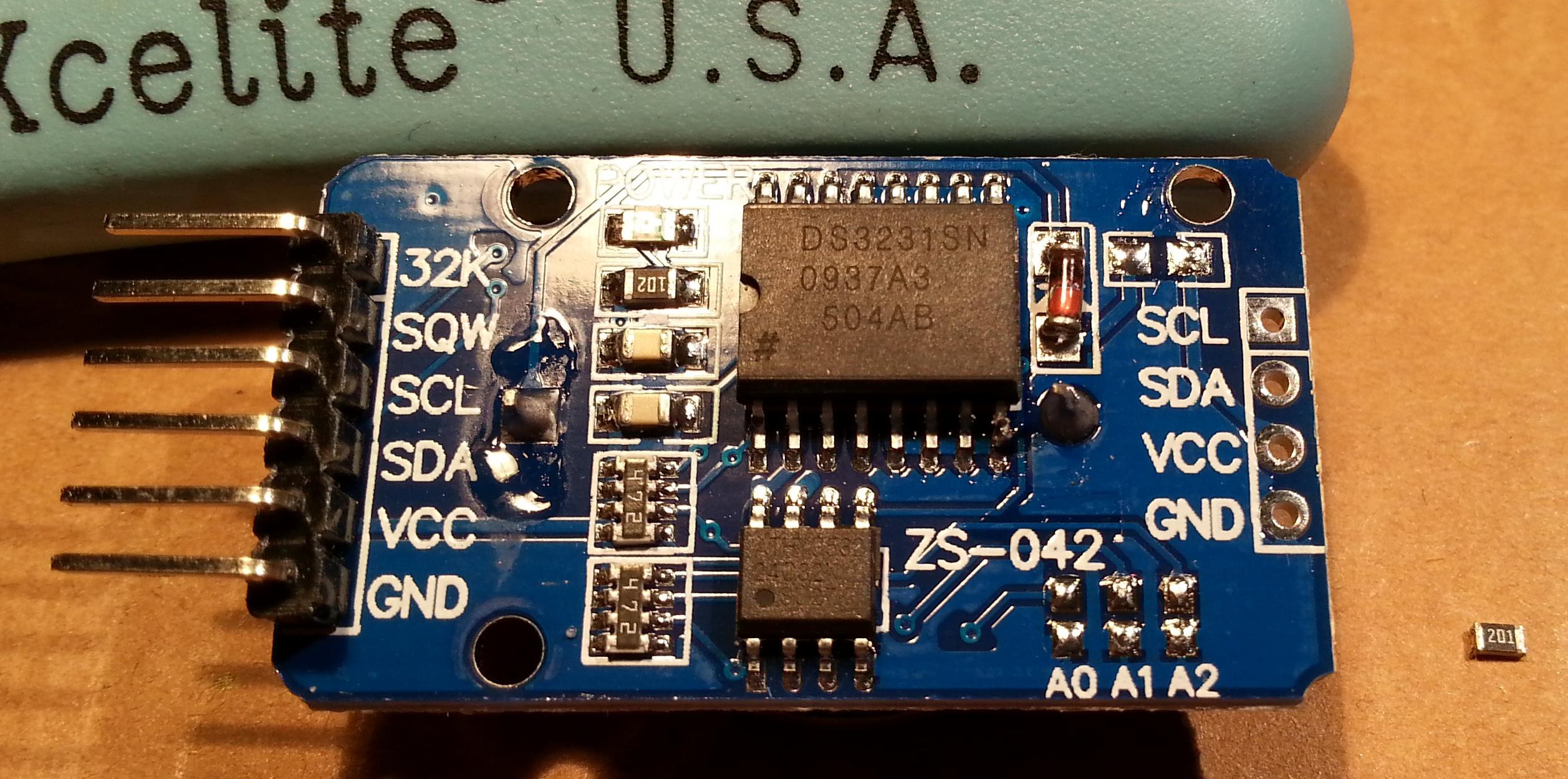
    And here after the desoldering:

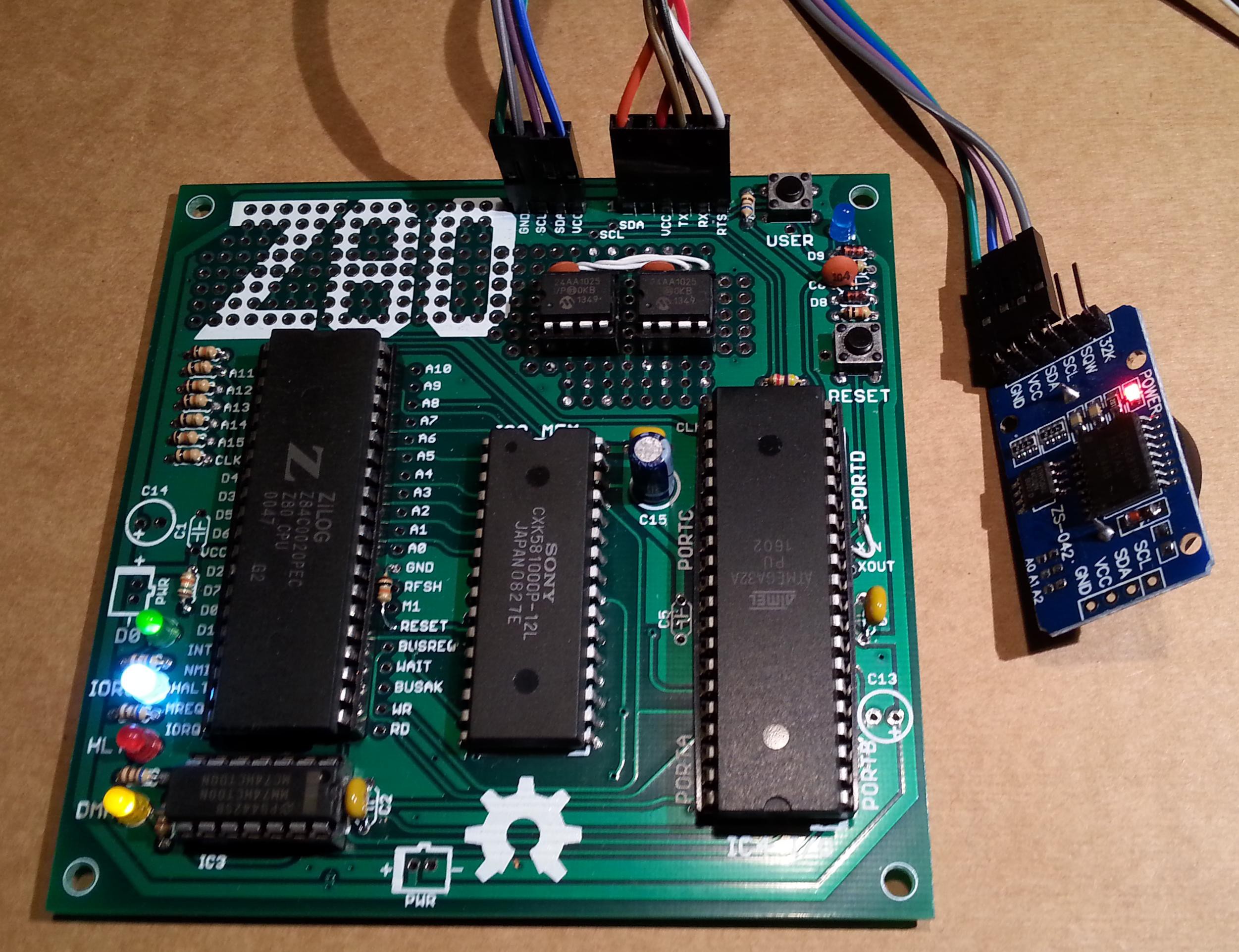
    Now the module it's safe and a CR2032 can be used. To connect it use the SCL/SDA/VCC/GND terminals and connect them at the corresponding pins of the IOEXP/I2C connector of the Z80-MBC (pay attention because the position of the signals is different):

    QP/M quick set up guide

    The setup is quite similar to those used to install CP/M. The Assembler automated toolchain must be already set up and the Virtual Disk Module present.

    Here all the steps:

    1. Connect the DS3231 module (with the CR2032 battery inside);
    2. Update the IOS using the new file S221116_R100218_Z80.ino in the File section;
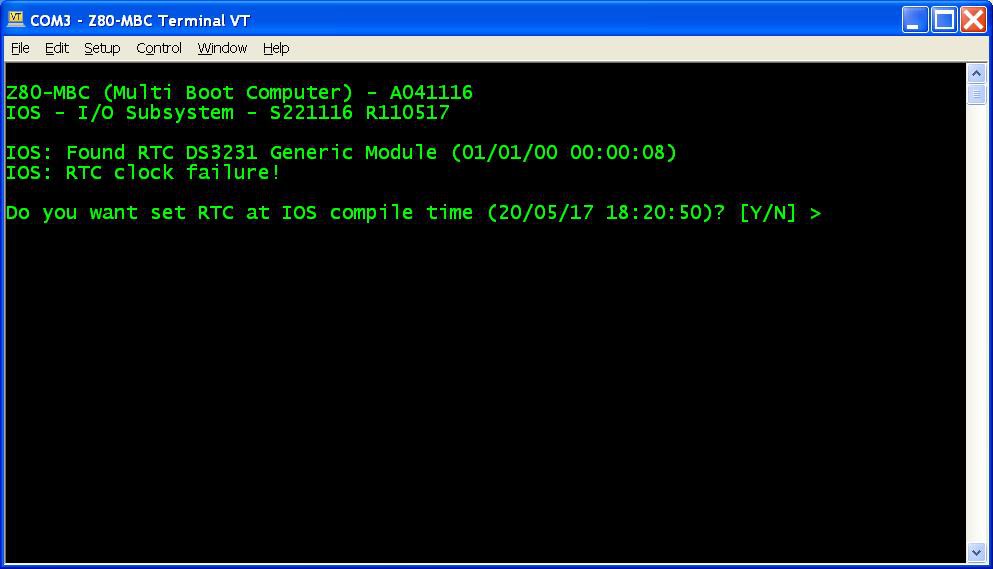
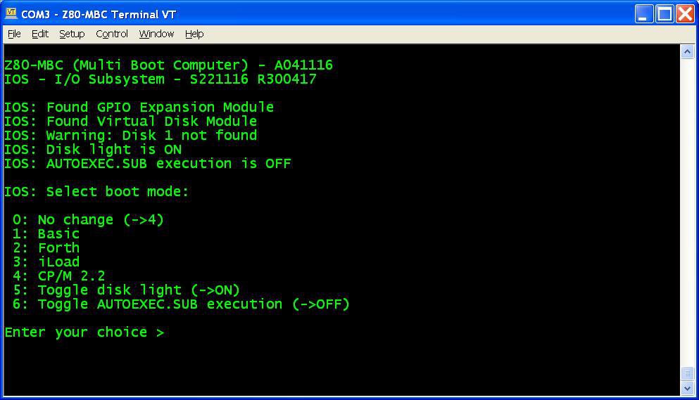
    3. Reboot the Z80-MBC and from a terminal emulator you'll see this:
      Press Y. If you are enough fast you have the RTC set up with the right date/time taken from the sketch compile time (if you are lazy like me you'll find this very handy...). In any case it is possible adjust the date/time manually too from the boot selection menu;
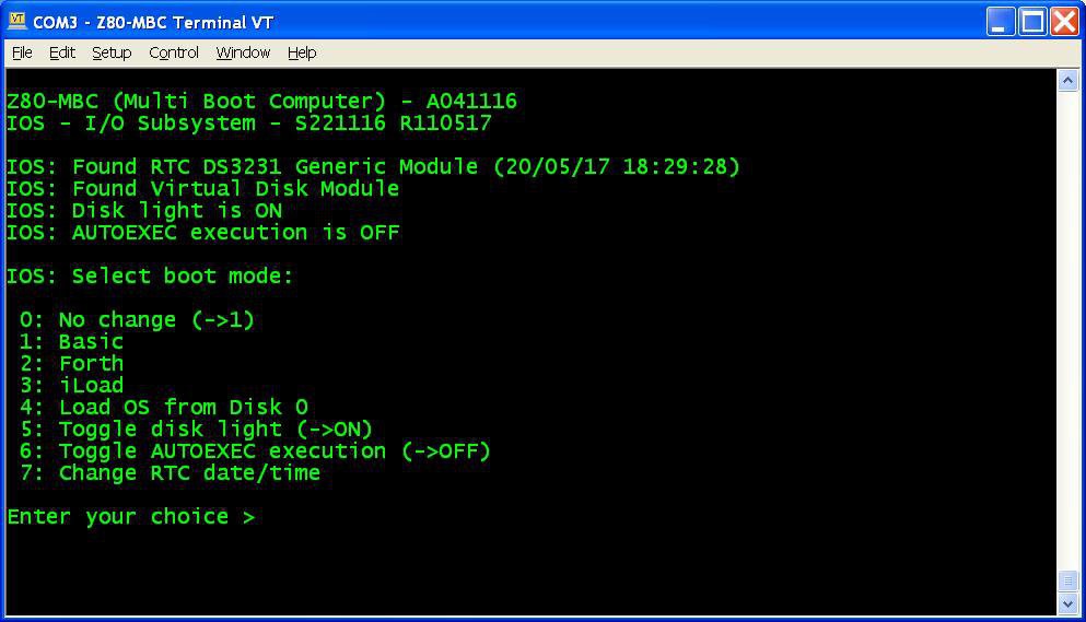
    4. Reboot the Z80-MBC again and select the iLoad boot mode;
    5. From the File section download the file "QPM271_DiskPack.zip", unzip it in the directory used for the Assembler automated toolchain;
    6. Upload the file "iDisk - S250317.hex" to the Z80-MBC using the Dos batch L.BAT (see Assembler automated toolchain) with the command:
      L "iDisk - S250317.hex"
      
    7. When iDisk waits for the input stream, from the Tera Term menu select "File" -> "Send file..." and choice one of the unzipped .hex file from QPM271_DiskPack.zip;
    8. Repeat step 7 for all the four files;
    9. Press the Reset button on the Z80-MBC and enter into the boot selection menu and select 4 to load the OS from disk 0 (and select the disk light ON if not already done, to have an idea of the behavior):

    NOTE: as already noticed, if you experience errors during the serial upload increase the delay after each line from the Tera Term menu (Setup -> Serial port -> Transmit delay -> msec/line). In my VM I set up a 90ms delay. This is due because Arduino serial port doesn't have any handshaking.

    Now you have QP/M 2.71 up and running, but you need further operations to enable the file timestampig (as stated in the QP/M Installation Guide):

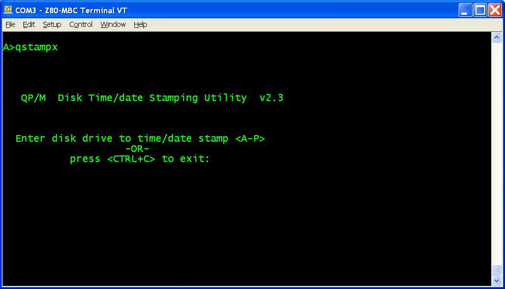
    1. To enable file disk timestamping it is necessary run the utility QSTAMPX from A:
      and do the "disk timestamping" for both A: and B: disks.
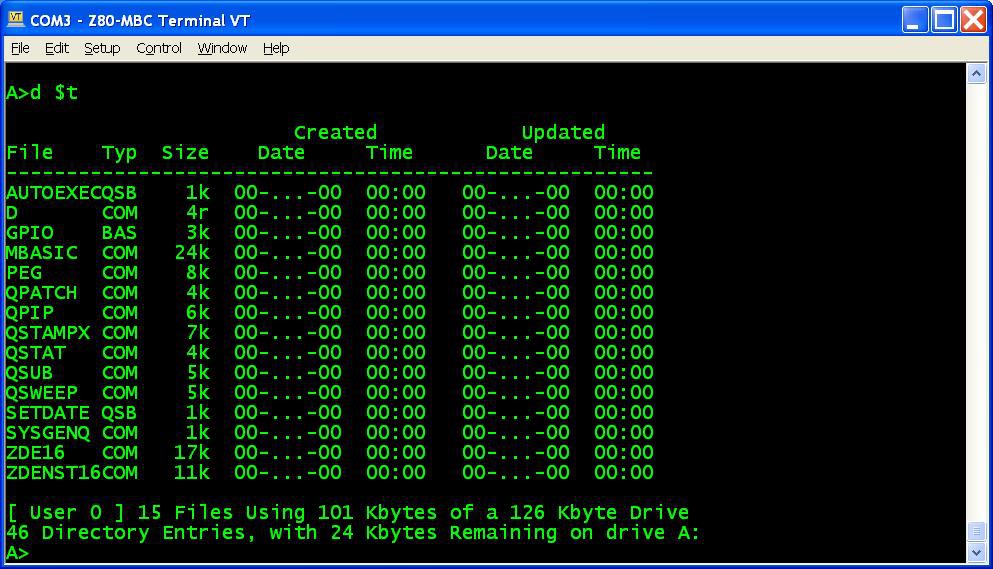
      When done type the command D $T and check that the output is similar to this:
    2. Now to set up a starting date to all files give the command QSUB SETDATE to run a simple batch that I made to do this initialization easily;
    3. Copy the file SETDATE.QSB to drive B: (using the command QPIP B:=SETDATE.QSB) and repeat from B: the same batch (QSUB SETDATE)....
    Read more »

  • AUTOEXEC for CP/M

    Just4Fun05/02/2017 at 16:39 1 comment

    Playing with the Z80-MBC I realized that there was a missing feature: to run a program automatically after the "cold" boot.
    So after some searches I found a way to implement in the BIOS a function similar to AUTOEXEC.BAT for DOS using the CP/M SUBMIT command and a batch file that I called AUTOEXEC.SUB (of course...).
    Editing the AUTOEXEC.SUB file it is possible to run a sequence of commands after the cold boot (as with AUTOEXEC.BAT for DOS), and it is possible enable or disable the execution of the AUTOEXEC batch file from the IOS boot selection menu (but this isn't possible with DOS...).


    AUTOEXEC for CP/M quick set up guide

    You must have CP/M 2.2 already up and running (see CP/M 2.2, iDisk and a new IOS), and you can have also only a "single disk" installed (but I recommend the original dual disk configuration), meaning that only U1 (see the A110417 schematic) is populated. Of course the Assembler automated toolchain must be already set up.


    Here all the steps:

    1. Update the IOS using the new file S221116_R300417_Z80.ino in the File section;
    2. Reboot the Z80-MBC and select the iLoad boot mode;
    3. From the File section download the file CPM22SYS_BIOS_S050217_R300417.hex. This file contains only the new CP/M system image for the system tracks of Disk 0, so the "user files" will be left untouched;
    4. Upload the file "iDisk - S250317.hex" to the Z80-MBC using the Dos batch L.BAT (see CP/M 2.2, iDisk and a new IOS) with the command:
      L "iDisk - S250317.hex"
    5. When iDisk waits for the input stream:from the Tera Term menu select "File" -> "Send file..." and choice CPM22SYS_BIOS_S050217_R300417.hex. After the upload iDisk will show a summary, at this point press W to proceed and confirm your choice (as done for the CP/M 2.2 installation described in CP/M 2.2, iDisk and a new IOS). Wait until the write and verify phase is completed.
    6. Press the Reset button on the Z80-MBC and enter into the boot selection menu and select 4 for CP/M loader.


    All done!


    NOTE: as already noticed, if you experience errors during the serial upload increase the delay after each line from the Tera Term menu (Setup -> Serial port -> Transmit delay -> msec/line). In my VM I set up a 90ms delay. This is due because Arduino serial port doesn't have any handshaking.


    How use it

    To create or edit AUTOEXEC.SUB from drive A, you can use the ED command or an other editor like the Turbo Pascal editor. In this case remember to terminate the file with a CR, or "strange" things will occur when executing the SUBMIT AUTOEXEC command.
    You can test the execution giving the command SUBMIT AUTOEXEC from drive A (you can omit the extension .SUB inside the SUBMIT command).
    To enable the AUTOEXEC execution after the cold boot change the corresponding state to ON from the usual IOS boot selection menu.
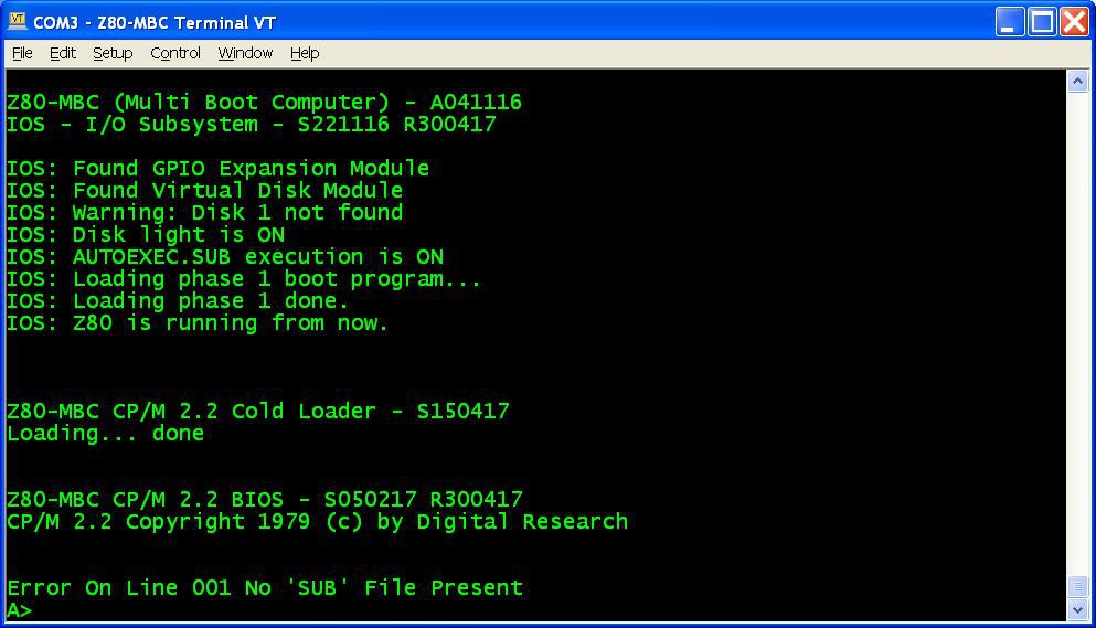
    If the AUTOEXEC is enabled but the AUTOEXEC.SUB file doesn't exist in the drive A, an error will be displayed:


    New "disk packs"

    I've updated both "disk packs" in the files CPM22_DualDiskPack_v2.zip and CPM22_SingleDiskPack_v2.zip with the new BIOS in the system tracks. So if you are installing them for the first time or you need for any reason to reload them, the new BIOS will be installed. I've added an example of AUTOEXEC.SUB too.


    How it works

    The "trick" used was to inject the string "SUBMIT AUTOEXEC" into the CCP (the Command Processor of CP/M) input buffer. The BIOS after the cold boot checks if the AUTOEXEC flag is set in the IOS, and in this case makes the injection. When the CCP starts after the cold boot, it runs this injected command.

    In this video there is an in depth explanation for a "legacy" Altair 8800 clone.

    The CP/M 2.2 and the new BIOS sources are in the file "CPM22 BIOS - S050217 R300417.zip" in the File section.

  • CP/M 2.2, iDisk and a new IOS

    Just4Fun04/20/2017 at 20:36 14 comments

    CP/M 2.2 quick set up guide

    The set up is very simple. I've done an utility (iDisk) to simplify all the needed operations. Of course the Virtual Disk Module must be present, but you can have also only a "single disk" installed (but I recommend the original dual disk configuration), meaning that only U1 (see the A110417.pdf schematic) is populated.
    The Assembler automated toolchain must be already set up.


    Here all the steps:

    1. Update the IOS using the new file S221116_R130417_Z80.ino (or a newer version if present) in the File section;
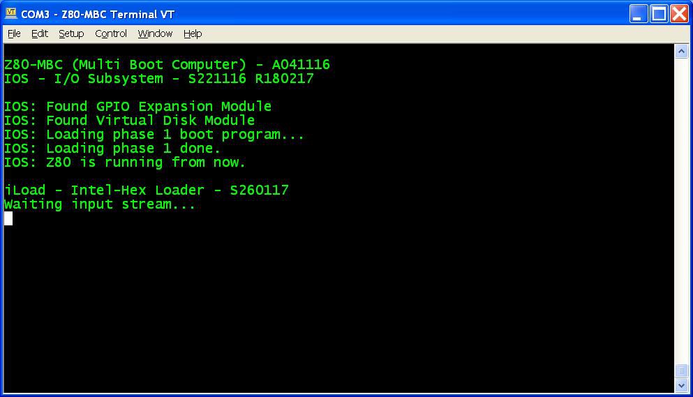
    2. Reboot the Z80-MBC and select the iLoad boot mode (if not already selected);
    3. From the File section download the file "iDisk - S250317.hex" and copy it into your PC in the directory used for the Assembler automated toolchain . (Do not use the source file "iDisk - S250317.c" because it requires a special compiling option);
    4. From the File section download the file "CPM22_DualDiskPack.zip" and unzip it (for a single disk configuration download the file "CPM22_SingleDiskPack.zip"). Each disk image is divided into four .hex files called "segment" (32kB each) that are named accordingly (e.g. D0XXX_SEG1.hex means the segment 1 of disk 0);
    5. Upload the file "iDisk - S250317.hex" to the Z80-MBC using the Dos batch L.BAT (see Assembler automated toolchain) with the command:
      L "iDisk - S250317.hex"
          
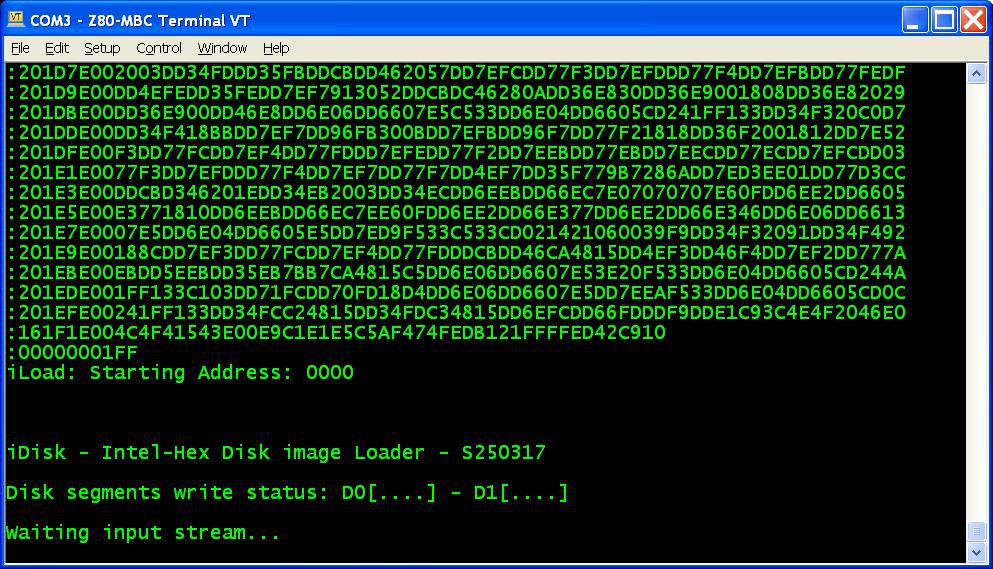
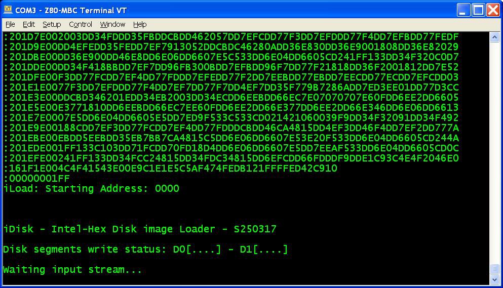
    6. When iDisk waits for the input stream:
      from the Tera Term menu select "File" -> "Send file..." and choice one of the unzipped .hex file from CPM22_DualDiskPack.zip (or CPM22_SingleDiskPack.zip for a single disk configuration). After the upload iDisk will show a summary:
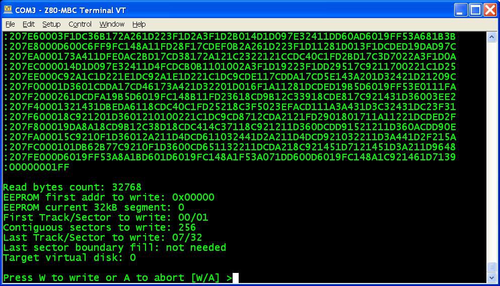
      at this point press W to proceed and confirm your choice.
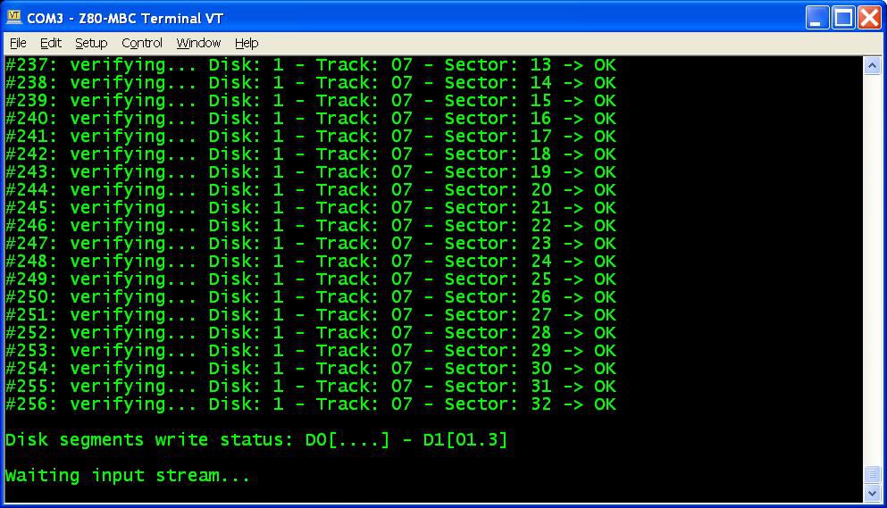
      You don't have to follow any order in the "segments" upload sequence, iDisk will know how to do. To know before each upload what "segments" have been already written into the disks just see the "Disk segment write status":
      in the photo the segments 0, 1 and 3 of Disk 1 have been already successfully written, so you can choose any of the remaining;
    7. Repeat step 6 for all the eight (or four for the single disk pack) "segment" files;
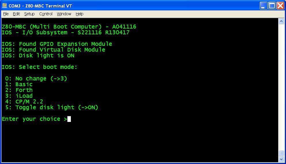
    8. Press the Reset button on the Z80-MBC and enter into the boot selection menu:
      select 4 for the CP/M loader (and select the disk light ON if not already done, to have an idea of the behavior).
    All done!


    NOTE: if you experience errors during the serial upload increase the delay after each line from the Tera Term menu (Setup -> Serial port -> Transmit delay -> msec/line). In my VM I set up a 90ms delay. This is due because Arduino serial port doesn't have any handshaking.

    Disk speed

    The Virtual Disk Module is based on simple EEPROMs using a 200KHz I2C serial bus. Of course do not expect the same speed of an hard disk with a DMA controller!
    The speed probably is like using the floppy drive of those days...

    Single disk configuration

    You can have also only a "single disk" installed (but I recommend the original dual disk configuration), meaning that only U1 (see the A110417.pdf schematic) is populated.

    In this case you have about 120kB free, because the first two tracks of Disk 0 are reserved for the system image (Disk 1 doesn't have the system image, so all the 32 tracks are used for the file system).

    Because the BIOS is the same and is configured for a dual disk system, if you try to select the "B:" drive you'll get a "BAD SECTOR" error.

    Disk pack contents

    In the disk 0 image there are the various external CP/M commands, the Basic interpreter, the CP/M Assembler and the Macro Assembler.
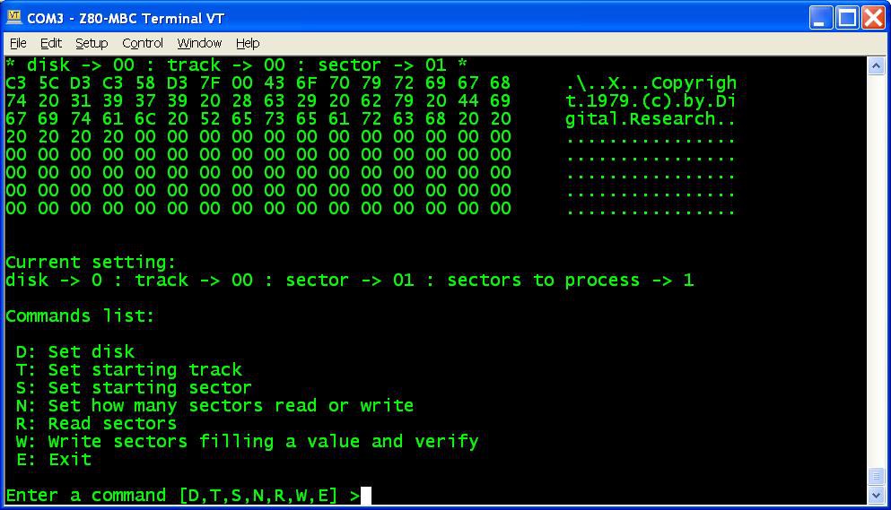
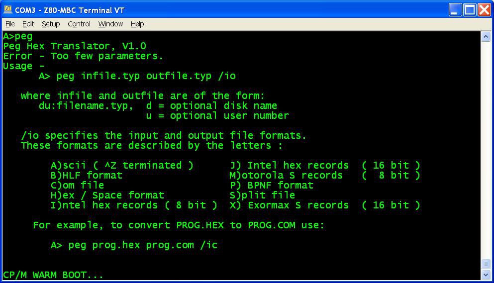
    I've added also D, an alternative DIR command, and PEG, a bin to hex converter (and vice-versa) to exchange files:

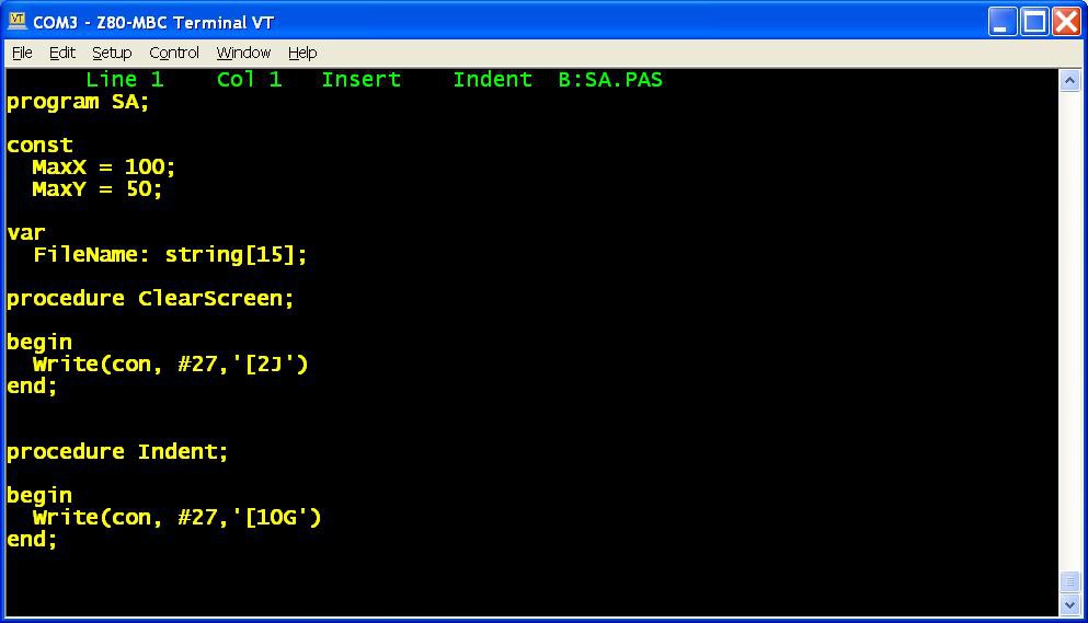
    In the disk 1 image there is the complete Turbo Pascal compiler v3.01A with a sample program (SA.PAS):

    In the "single disk pack" the CP/M Assembler and the Macro Assembler are missing, and the Turbo Pascal is without the installing executable (not a big issue anyway) and without the sample program.
    In a next Log I'll explain how create custom...

    Read more »

  • Virtual Disk Module, a new IOS and ViDiT

    Just4Fun04/13/2017 at 19:37 3 comments

    It's time for a new "module", the Virtual Disk Module! In the photo is that one on the right, near the previous GPIO module.

    In the File section is possible see the simple schematic A110417.pdf with two I2C EEPROM 24LC1025.

    With this module it is possible to emulate two disks of 128kB each (probably like the floppy disk drives of those years).

    Each disk is divided into 32 tracks of 32 sectors. Each sector is 128 bytes long.

    Of course to manage this new HW there is a new release of IOS. The new file S221116_R180217_Z80.ino is in the File section.

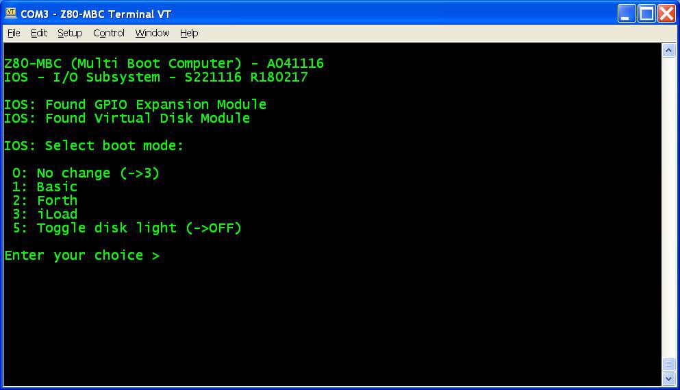
    This new IOS checks if the module is present and prints a message if found:

    There is also a new item in the boot selection menu if the virtual disk is found, to use the User led as a disk activity led:

    I suggest to activate this option to have an idea of the behavior.


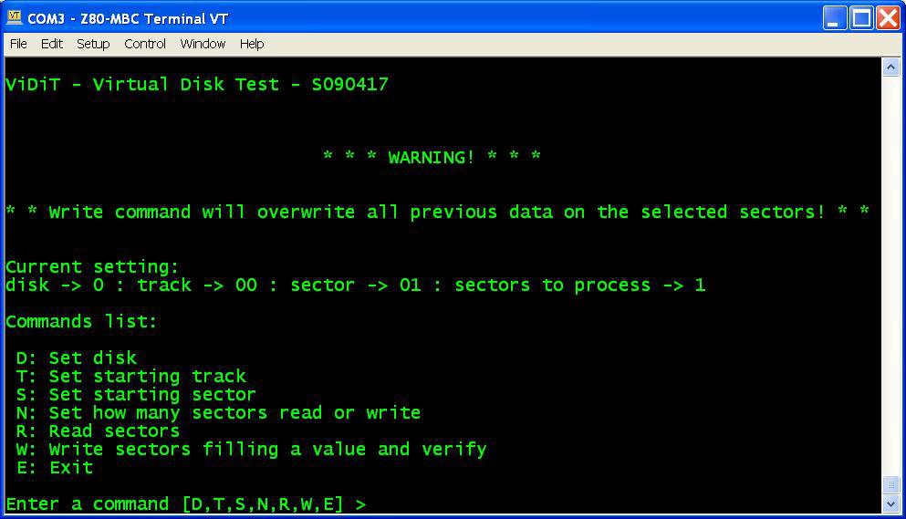
    ViDiT

    In the File section I've added a simple test program (file "ViDiT - S090417.c") to check the virtual disk. Of course you need to compile it with the C "toolchain":


    About I2C speed

    With this IOS the I2C speed is 200KHz. Note that if you are using a 16MHz external quartz to clock the Atmega32 the I2C speed will be 400kHz. In this case I suggest to lower the two 4k7 pull-up resistors (on SDA and SCL signals) to about 2k2.


    The next Log will bring the CP/M 2.2 up and running...

  • Forth language, new multi-boot selection and a new name

    Just4Fun02/17/2017 at 21:33 4 comments

    Forth


    Thanks to Bill Westfield now we have a new language for the Z80-MBC, the fig-FORTH v1.3 (here the link to the Bill GitHub repository with the source he adapted for the TASM assembler with the needed modifications for the Z80-MBC).

    The acronym "fig" stands for "Forth Interest Group", that was a world-wide non-profit organization (now dissolved) for the promotion of the Forth computer language.
    I've just started to play with this thing, and I must say that it is not the most friendly language I've seen... anyway it is an interesting different approach.

    To enable Forth just upload the new IOS release S221116_R120217_Z80.ino in the Files section, and select the Forth language from the new multi-boot menu (see next paragraph).

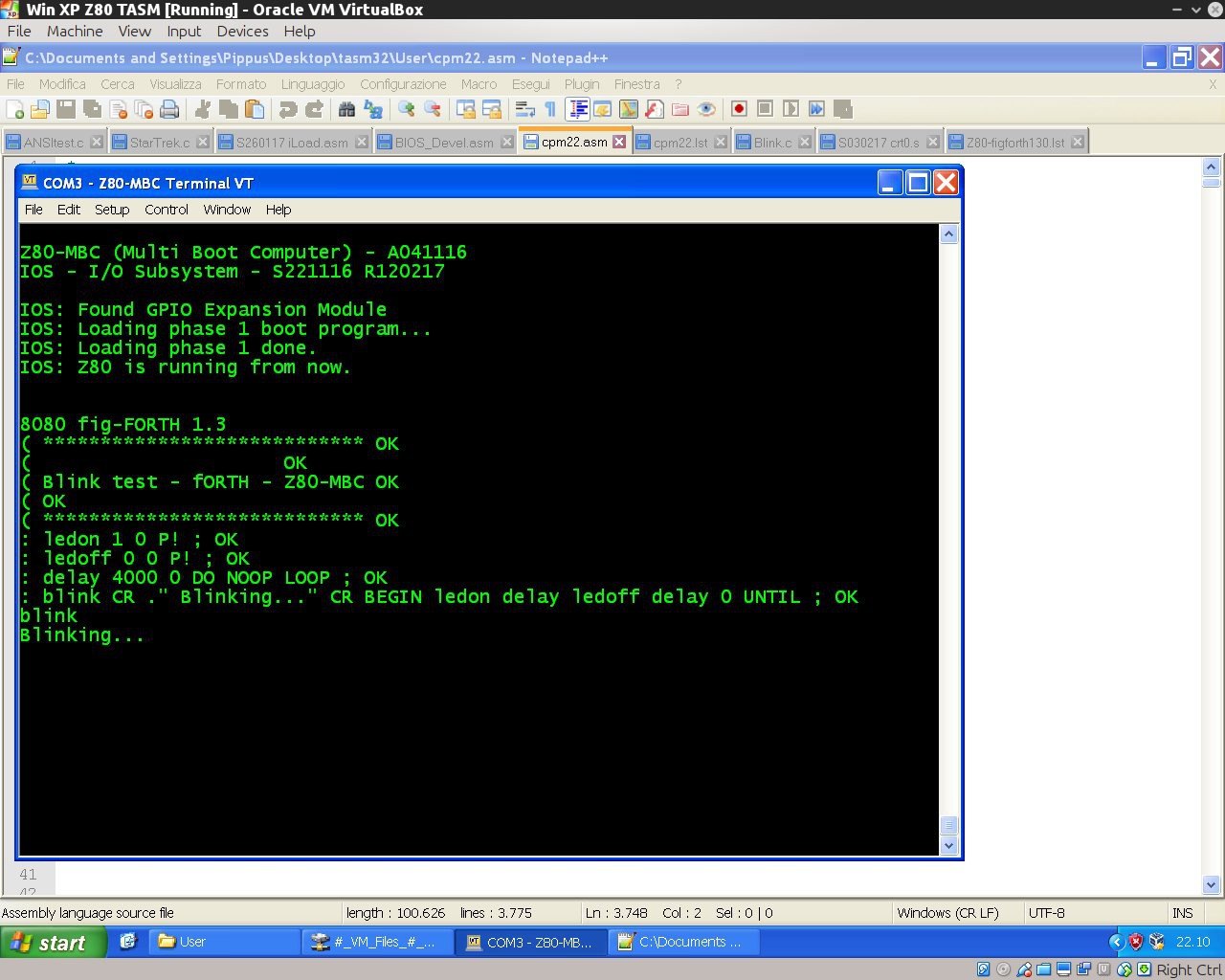
    Here it is a "blink" demo program:

    ( ****************************
    (                     
    ( Blink test - Forth - Z80-MBC
    (
    ( ****************************
    : ledon 1 0 P! ;
    : ledoff 0 0 P! ;
    : delay 4000 0 DO NOOP LOOP ;
    : blink CR ." Blinking..." CR BEGIN ledon delay ledoff delay 0 UNTIL ;

    To execute give the command "blink":


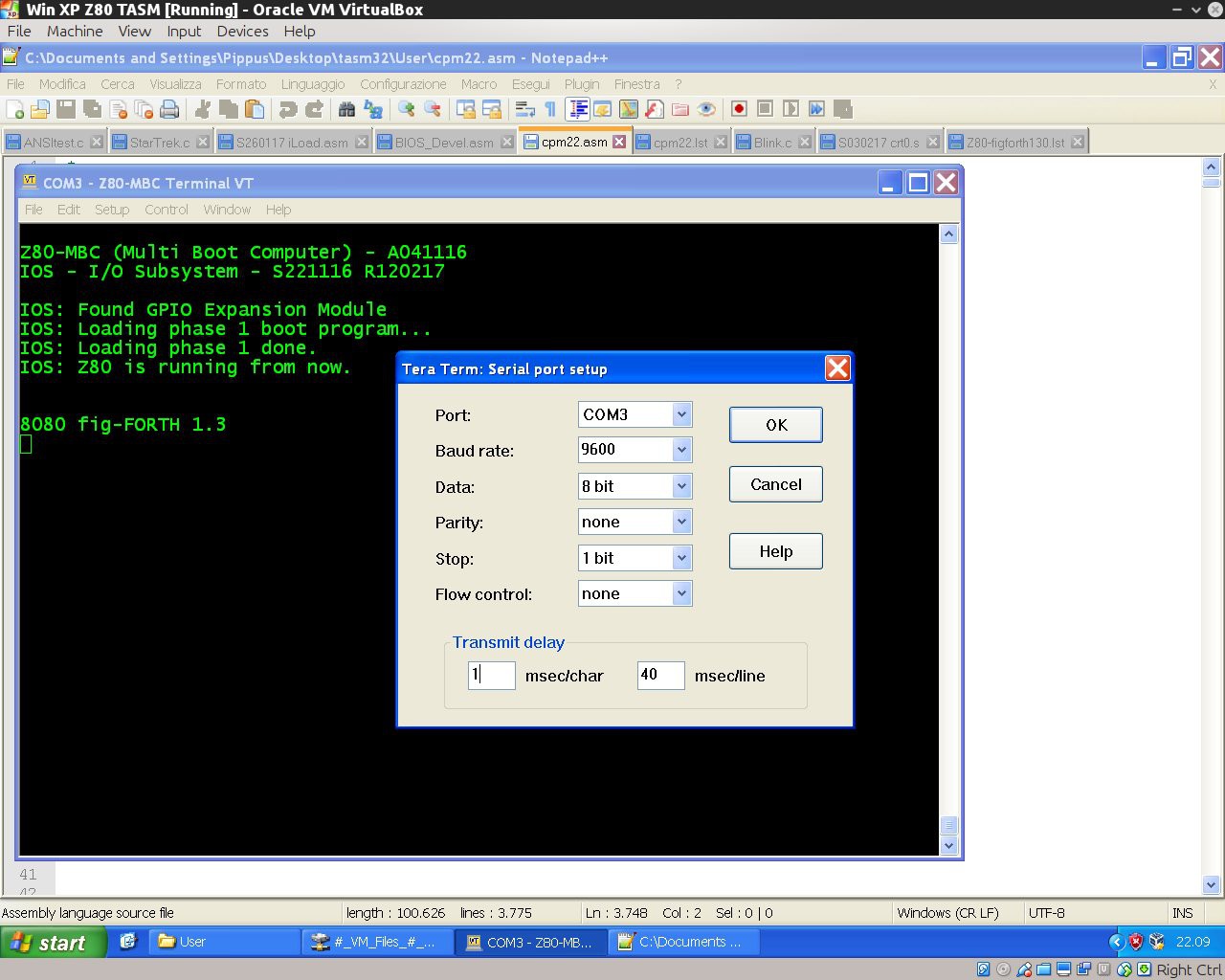
    If you are using Tera Term to send a text file to load a forth source, remember to set up a delay of 1ms for each character (serial port managed by the Arduino bootlader doesn't have any handshaking, so for now this is required to handle the serial stream without errors when sending a text file using a terminal emulator):


    New multi-boot selection


    Now pressing the User key after a reset brings to a new menu to chose the preferred boot mode. During this phase the LED-D0 will blink until you choose the boot mode:


    New name


    As you can see from the previous photos, from this release the MBC acronym changes to "Multi Boot Computer"...

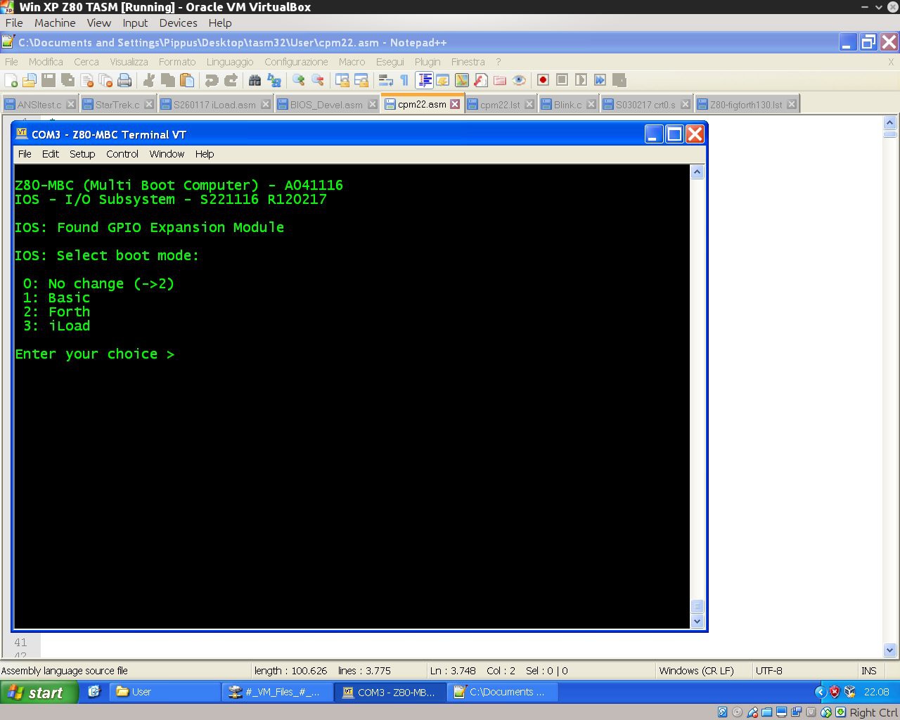
  • An automated C language toolchain

    Just4Fun02/09/2017 at 21:26 0 comments

    Here how set up a toolchain to program the Z80-MBC using the C language. It is based on SDCC (Small Device C Compiler) and uses the same "process" of the previous Assembler toolchain.
    In the following it is assumed the the Assembler toolchain is already set up in a Windows host as described in in the Log: New iLoad boot mode and an automated Assembler toolchain.
    So only the SDCC relevant part is explained here.


    Here it is a short video with the toolchain in action:

    What you need to do:

    1. Create a working directory (or use the previous one) where to store the C sources and the two batch files (C.BAT and L.BAT) in the C_batch.zip file from the File section (if you are using the same assembler working directory overwrite the previous L.BAT);
    2. With a text editor search the line:
      "C:\Program Files\teraterm\ttermpro.exe" /c=3 /BAUD=9600 /w="Z80-MBC Terminal" /m=LoadZ80.ttl
      inside C.BAT and L.BAT and verify that both the path and the COM number (/c=3 means COM3) meet your system;
    3. Download and install SDDC from here;
    4. Download the file S030217_crt0.s from the Files section in the working directory;
    5. Open the DOS command line and give the command: "sdasz80 -o S030217_crt0.s".
      Then rename the generated S030217_crt0.rel as crt0.rel. Copy it in the SDCC directory "C:\Program Files\SDCC\lib\z80" (may be a bit different in your system) overwriting the old one.

    All done!

    As usual close Tera Term before every new upload.

    To check if it is all ok, download from the File section the file C_demo.zip and unzip it in the working directory.
    From the DOS command line give the command: "C Blink.c" to check if all the toolchain works as in the video.
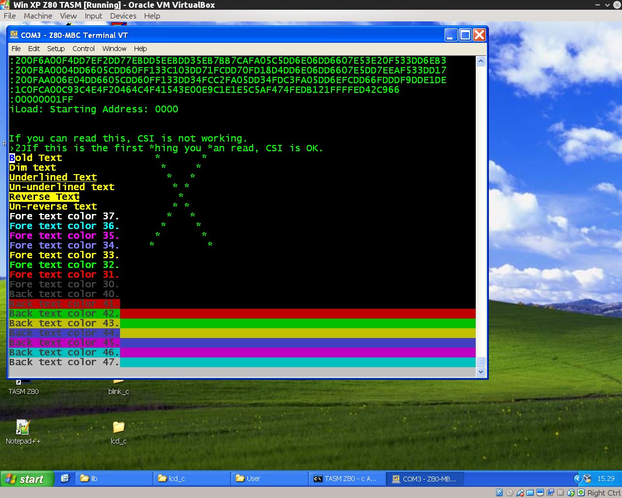
    Try also the other demo ANSItest.c (taken from here) to check the ANSI capabilities of a different terminal emulator or a physical terminal:

    About SDCC

    I'm pretty new to SDCC. The SDCC documentation is 8051 "focused", so the given examples can be misleading if used with an other processor in mind.
    When "porting" SDCC to a target HW, there are 3 things to prepare:

    • customize the crt0.rel file that contains the initialization code for the target system;
    • add to the library the function putchar(char c) to send output to the console;
    • add to the library the function getchar() to read from the keyboard.

    I found the documentation quite missing about how to modify for a custom system.
    In particular in the provided crt0.s example there isn't a needed global declaration of three variables (l__INITIALIZER, s__INITIALIZED and s__INITIALIZER). Without this declaration the code will not compile.
    And to make this customization you need to know how the provided assembler works, but the assembler manual is not provided. So you must find it googling...
    If you are used to the Arduino IDE, read carefully the SDCC manual. This C compiler is a lot more "rude" about types and syntax... (as C standard is...).

    Last minute update

    Just found the assembler and linker documentation here!

View all 14 project logs

  • 1
    Quick instructions intro:

    All the detailed instructions are provided in the "DETAILS" section and in every "LOG".

    Because this project has grown a lot on the way (more than I've supposed at the beginning...) here you can find a short and simple build guide without "navigate" into all the various "LOGs".

    This short guide is referred to the current (at present date 31 August 2017) last "level" of development as described in "A new OS: QP/M 2.71 and a RTC for timestamping".

  • 2
    Add the Atmega32 support in your Arduino IDE:

    The standard distribution of Arduino IDE doesn't have the Atmega32 "core" support files.

    You need to add them from here.

  • 3
    Flash the Atmega32:

    First of all you need to flash the Arduino bootloader into the Atmega32.

    To do this there are a lot of ways. I use a cheap USBASP programmer that you can find "around" for less than 2$.

    Remember to select from Arduino IDE the "Atmega32 8MHz Internal" clock option before flashing the bootloader!!!

View all 6 instructions

Enjoy this project?

Share

Discussions

m.uhlmann.zwickau wrote 09/07/2024 at 12:38 point

Now I got two EEPROMS 1025. I set the first EEPROM on address 51, because the EEPROM on the RTC is on 50.

  Are you sure? yes | no

m.uhlmann.zwickau wrote 08/10/2024 at 09:35 point

Hallo, I have built the Z80-MBC v3 board. All seems working. Can I use the EEPROM on the RTC? Thanks for your work! I like this simple board.

regards Michael from Germany 

Now I have a problem:

a DS1307 modul seems to work, the EEPROM is shown:

---

Scanning GPIO...

Scanning EEPROM Disk...

Z80-MBC (Multi Boot Computer) - A041116

IOS - I/O Subsystem - S221116 R050720

Z80 running at 4Mhz

Scanning RTC...

IOS: Found RTC DS3231 Generic Module (10/08/24 15:36:10)

IOS: Found Virtual Disk Module

IOS: Disk count: 1

IOS: Disk light is OFF

IOS: AUTOEXEC execution is OFF

IOS: Select boot mode:

 0: No change (->1)

 1: Basic

 2: Forth

 3: iLoad

 4: Load OS from Disk 0

 5: Swap Disks 0 and 3 and Load OS from original Disk 3

 6: Toggle disk light (->OFF)

 7: Toggle AUTOEXEC execution (->OFF)

 8: Change RTC time/date

Enter your choice >

---

A DS3231 is not recognized:

---

Scanning GPIO...

Scanning EEPROM Disk...

Z80-MBC (Multi Boot Computer) - A041116

IOS - I/O Subsystem - S221116 R050720

Z80 running at 4Mhz

Scanning RTC...

IOS: Select boot mode:

 0: No change (->1)

 1: Basic

 2: Forth

 3: iLoad

Enter your choice >

---

also another DS3231 from another computer is not working.

What may be wrong?

Found a solution. Solder the address pins and it works!

about prices:

I paid at eBay

PCB 13 €

z80 10 €

ATM32 7€

TC551001 6€

little things 5 €

FT232 cable 10 €

RTC 5€

  Are you sure? yes | no

john wrote 04/12/2023 at 19:55 point

Hey, I built this Z80 MBC, programmed the Atmega and when I boot I see CP/M in the menu but it won't load CP/M, it just keeps trying. Do I have to program CP/M into the Atmega ? Help me out and Thanks

  Are you sure? yes | no

Al Williams wrote 07/18/2020 at 14:39 point

By the way, I have 8 or 9 extra boards (the original ones; v2) if anyone wants them for the postage, let me know. Green silk screen. Can't remember who I had make them but it must have been cheaper to buy 10. 

  Are you sure? yes | no

Aaron wrote 12/19/2020 at 02:29 point

hmmmm wondering if you still have some of the boards

  Are you sure? yes | no

Al Williams wrote 07/03/2020 at 13:28 point

Well, I had a little burst of energy yesterday so new there is a 4-drive CP/M+BIOS file, a utility to dump disks in the iDisk format from CP/M and update to iDisk to support 4 drives. Plus I dumped my WordStar disk B if anyone would like that: https://github.com/wd5gnr/Z80-MBC/blob/master/D1_WORDSTAR.ZIP -- If you restore it to another drive you really need the WSCHANGE program to reinstall WS but it won't fit so you almost need the 4 disks to make this useful unless you are content to leave it on Drive B. All my changes are on my fork: https://github.com/wd5gnr/Z80-MBC -- I know you are more focused on the new board, so I haven't done any pull requests but nothing should break on the original 2 drive system. I also named everything different to avoid conflicts but if you want a pull, let me know and I'll set it up so it is on the same file. The wordstar disk and the diskdump program do not require my firmware upgrades unless you plan to use drives C/D.

I also added a notes.txt file on how to compile different things for next year when I have forgotten ;-) z88dk is very pleasant for compiling CP/M COM files on the PC. Horrible to build, though.

Great fun!

  Are you sure? yes | no

Just4Fun wrote 07/04/2020 at 07:33 point

Could you rename your version as S221116_R040720_Z80.ino so I can upload it here (and link at your repo)?

  Are you sure? yes | no

Al Williams wrote 07/04/2020 at 11:47 point

Done. I was going to send a pull request but it includes too much stuff.

  Are you sure? yes | no

Just4Fun wrote 07/07/2020 at 13:30 point

Hi, just added the new .ino in the Files section with the link to your repo.

  Are you sure? yes | no

[deleted]

[this comment has been deleted]

Just4Fun wrote 06/30/2020 at 16:39 point

Yes, I used TASM for both the CPM22 "core" and the BIOS.

  Are you sure? yes | no

Al Williams wrote 07/01/2020 at 17:52 point

I eventually want to rebuild the BIOS, but since I was in a hurry, I piggybacked two more I2C EEPROMs and changed the Arduino Firmware to deal with them. A quick basic program uses some free space at the top of memory to build up the new disk structures and patch the BIOS to handle the 4 drives. Works great. Next I will probably make a .COM file to do the patch and load it at autoexec! But rebuilding the BIOS will make more sense ;-) 

If anyone is interested, ask and I'll share the files although the patcher is kind of a hack still. 

https://photos.app.goo.gl/tqRrt9xWP5grJS7x5

  Are you sure? yes | no

Al Williams wrote 06/27/2020 at 15:35 point

Hmm maybe replying to yourself deletes your previous comments? Odd. 

  Are you sure? yes | no

Just4Fun wrote 06/27/2020 at 15:56 point

BTW: I've just looked at the PCGET code and it seems the it doesn't rely on standard CP/M calls to access the serial port. This explains why it worked without modify the CP/M BIOS and, probably, the resulting speed is higher than using CP/M calls so it works without increment the rx buffer (may be your serial port is 9600 and not 115200, and this can help too).

  Are you sure? yes | no

Al Williams wrote 06/27/2020 at 16:00 point

Yes, I noticed that as well. I would have converted it to use BDOS, but then it would suffer from the same issues I imagine so that's why I took the route I did. The serial port on mine is 57600 but I never had any issues uploading WordStar and its files. Still, nice to have the buffer and be able to select it for future projects as well.

  Are you sure? yes | no

[deleted]

[this comment has been deleted]

[deleted]

[this comment has been deleted]

Al Williams wrote 06/27/2020 at 15:34 point

Not sure if I accidentally deleted the root post... but to recover the link: document for getting PCPUT, PCGET, a status bit for the serial port, and an increased serial buffer, here: https://docs.google.com/document/d/1xUM6nIeuzou1vhWvedSDNuM72x5ku1T-htuIr2hJKac/edit?usp=sharing

  Are you sure? yes | no

Al Williams wrote 06/26/2020 at 16:10 point

Things are working well. About to try the CP/M. Quick question, though. I notice the SIO isn't a full SIO-88. Port 0 doesn't show the status, but instead shows the user button. Any reason for that? What's more is, I never see SIO characters from inside Basic -- I presume Basic is "eating" the characters?  For example:

10 X=INP(1)

20 IF X=255 GOTO 10

30 PRINT X

40 GOTO 10

This prints nothing. Take line 20 out and you get lots of 255s.

Not a big deal, just curious.

  Are you sure? yes | no

Just4Fun wrote 06/27/2020 at 11:57 point

The serial port "emulation" is very simple. When you read 0xFF it means "no available char", while any other char is a valid one. This was intended as a basic ASCII I/O (so there isn't a status port).

The serial port can be used as an Rx interrupt driven I/O (as in the stand-alone ROM Basic) or as a polled one (as in the CP/M implementation).

May be your example doesn't work because every executed Basic line a char is read by the interpreter to search for an execution break (ESC or CTRL-C, I don't remember).

CP/M: To have a working binary transfer you have to make some little changes in the serial port as you already sorted out (and very probably in the CP/M BIOS implementation too). More, to have XMODEM protocol working, you have to modify the standard Arduino Rx buffer from 64 bytes to 128. This is required because XMODEM uses 128 byte packets and the Arduino serial implementation doesn't support an HW handshaking. Without this modification all the Rx xmodem file transfers will probably fail.

An example how to make the Arduino Rx buffer change in a simple way is described in the "HOW ENABLE THE EXTENDED RX BUFFER FOR XMODEM" paragraph in the Details section of the V20-MBC project page.

  Are you sure? yes | no

Al Williams wrote 06/27/2020 at 12:10 point

Interesting. I haven't extended the buffer but I manged to push WordStar and its files over XModem with no trouble. The way I did the changes did not require mods to the CP/M BIOS because I did not do true emulation of a different board. I kept the I/O addresses the same and just added status bits to I/O 0 and moved the LED out of the way.

As always, thanks for the reply. Great fun!

  Are you sure? yes | no

Al Williams wrote 06/25/2020 at 04:08 point

I finally got around to finishing this up -- mostly. I had started on the breadboard but then got the V2 PCB and got stalled. My problem right now is that Wire.endTransmission hangs if there is no I2C device. So all the code that scans for devices simply hangs. If I comment them out it works fine. I will eventually add the disks and the GPIO -- maybe even the RTC so it probably isn't a problem, but I can't figure out why it just hangs. I do have pull ups on the lines and they show roughly 5V.

The other issue I had to work around was the 8MHz internal clock was too far off to be reliable . I don't know if I botched the OSCCAL or what. It would rarely get a full update and would sometimes miss characters sending out from the Z80. I put a 16 MHz crystal in and changed bootloaders/fuses and all was good.

Well, sort of. At some point my ATMega32A refused to program the high fuse word anymore (TL866 parallel programmer). So that prevented me from getting to the bootloader, but the code was working (except the Wire part). Switching it out with an old Atmega32 (not A) got that working.

Any ideas on the hanging Wire.endTransmission calls?

  Are you sure? yes | no

Just4Fun wrote 06/25/2020 at 08:56 point

Hi, the 8MHz internal osc. issue is "unusual" as nobody reported this up to now.

About the stalling when no I2C device is connected, this is another "never reported" issue... May be there was a change in the library as some years are elapsed...

But this doesn't sound too much probable to me, as I'm using the same approach in the "new" Z80-MBC2 and V20-MBC FW.

I have an assembled Z80-MBC board somewhere (with no IC as I re-used them...), so I can do a check re-flashing the FW from scratch and see what happens without any I2C device when I've the time to do that, and report here the result.

BTW: If you are interested in this kind of "stuff" may be you could give a look to the Z80-MBC2 (the new version) or V20-MBC projects too...

  Are you sure? yes | no

Al Williams wrote 06/26/2020 at 05:30 point

I2C Mystery solved. Those little resistors are hard to read the color code and I had 4.7 ohm resistors not 4.7K on the pullups. The device couldn't pull down the bus and apparently that hangs the twi/wire library. Now a scan doesn't find things that aren't there and now also finds the GPIO module.

  Are you sure? yes | no

Just4Fun wrote 06/26/2020 at 09:04 point

Great!

BTW the 4.22MHz clock seems to me a bit out of range, as it is the 5.5% more... too much...

  Are you sure? yes | no

Al Williams wrote 06/26/2020 at 12:04 point

Agree. That's why the baud rate was also off. I don't know if I botched the OSCCAL value or if the device was just out of spec.

  Are you sure? yes | no

kpengwin wrote 11/13/2019 at 13:38 point

I know the MBC2 is the focus now, but i'm very confused as to why my MBC-1 rev3 isn't working - basically it finishes the stage 1 bootloader and then does nothing (as far as the serial terminal is concerned) after that.


edit: if anyone else sees this, the fuses on my atmega32a were set incorrectly

  Are you sure? yes | no

Jacob MacLeod wrote 10/06/2019 at 13:11 point

Nice!

  Are you sure? yes | no

Moomin House wrote 06/26/2019 at 04:49 point

Picking this up again -- I had boards made last year and gathered chips and life happened.  Looking at the board, it looks like it's using surface mount capacitors on the back side.  Not having used these before, I'm not sure what physical size of smd components to find.  1812, maybe?  Small but not tiny.  Thanks for any corroboration.

  Are you sure? yes | no

Just4Fun wrote 06/26/2019 at 06:53 point

SMD components are not needed. Only THP...

  Are you sure? yes | no

Moomin House wrote 06/27/2019 at 03:23 point

Thanks for the note back.  Huh.  I'm confused.  I'm looking at my version 3 MBC board and on the non-chip side of the board I see matched pairs of silver square pads labelled C8, C9, C10,C11, and C12.  Each pair of pads has a white rectangle around the pads and there are no holes drilled through the square pads.  Nearby holes are labelled on the chip side of the board as different components.  Looking at the BOM, I see these are supposed to be 0,1uF Ceramic capacitors.


I haven't found a picture of the back side of an assembled board to see how other folks did this.  Maybe I got the wrong board made up?

Any hints or tips appreciated.

  Are you sure? yes | no

Just4Fun wrote 06/27/2019 at 13:23 point

The Z80-MBC you have is the "old" version. The new one is the Z80-MBC2.

  Are you sure? yes | no

Moomin House wrote 06/29/2019 at 20:30 point

OK, thanks.  I'll get one of the newer boards and start building that.

  Are you sure? yes | no

WestfW wrote 07/05/2019 at 07:45 point

The PCB I did has "extra" SMT capacitors on the back side of the board, because you can never have too many bypass capacitors, and because some people have stock of SMT caps and find them easier to solder.
The board works fine with only the TH caps installed.   It should work fine with only the SMT caps installed.  If you do fussy noise analysis and detect flaws, you can decide to sprinkle both on there, with varying values.  :-)
They're 1206 footprints.  Sort of unusually large for SMT caps, these days, but oh well.

As the project creator said, the Z80-MBC2 is a newer version...

  Are you sure? yes | no

Adrian Wallaschek wrote 06/22/2019 at 11:00 point

One thing I do not get, apparantly I miss something. The description says "with a 128KB banked RAM for CP/M 3".  Now looking at the schematics (Files section), the A16 of the RAM is grounded, making it a total of 64kB. What did I possibly miss? Is the schematics outdated?

  Are you sure? yes | no

Just4Fun wrote 06/22/2019 at 17:09 point

You are on the wrong project page... :-)

This is the previous Z80-MBC, not the Z80-MBC2 you are referring to.

Look here: https://hackaday.io/project/159973

  Are you sure? yes | no

william.huskey wrote 02/11/2019 at 04:53 point

built the bread board, get from the armega..  

Z80-MBC (Multi Boot Computer) - A041116
IOS - I/O Subsystem - S221116 R100218

IOS: Loading phase 1 boot program...
IOS: Loading phase 1 done.
IOS: Z80 is running from now.

but nothing after that.. logic probe shows activity on memory address and data busses 

may be the memory chips I have are not really cmos...  DS2139y-150+ ..   but I would think I would get some other out put.. 

  Are you sure? yes | no

william.huskey wrote 02/12/2019 at 10:17 point

more output from debug 

: I/O READ operation requested - DATA: 03 00000011 ADDR: 02 00000010
IOS: I/O READ operation requested - DATA: CD 11001101 ADDR: 02 00000010
IOS: I/O READ operation requested - DATA: DA 11011010 ADDR: 02 00000010
IOS: I/O READ operation requested - DATA: 04 00000100 ADDR: 02 00000010
IOS: I/O READ operation requested - DATA: C1 11000001 ADDR: 02 00000010
IOS: I/O READ operation requested - DATA: E5 11100101 ADDR: 02 00000010
IOS: I/O READ operation requested - DATA: 2A 00101010 ADDR: 02 0000

IOS: I/O READ operation requested - DATA: 23 00100011 ADDR: 02 00000010
IOS: I/O READ operation requested - DATA: EB 11101011 ADDR: 02 00000010
IOS: INT operation (nothing to do)

  Are you sure? yes | no

william.huskey wrote 02/19/2019 at 22:41 point

it was memory.. got it working with cy62256 in case this helps.. used a 2 by 4 shift register use two to make 64k.. this is all just testing the design, and playing.. 

  Are you sure? yes | no

Cyril V. wrote 08/30/2018 at 00:13 point

Just got my PCBs. The solder is black, they look really good.

I have couple to spare. I think to sell 2 for $5 plus shipping. PM me if interrrested.

  Are you sure? yes | no

Just4Fun wrote 07/22/2018 at 18:26 point

First Z80-MBC2 IOS release is coming...:

https://farm2.staticflickr.com/1808/43571727791_48473e6662_o.jpg

  Are you sure? yes | no

villaromba wrote 07/24/2018 at 19:40 point

Looking good............ 

  Are you sure? yes | no

Peabody1929 wrote 07/06/2018 at 17:03 point

When can we see the Schematic?

  Are you sure? yes | no

Just4Fun wrote 07/07/2018 at 11:26 point

I'll made a new "Log" here with the link when the "project" page is ready...

  Are you sure? yes | no

Just4Fun wrote 07/06/2018 at 10:02 point

Z80-MBC2 PCB just arrived! Now the fun starts... https://farm1.staticflickr.com/839/29361725228_01ee99a83d_o.jpg

  Are you sure? yes | no

Just4Fun wrote 06/17/2018 at 17:52 point

Just tested the new 3D rendering with raytracing of Kicad 5 RC2. The result is stunning... https://farm2.staticflickr.com/1745/42810522692_58348711fc_o.jpg

  Are you sure? yes | no

Similar Projects

Does this project spark your interest?

Become a member to follow this project and never miss any updates