Close
0%
0%

A 4$, 4ICs, Z80 homemade computer on breadboard

No iron, no cry! Build a mini 4MHz Z80 64kB RAM system with Basic and Forth interpreters, CP/M 2.2, QP/M 2.71, Assembler and C toolchains

Similar projects worth following
This is the Z80-MBC (Mobile Breadboard Computer), a mini 4MHz Z80 64kB RAM system with Basic and Forth interpreters, CP/M 2.2, QP/M 2.71, Assembler and C toolchains.

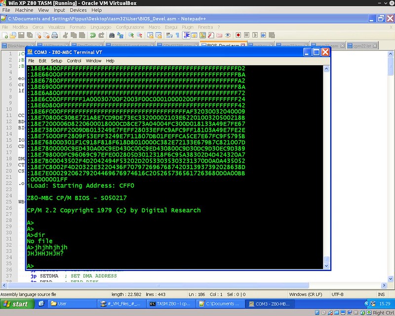
It is a complete development "ecosystem", and using the iLoad boot mode it is possible cross-compile, load and execute on the target an Assembler or C program with a single command (like in the Arduino IDE).

More, it can be easily expanded and it has an "Arduino heart" using an Atmega32A as an "universal" I/O emulator, and can be used and powered with a tablet or smartphone too...

This project has grown a lot on the way (more than I've supposed at the beginning...) and now is renamed as "Multi Boot Computer" and is available on PCB (thanks to Bill Westfield) too.

* * NOTE * * : The new Z80-MBC2 is out!. Check it here: ( https://hackaday.io/project/159973 )

During some surfing on Ebay I realized that with 4$ it is possible to buy enough ICs to build a complete Z80 system that can be done using a breadboard, and taste some flavor of retro computing.... So I did it and here it is the story!

Here is a video with the Z80-MBC in action:

and here with a smartphone (so it is explained the word "Mobile" in his name...) with a common OTG cable (the various test clips in this video were used for some measurements with a Logic Analyzer):


* * HARDWARE OVERVIEW * *


The needed ICs are:

  • Z80 CPU CMOS (Z84C00) 4Mhz or greater ($1.16)
  • Atmega32A ($1.70)
  • TC551001-70 (128kB RAM) ($1.10)
  • 74HC00 ($0.25)

Total cost: $4.21

The wires were taken from salvaged broken LAN cables, and the other components were salvaged from others unused breadboards.

The schematic is attached in the Files section. The MCU Atmega32A is used as universal I/O subsystem, as Eeprom, and as reset and 4MHz clock generator for the Z80 CPU.
Into the Atmega32A it is flashed an Arduino bootloader taken from here , and it is possible to use the Board Manager of the Arduino IDE for that.

Flash the Arduino bootloader at first (with the method you prefer), next you can start to build the whole thing!


Of course I used the Arduino IDE to develop the IOS (I/O Subsytem) that interacts with the Z80 bus and "virtualizes" the peripherals seen by the Z80 CPU.
As oscillator it is used the internal 8MHz Atmega32A oscillator, so no quartz is needed, and from this one is derived the 4MHz clock for the Z80 CPU (so the "Internal 8MHZ osc." bootloader variant must be chosen when flashing the bootloader from the Arduino IDE!).


The 74HC00 is mainly used as RS flipflop to stop the Z80 CPU during I/O operation, giving the needed time to the Atmega32A to interact with the Z80 bus.
The 128kB RAM TC551001 is used only for half (64kB) because the Z80 address space is only 64kB (I've chosen this IC for the low cost).
Note that only the CMOS version of the Z80 CPU can be used here. This because only CMOS version, under given condition that are respected in this schematic, has logical levels compatibles with Atmega32A and 74HC00.


NOTES ABOUT THE COMPONENTS:


You can use any Z80 CMOS speed grade, because the lowest is 4MHz.
The 74HC00 can be substituted with a 74HCT00 if you already have one.
The RAM chip TC551001-70 can be substituted with any suitable 64kB RAM (do not use < 64kB RAM).
The USER led (D5 in the schematic) MUST be blue or white just to be sure that V(forward) is >= 3V.


Here is a video that shows a simple basic program that interacts with the "USER led" and "USER key":


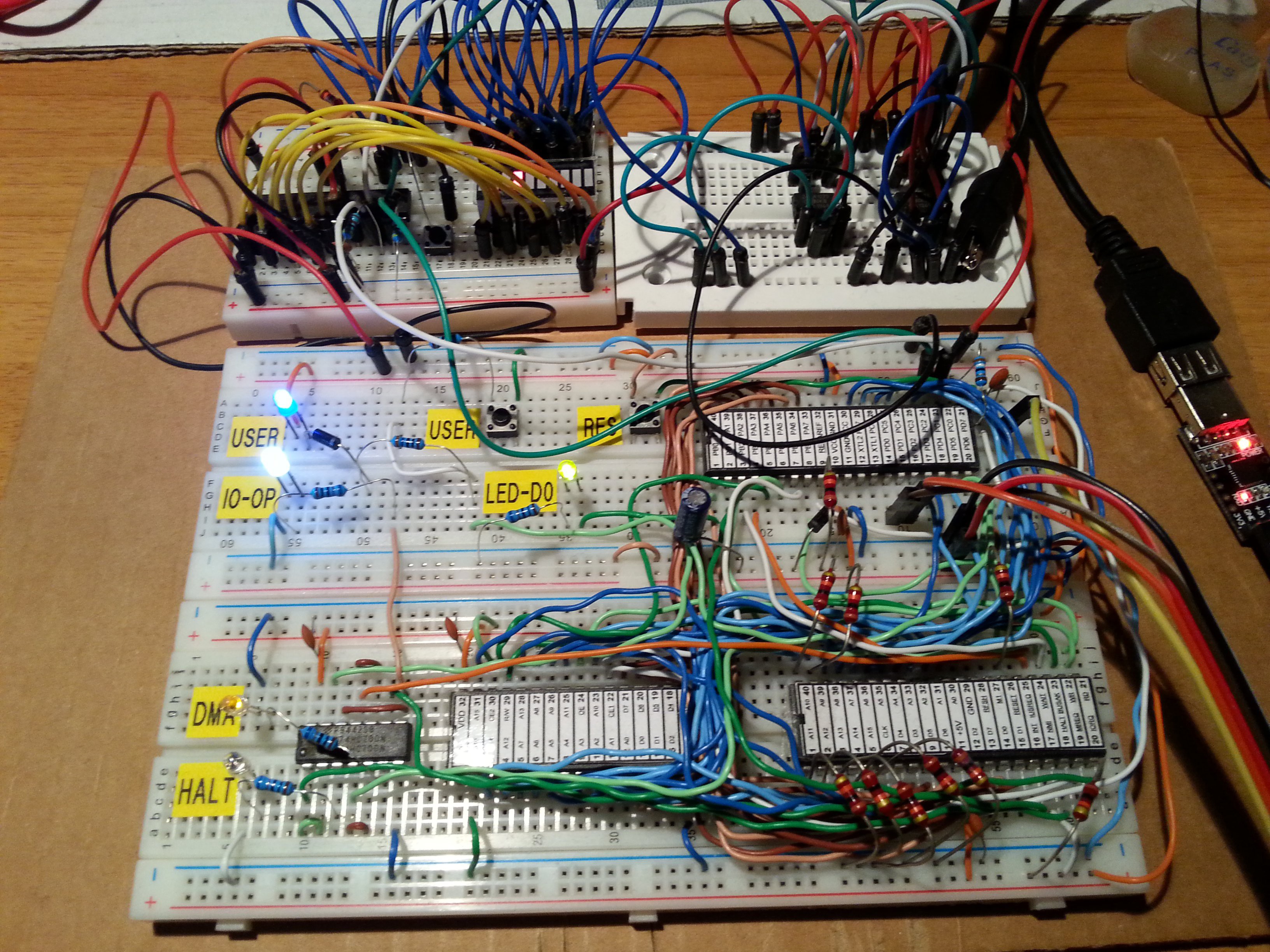
On the breadboard there are others status led: the HALT led turns on if an HALT instruction is been executed and the Z80 CPU is in a Halt state, the DMA led turns on during DMA operations when the Z80 bus is in Hi-Z, the IO_OP led turns on when the Z80 CPU is accessing a I/O virtual device "emulated" by the Atmega32A (as the serial port), the LED_D0 led is the classical "Arduino" led (that one connected to D13 pin on the Arduino Uno) that here is connected with the Arduino D0 pin and is turned on normally as a power on indicator.


The serial port SERIAL-USB (see schematic)...

Read more »

S221116_R050720_Z80.ino

Adds support for 4 drives and others updates. Please see the following repo (created by Al Williams) for new tools, updates and info: https://github.com/wd5gnr/Z80-MBC (by Al Williams)

ino - 165.09 kB - 07/07/2020 at 13:13

Download

S111216.c

TASM Assembler utility.

C Source File - 1.21 kB - 05/15/2018 at 06:05

Download

build.sh

Linux shell script to invoke TASM for WINDOWS (using wine) to assemble Z80 source code and produce a HEX file and a 'C' header file containing the code. Requires TASM 3.2 and wine. See the notes in the script (by Scott).

x-shellscript - 1020.00 bytes - 05/14/2018 at 19:31

Download

optiboot_m32-20mhz.hex

Anyone wishing to overclock the AVR at 20MHz; OptiBoot HEX file for ATmega32/A running at 20MHz (by Scott).

x-hex - 1.31 kB - 05/14/2018 at 18:29

Download

optiboot_m32-8mhz.hex

OptiBoot HEX file for ATmega32/A running at 8MHz (by Scott).

x-hex - 1.31 kB - 05/14/2018 at 18:28

Download

View all 39 files

  • 1 × For the breadboard version see the file "Z80-MBC - BOM.xls" in the Files section
  • 2 × For the PCB version see the file "Z80-MBC PCB version - BOM.xls" in the Files section

  • The Z80-MBC2 is out!

    Just4Fun07/25/2018 at 16:25 0 comments
  • Hardware Fix for the A041116 schematic (USER led and key)

    Just4Fun07/19/2018 at 18:09 0 comments

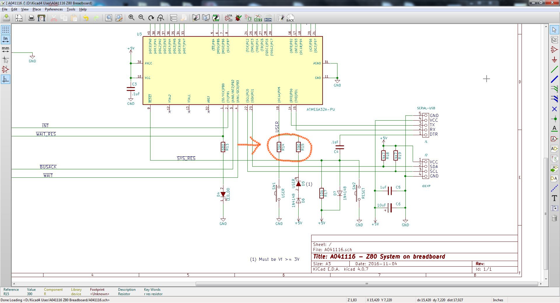
    During some tests on the new Z80-MBC2 I realized that the circuitry of the USER led and key (that is the same used in the Z80-MBC) could cause in some cases an erratic behavior of the USER key (USER key not recognized when pressed).

    The solution is easy, and the fix requires only to change the values of R14 and R15 (see the A041116 schematic) to 390 Ohm (both) as shown:

    Remember that the USER led (D5) must have a forward voltage drop (Vf) of at least 2.7V (e.g. a blue led).

    Please note that this fix is suggested only if you are building a new board or if you are experiencing difficulties with the USER key.

    If you already have a perfect working board there is absolutely no need to apply this fix.

  • Bug fix: the "ghost RTC"

    Just4Fun02/10/2018 at 17:01 0 comments

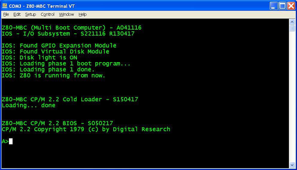
    Reading this Japanese article on a kit sold in Japan to build a Z80-MCB, I realized the presence of a possible bug seeing this two images:

    As you can see, there is a Z80-MCB without any Virtual Disk or RTC attached and in the resulting screenshot the RTC appears present.

    After a quick check I found a little bug in the RTC discovery routine that see a "ghost RTC" when the Virtual Disk is not present.

    So I've uploaded a new "sketch" (S221116_R100218_Z80.ino) that fix the bug.

    Note that if you have the Virtual Disk already installed, there isn't any real need to upgrade.

  • How to make custom Virtual Disk images

    Just4Fun05/29/2017 at 14:29 1 comment

    To do that you need two really powerful tools: Cpmtools to create CP/M disk images and SRecord to manipulate ROM/EPROM images.
    Take in account that the structures of the virtual disk 0 and 1 of the Z80-MBC are different. Disk 0 has the two first tracks reserved for the system image (loaded into RAM by the CP/M loader), instead disk 1 doesn't have this "reservation". This means that the images have a different "structure". More, because disk 0 must have the system image inside the two first tracks, the disk 0 image creation will be different if the OS is CP/M rather than QP/M.
    So to make things easier I've prepared some batch file to simplify the needed operations.
    As for the Assembler and C toolchains you need a Windows host or VM.


    Here all the steps to set up the needed tools:

    1. Create a working directory on your Windows Machine;
    2. Download Cpmtools and unzip in your working directory;
    3. Download last version of SRecord and unzip in your working directory;
    4. Download from the Files section CPMtools-custom.zip and unzip the files into the directory containing the Cpmtool executables (as cpmcp.exe). During the copy overwrite the file DISKDEFS because the new one contains the needed definitions for the Z80-MBC;
    5. Download from the Files section SRecord-custom.zip and unzip the files into the directory containing the SRecord executables (as srec_cat.exe).

    Now you are ready to create your custom image. First create a sub-directory (called e.g. CPM-files) in the cpmtools directory to store all the files to load in the disk image. Check that they fit into the 128kB avaliable space.


    Steps to create a Disk 1 image

    1. Go to the cpmtools directory and with an editor modify/add/delete in the file MakeDisk1.bat the various lines "cpmcp -f z80mbc-d1 %dskfile% CPM-files\xxxxx.yyy 0:xxxxx.yyy" to match the directory in your host (if needed) and all the files to load (xxxxx.yyy);
    2. From the cpmtools directory open the provided DOS command shell and give the following command (I'll use here the name disk1.dsk for the disk image file):
      MAKEDISK1 disk1.dsk
    3. After the execution copy the file disk1.dsk in the SRecord directory;
    4. Go to the SRecord directory, open the provided DOS command shell and give the following command:
      D1TOHEX disk1.dsk
    5. After the execution you will find four files named from disk1_SEG0.hex to disk1_SEG4.hex to upload into the virtual disk with iDisk.


    Steps to create a Disk 0 CP/M image

    1. Go to the cpmtools directory and with an editor modify/add/delete in the file MakeDisk0CPM.bat the various lines "cpmcp -f z80mbc-d0 %dskfile% CPM-files\xxxxx.yyy 0:xxxxx.yyy" to match the directory in your host (if needed) and all the files to load (xxxxx.yyy);
    2. From the cpmtools directory open the provided DOS command shell and give the following command (I'll use here the name disk0CPM.dsk for the disk image file):
      MAKEDISK0CPM disk0CPM.dsk
    3. After the execution copy the file disk0CPM.dsk in the SRecord directory;
    4. Go to the SRecord directory, open the provided DOS command shell and give the following command:
      D0TOHEXCPM disk0CPM.dsk
    5. After the execution you will find four files named from disk0CPM_SEG0.hex to disk0CPM_SEG4.hex to upload into the virtual disk with iDisk.


    Steps to create a Disk 0 QP/M image

    1. Go to the cpmtools directory and with an editor modify/add/delete in the file MakeDisk0QPM.bat the various lines "cpmcp -f z80mbc-d0 %dskfile% CPM-files\xxxxx.yyy 0:xxxxx.yyy" to match the directory in your host (if needed) and all the files to load (xxxxx.yyy);
    2. From the cpmtools directory open the provided DOS command shell and give the following command (I'll use here the name disk0QPM.dsk for the disk image file):
      MAKEDISK0QPM disk0QPM.dsk
    3. After the execution copy the file disk0QPM.dsk in the SRecord directory;
    4. Go to the SRecord directory, open the provided DOS command shell and give the following command:
      D0TOHEXQPM disk0QPM.dsk
    5. After the execution you will find four files named from disk0QPM_SEG0.hex to disk0QPM_SEG4.hex to upload into the virtual disk with iDisk.

    Remember that you...

    Read more »

  • A new OS: QP/M 2.71 and a RTC for timestamping

    Just4Fun05/23/2017 at 15:37 0 comments

    Here is an interesting alternative to CP/M developed by MICROCode Consulting that supports also file timestamping, and it is 100% CP/M 2.2 "compatible".
    MICROCode Consulting has released the original installation files and all the documentation in their site with the "restricted usage" condition, that means free for non-commercial use and for personal use only, so it should be ok for us. Anyway I've sent them a mail about this project.
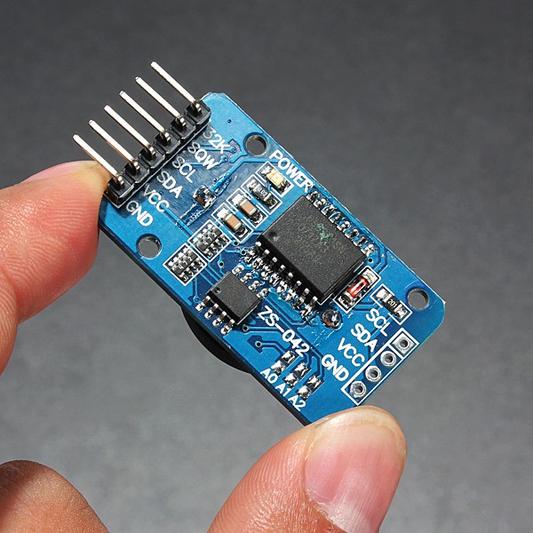
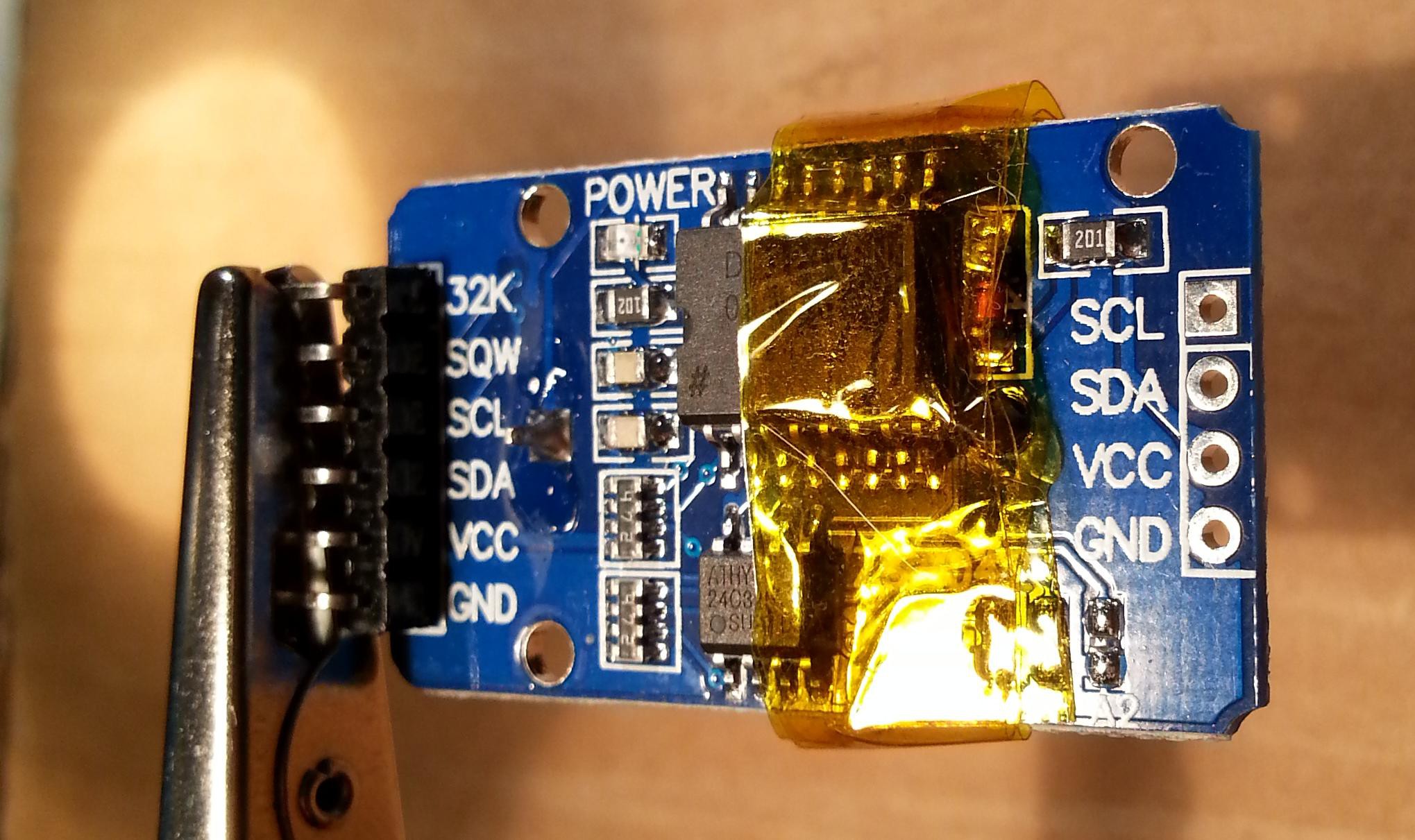
    To enable timestamping you need a DS3231 based RTC module like this one:

    WARNING: these modules can cause battery "explosion"! How to fix it

    This cheap modules have a trickle charging circuit that may cause the "explosion" of the battery if you use a standard CR2032 cell. More, it can damage also a rechargeable LIR2032 cell (see this thread). So the safer thing is "disable" the trickle charging circuit (a CR2032 can last 5/10 years, so there is no practical need to a rechargeable battery, after all...).
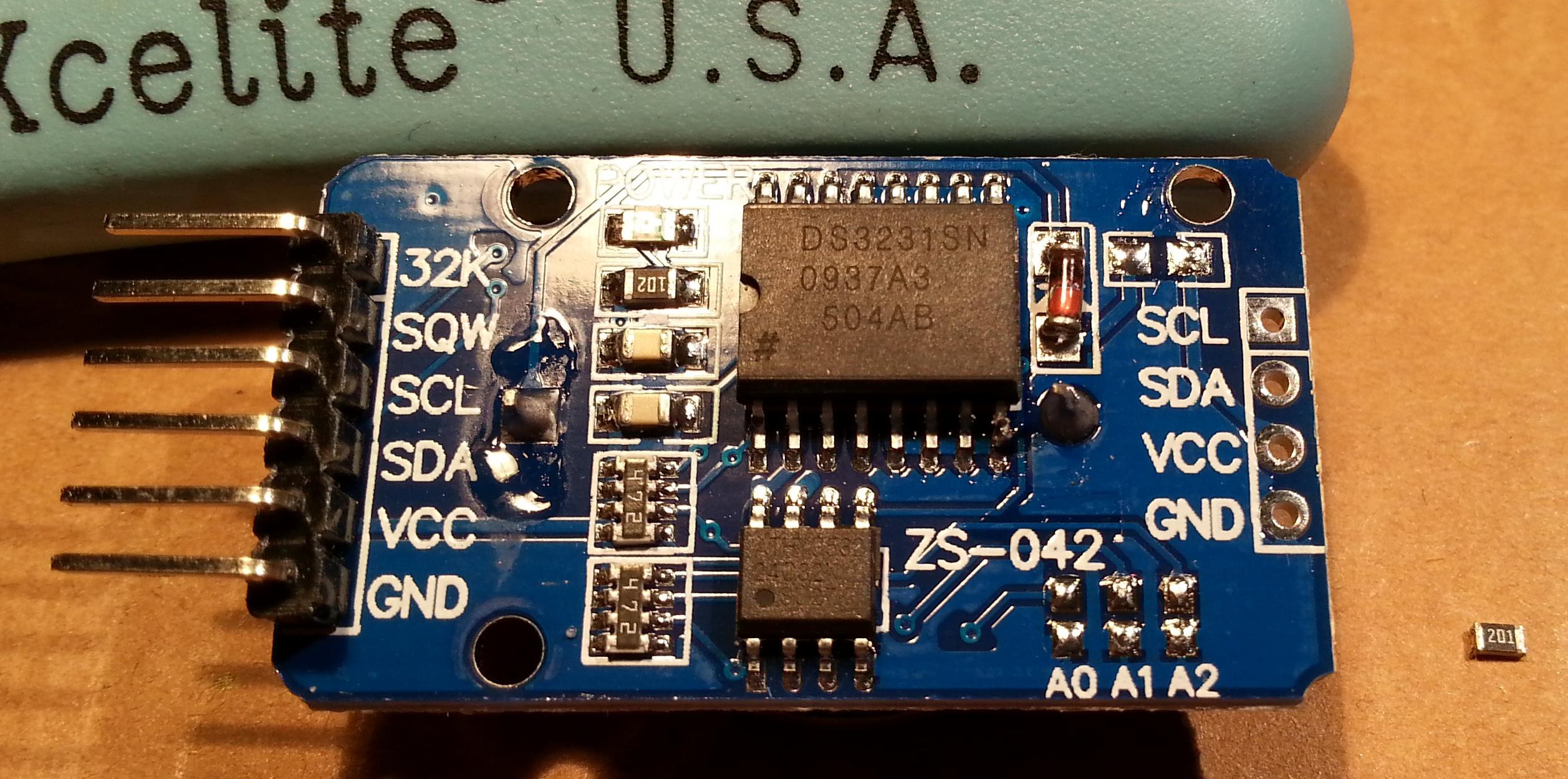
    To avoid any charging current flowing into the battery you can take away the series limiting 200 Ohm resistor (or cut the trace). Alternatively you can take away the red diode, or destroy it (it is in series with the 200 Ohm resistor). In the following photo you can see the module with some Kapton tape (used as thermal barrier) before to desolder the 200 Ohm resistor (on the right marked as 201) with an hot air gun:

    And here after the desoldering:

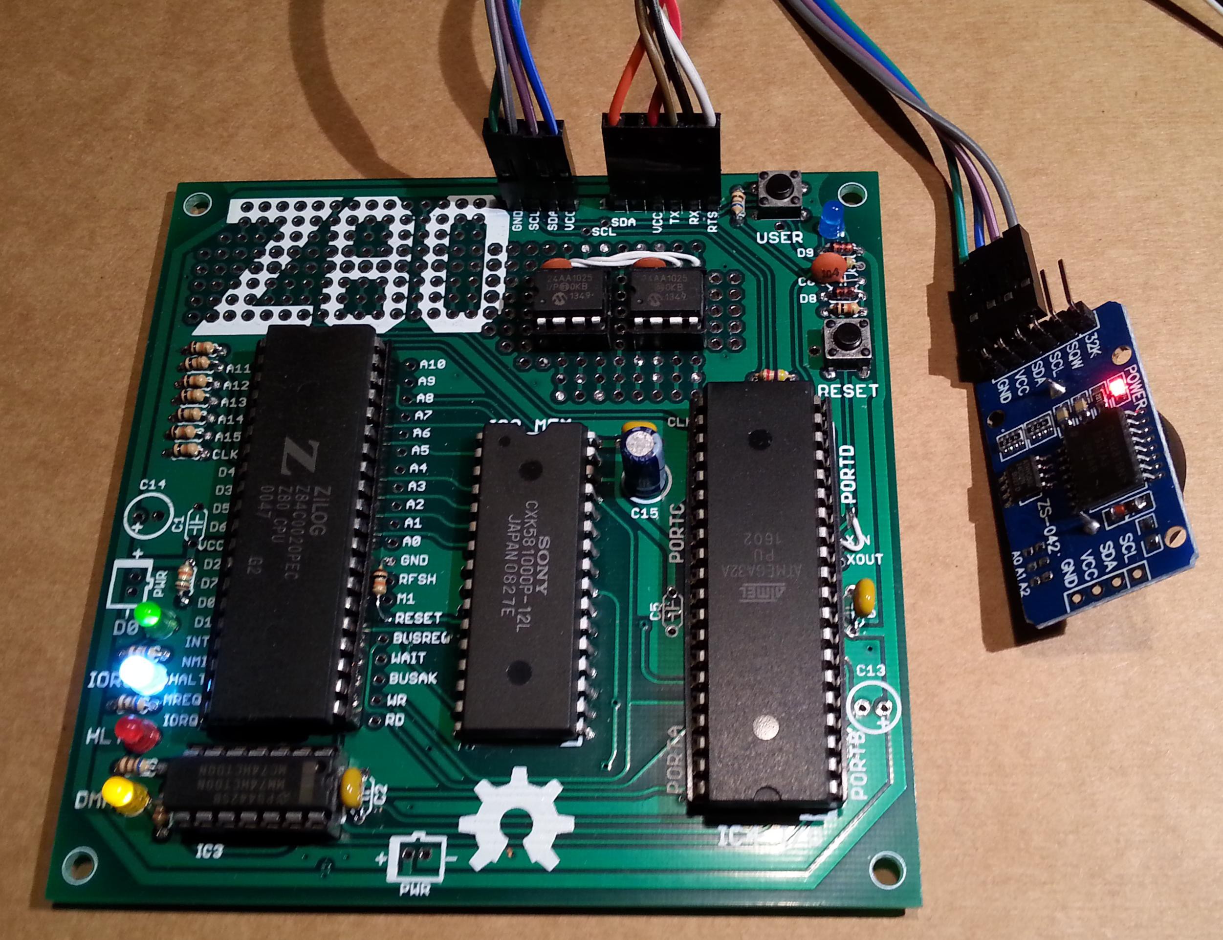
    Now the module it's safe and a CR2032 can be used. To connect it use the SCL/SDA/VCC/GND terminals and connect them at the corresponding pins of the IOEXP/I2C connector of the Z80-MBC (pay attention because the position of the signals is different):

    QP/M quick set up guide

    The setup is quite similar to those used to install CP/M. The Assembler automated toolchain must be already set up and the Virtual Disk Module present.

    Here all the steps:

    1. Connect the DS3231 module (with the CR2032 battery inside);
    2. Update the IOS using the new file S221116_R100218_Z80.ino in the File section;
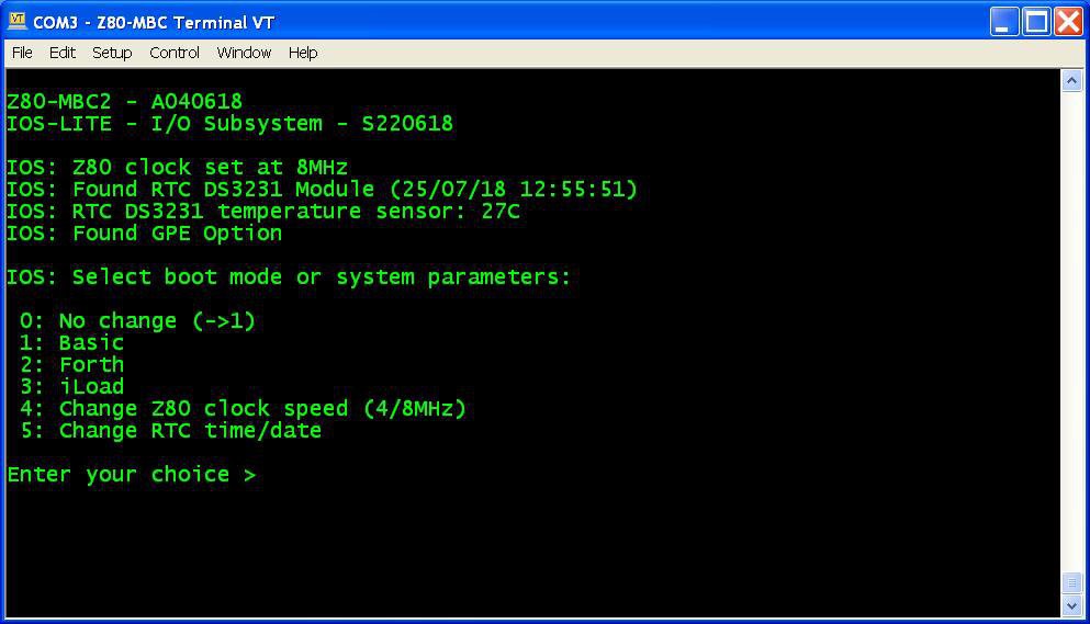
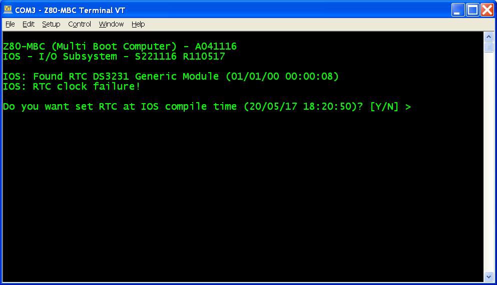
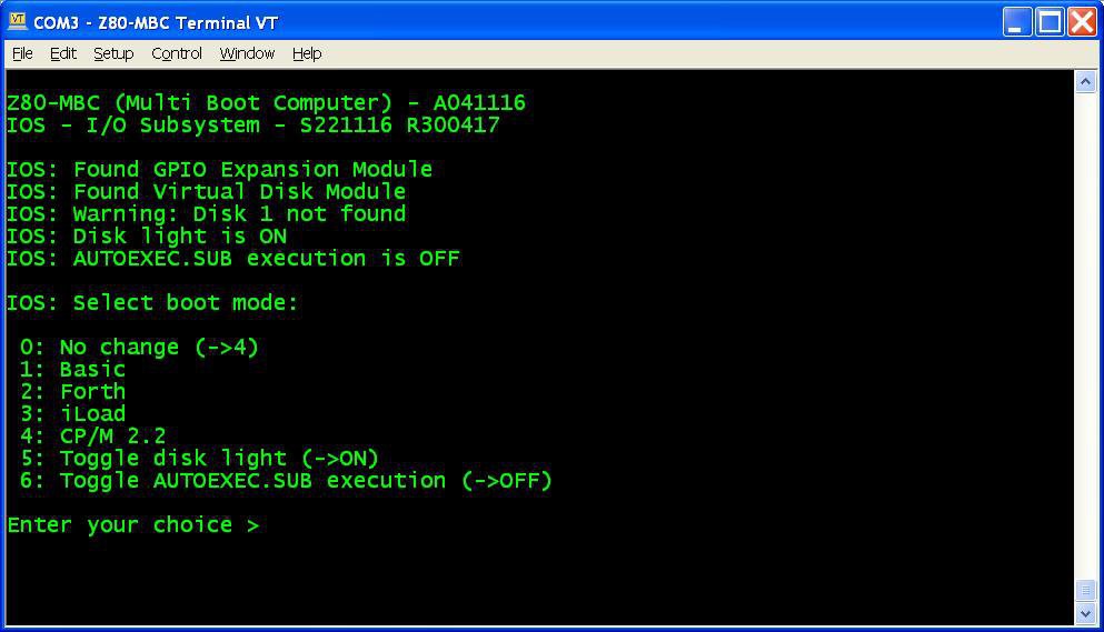
    3. Reboot the Z80-MBC and from a terminal emulator you'll see this:
      Press Y. If you are enough fast you have the RTC set up with the right date/time taken from the sketch compile time (if you are lazy like me you'll find this very handy...). In any case it is possible adjust the date/time manually too from the boot selection menu;
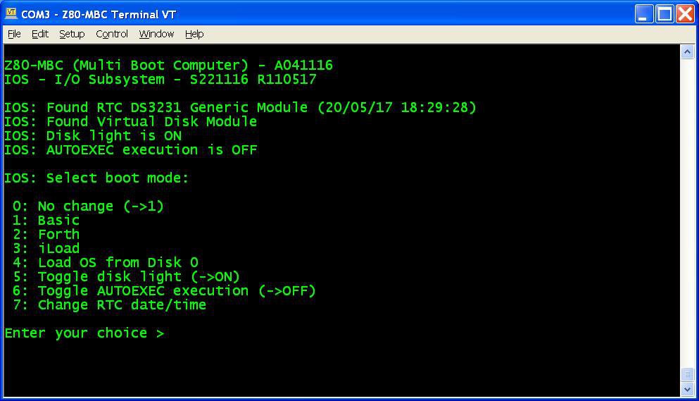
    4. Reboot the Z80-MBC again and select the iLoad boot mode;
    5. From the File section download the file "QPM271_DiskPack.zip", unzip it in the directory used for the Assembler automated toolchain;
    6. Upload the file "iDisk - S250317.hex" to the Z80-MBC using the Dos batch L.BAT (see Assembler automated toolchain) with the command:
      L "iDisk - S250317.hex"
      
    7. When iDisk waits for the input stream, from the Tera Term menu select "File" -> "Send file..." and choice one of the unzipped .hex file from QPM271_DiskPack.zip;
    8. Repeat step 7 for all the four files;
    9. Press the Reset button on the Z80-MBC and enter into the boot selection menu and select 4 to load the OS from disk 0 (and select the disk light ON if not already done, to have an idea of the behavior):

    NOTE: as already noticed, if you experience errors during the serial upload increase the delay after each line from the Tera Term menu (Setup -> Serial port -> Transmit delay -> msec/line). In my VM I set up a 90ms delay. This is due because Arduino serial port doesn't have any handshaking.

    Now you have QP/M 2.71 up and running, but you need further operations to enable the file timestampig (as stated in the QP/M Installation Guide):

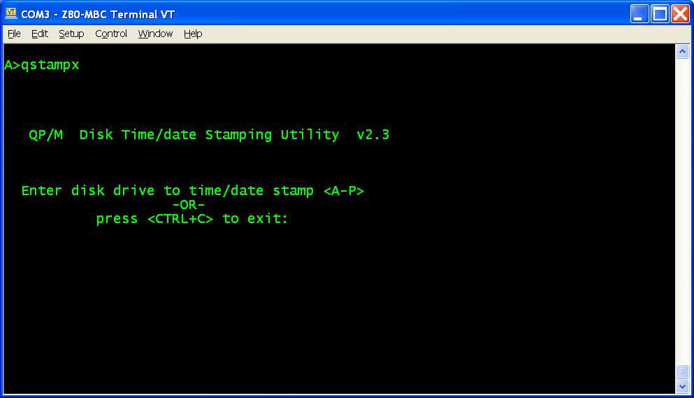
    1. To enable file disk timestamping it is necessary run the utility QSTAMPX from A:
      and do the "disk timestamping" for both A: and B: disks.
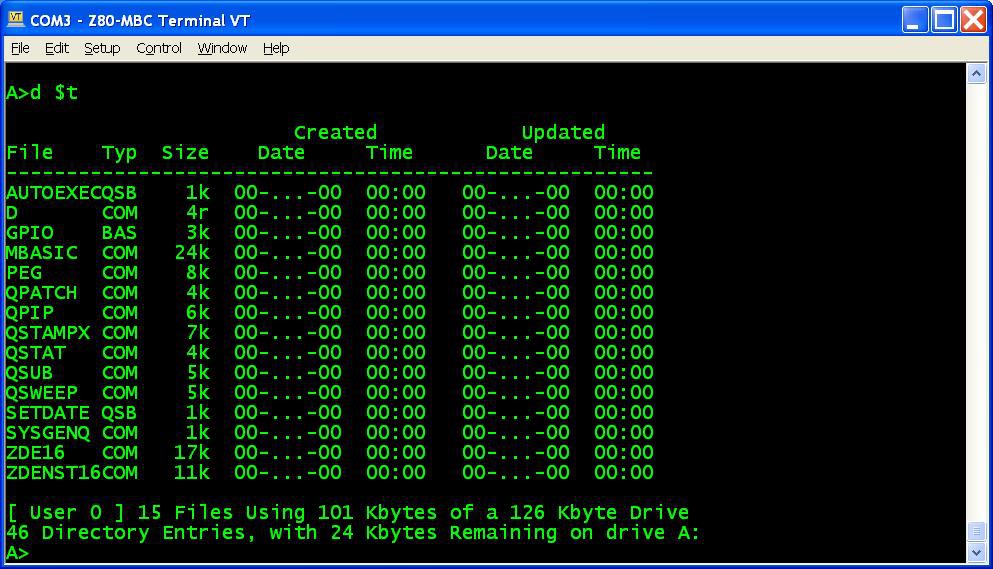
      When done type the command D $T and check that the output is similar to this:
    2. Now to set up a starting date to all files give the command QSUB SETDATE to run a simple batch that I made to do this initialization easily;
    3. Copy the file SETDATE.QSB to drive B: (using the command QPIP B:=SETDATE.QSB) and repeat from B: the same batch (QSUB SETDATE)....
    Read more »

  • AUTOEXEC for CP/M

    Just4Fun05/02/2017 at 16:39 1 comment

    Playing with the Z80-MBC I realized that there was a missing feature: to run a program automatically after the "cold" boot.
    So after some searches I found a way to implement in the BIOS a function similar to AUTOEXEC.BAT for DOS using the CP/M SUBMIT command and a batch file that I called AUTOEXEC.SUB (of course...).
    Editing the AUTOEXEC.SUB file it is possible to run a sequence of commands after the cold boot (as with AUTOEXEC.BAT for DOS), and it is possible enable or disable the execution of the AUTOEXEC batch file from the IOS boot selection menu (but this isn't possible with DOS...).


    AUTOEXEC for CP/M quick set up guide

    You must have CP/M 2.2 already up and running (see CP/M 2.2, iDisk and a new IOS), and you can have also only a "single disk" installed (but I recommend the original dual disk configuration), meaning that only U1 (see the A110417 schematic) is populated. Of course the Assembler automated toolchain must be already set up.


    Here all the steps:

    1. Update the IOS using the new file S221116_R300417_Z80.ino in the File section;
    2. Reboot the Z80-MBC and select the iLoad boot mode;
    3. From the File section download the file CPM22SYS_BIOS_S050217_R300417.hex. This file contains only the new CP/M system image for the system tracks of Disk 0, so the "user files" will be left untouched;
    4. Upload the file "iDisk - S250317.hex" to the Z80-MBC using the Dos batch L.BAT (see CP/M 2.2, iDisk and a new IOS) with the command:
      L "iDisk - S250317.hex"
    5. When iDisk waits for the input stream:from the Tera Term menu select "File" -> "Send file..." and choice CPM22SYS_BIOS_S050217_R300417.hex. After the upload iDisk will show a summary, at this point press W to proceed and confirm your choice (as done for the CP/M 2.2 installation described in CP/M 2.2, iDisk and a new IOS). Wait until the write and verify phase is completed.
    6. Press the Reset button on the Z80-MBC and enter into the boot selection menu and select 4 for CP/M loader.


    All done!


    NOTE: as already noticed, if you experience errors during the serial upload increase the delay after each line from the Tera Term menu (Setup -> Serial port -> Transmit delay -> msec/line). In my VM I set up a 90ms delay. This is due because Arduino serial port doesn't have any handshaking.


    How use it

    To create or edit AUTOEXEC.SUB from drive A, you can use the ED command or an other editor like the Turbo Pascal editor. In this case remember to terminate the file with a CR, or "strange" things will occur when executing the SUBMIT AUTOEXEC command.
    You can test the execution giving the command SUBMIT AUTOEXEC from drive A (you can omit the extension .SUB inside the SUBMIT command).
    To enable the AUTOEXEC execution after the cold boot change the corresponding state to ON from the usual IOS boot selection menu.
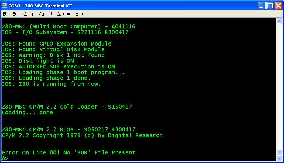
    If the AUTOEXEC is enabled but the AUTOEXEC.SUB file doesn't exist in the drive A, an error will be displayed:


    New "disk packs"

    I've updated both "disk packs" in the files CPM22_DualDiskPack_v2.zip and CPM22_SingleDiskPack_v2.zip with the new BIOS in the system tracks. So if you are installing them for the first time or you need for any reason to reload them, the new BIOS will be installed. I've added an example of AUTOEXEC.SUB too.


    How it works

    The "trick" used was to inject the string "SUBMIT AUTOEXEC" into the CCP (the Command Processor of CP/M) input buffer. The BIOS after the cold boot checks if the AUTOEXEC flag is set in the IOS, and in this case makes the injection. When the CCP starts after the cold boot, it runs this injected command.

    In this video there is an in depth explanation for a "legacy" Altair 8800 clone.

    The CP/M 2.2 and the new BIOS sources are in the file "CPM22 BIOS - S050217 R300417.zip" in the File section.

  • CP/M 2.2, iDisk and a new IOS

    Just4Fun04/20/2017 at 20:36 14 comments

    CP/M 2.2 quick set up guide

    The set up is very simple. I've done an utility (iDisk) to simplify all the needed operations. Of course the Virtual Disk Module must be present, but you can have also only a "single disk" installed (but I recommend the original dual disk configuration), meaning that only U1 (see the A110417.pdf schematic) is populated.
    The Assembler automated toolchain must be already set up.


    Here all the steps:

    1. Update the IOS using the new file S221116_R130417_Z80.ino (or a newer version if present) in the File section;
    2. Reboot the Z80-MBC and select the iLoad boot mode (if not already selected);
    3. From the File section download the file "iDisk - S250317.hex" and copy it into your PC in the directory used for the Assembler automated toolchain . (Do not use the source file "iDisk - S250317.c" because it requires a special compiling option);
    4. From the File section download the file "CPM22_DualDiskPack.zip" and unzip it (for a single disk configuration download the file "CPM22_SingleDiskPack.zip"). Each disk image is divided into four .hex files called "segment" (32kB each) that are named accordingly (e.g. D0XXX_SEG1.hex means the segment 1 of disk 0);
    5. Upload the file "iDisk - S250317.hex" to the Z80-MBC using the Dos batch L.BAT (see Assembler automated toolchain) with the command:
      L "iDisk - S250317.hex"
          
    6. When iDisk waits for the input stream:
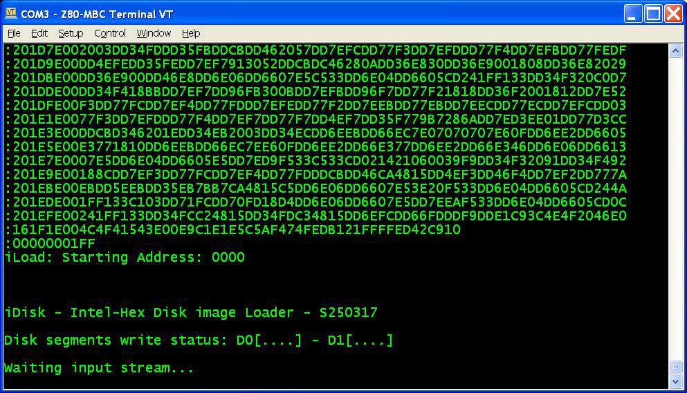
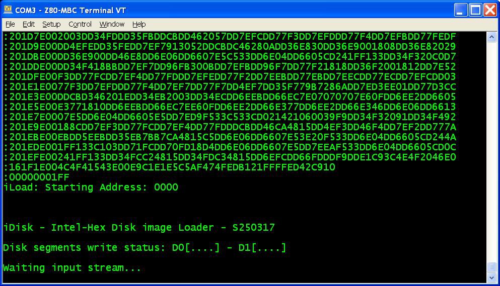
      from the Tera Term menu select "File" -> "Send file..." and choice one of the unzipped .hex file from CPM22_DualDiskPack.zip (or CPM22_SingleDiskPack.zip for a single disk configuration). After the upload iDisk will show a summary:
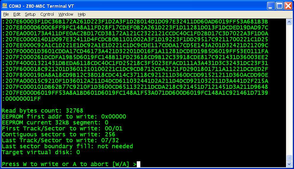
      at this point press W to proceed and confirm your choice.
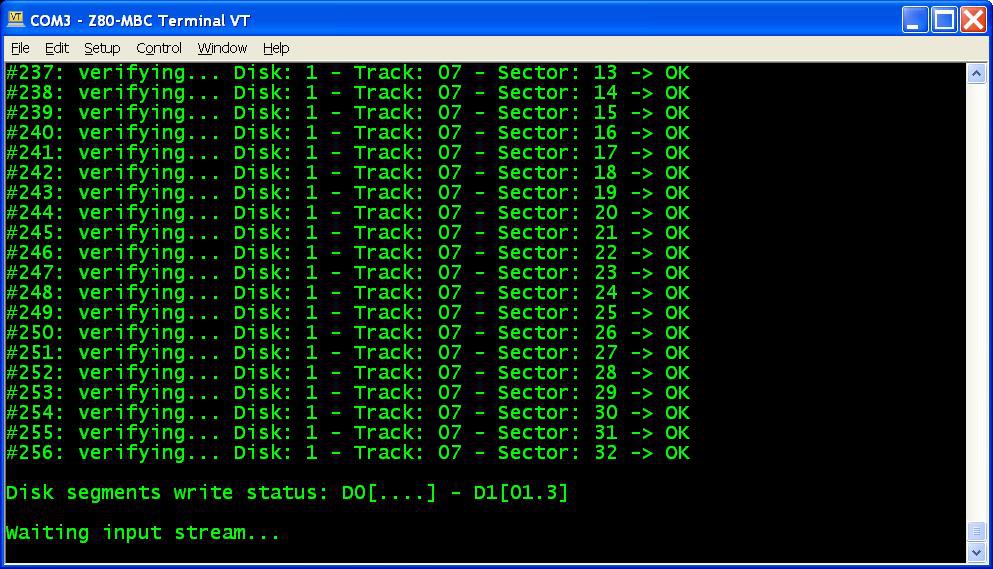
      You don't have to follow any order in the "segments" upload sequence, iDisk will know how to do. To know before each upload what "segments" have been already written into the disks just see the "Disk segment write status":
      in the photo the segments 0, 1 and 3 of Disk 1 have been already successfully written, so you can choose any of the remaining;
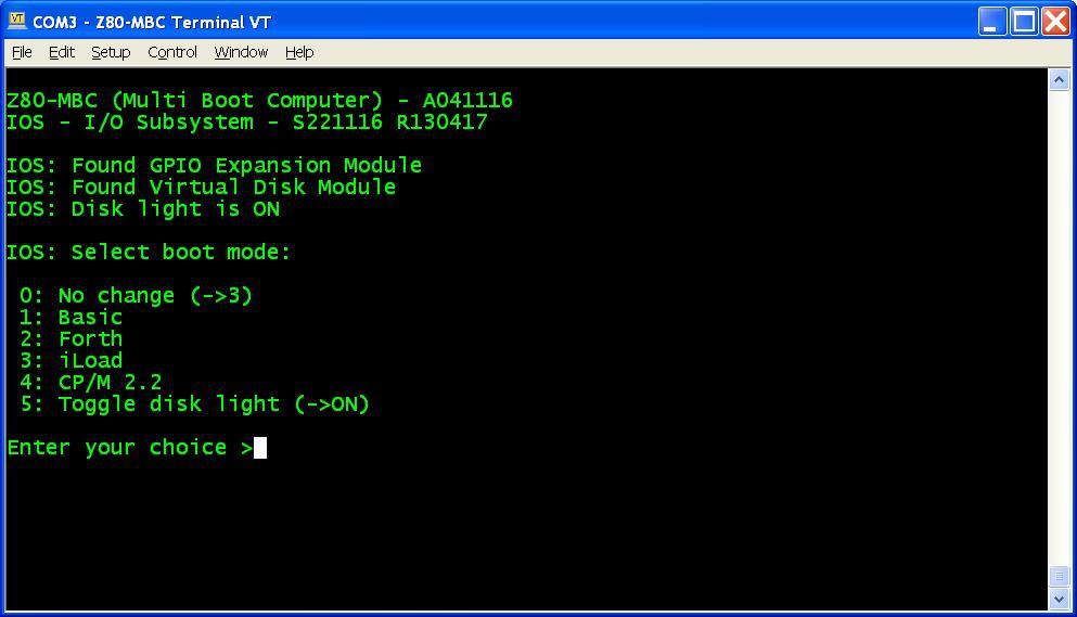
    7. Repeat step 6 for all the eight (or four for the single disk pack) "segment" files;
    8. Press the Reset button on the Z80-MBC and enter into the boot selection menu:
      select 4 for the CP/M loader (and select the disk light ON if not already done, to have an idea of the behavior).
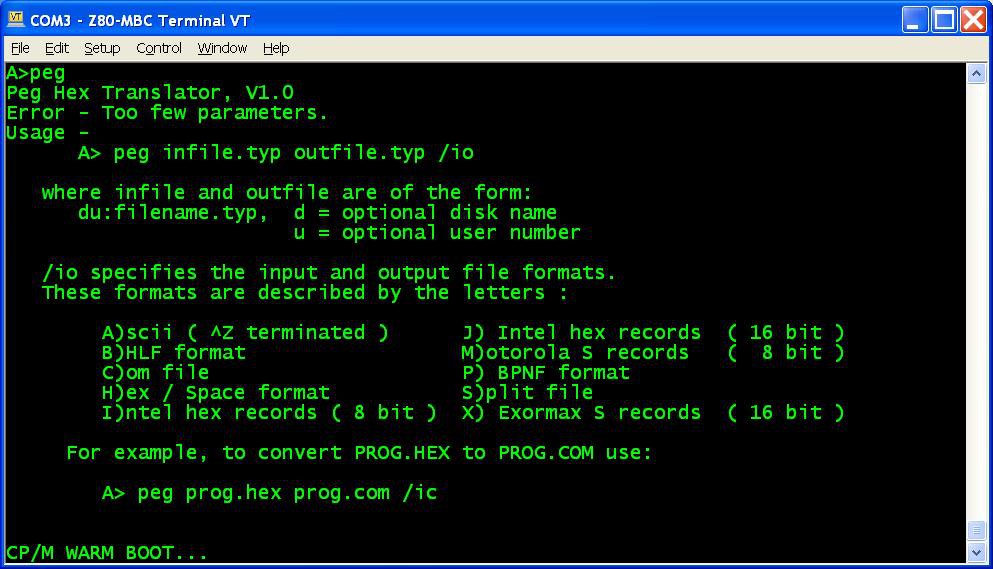
    All done!


    NOTE: if you experience errors during the serial upload increase the delay after each line from the Tera Term menu (Setup -> Serial port -> Transmit delay -> msec/line). In my VM I set up a 90ms delay. This is due because Arduino serial port doesn't have any handshaking.

    Disk speed

    The Virtual Disk Module is based on simple EEPROMs using a 200KHz I2C serial bus. Of course do not expect the same speed of an hard disk with a DMA controller!
    The speed probably is like using the floppy drive of those days...

    Single disk configuration

    You can have also only a "single disk" installed (but I recommend the original dual disk configuration), meaning that only U1 (see the A110417.pdf schematic) is populated.

    In this case you have about 120kB free, because the first two tracks of Disk 0 are reserved for the system image (Disk 1 doesn't have the system image, so all the 32 tracks are used for the file system).

    Because the BIOS is the same and is configured for a dual disk system, if you try to select the "B:" drive you'll get a "BAD SECTOR" error.

    Disk pack contents

    In the disk 0 image there are the various external CP/M commands, the Basic interpreter, the CP/M Assembler and the Macro Assembler.
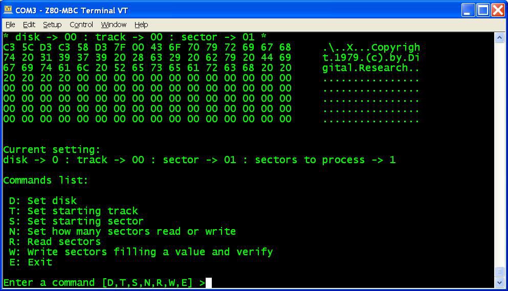
    I've added also D, an alternative DIR command, and PEG, a bin to hex converter (and vice-versa) to exchange files:

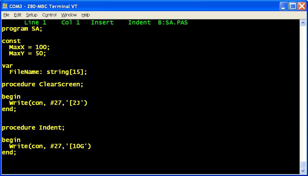
    In the disk 1 image there is the complete Turbo Pascal compiler v3.01A with a sample program (SA.PAS):

    In the "single disk pack" the CP/M Assembler and the Macro Assembler are missing, and the Turbo Pascal is without the installing executable (not a big issue anyway) and without the sample program.
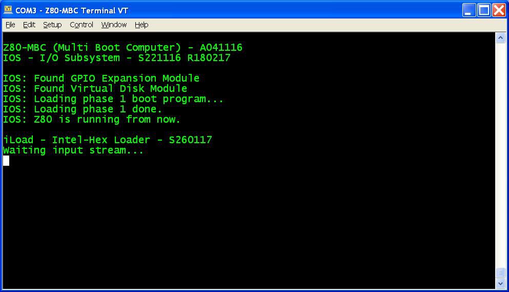
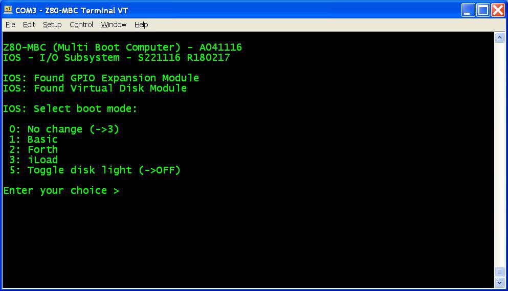
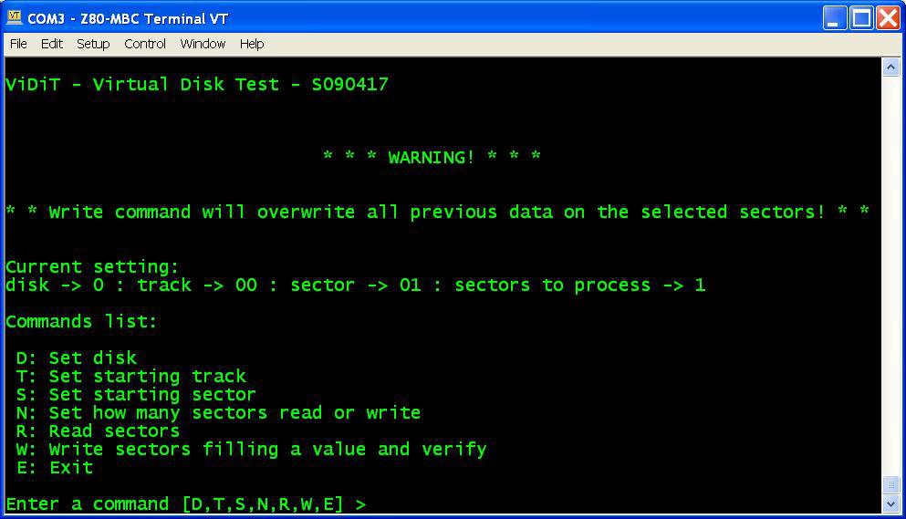
    In a next Log I'll explain how create custom...

    Read more »

  • Virtual Disk Module, a new IOS and ViDiT

    Just4Fun04/13/2017 at 19:37 3 comments

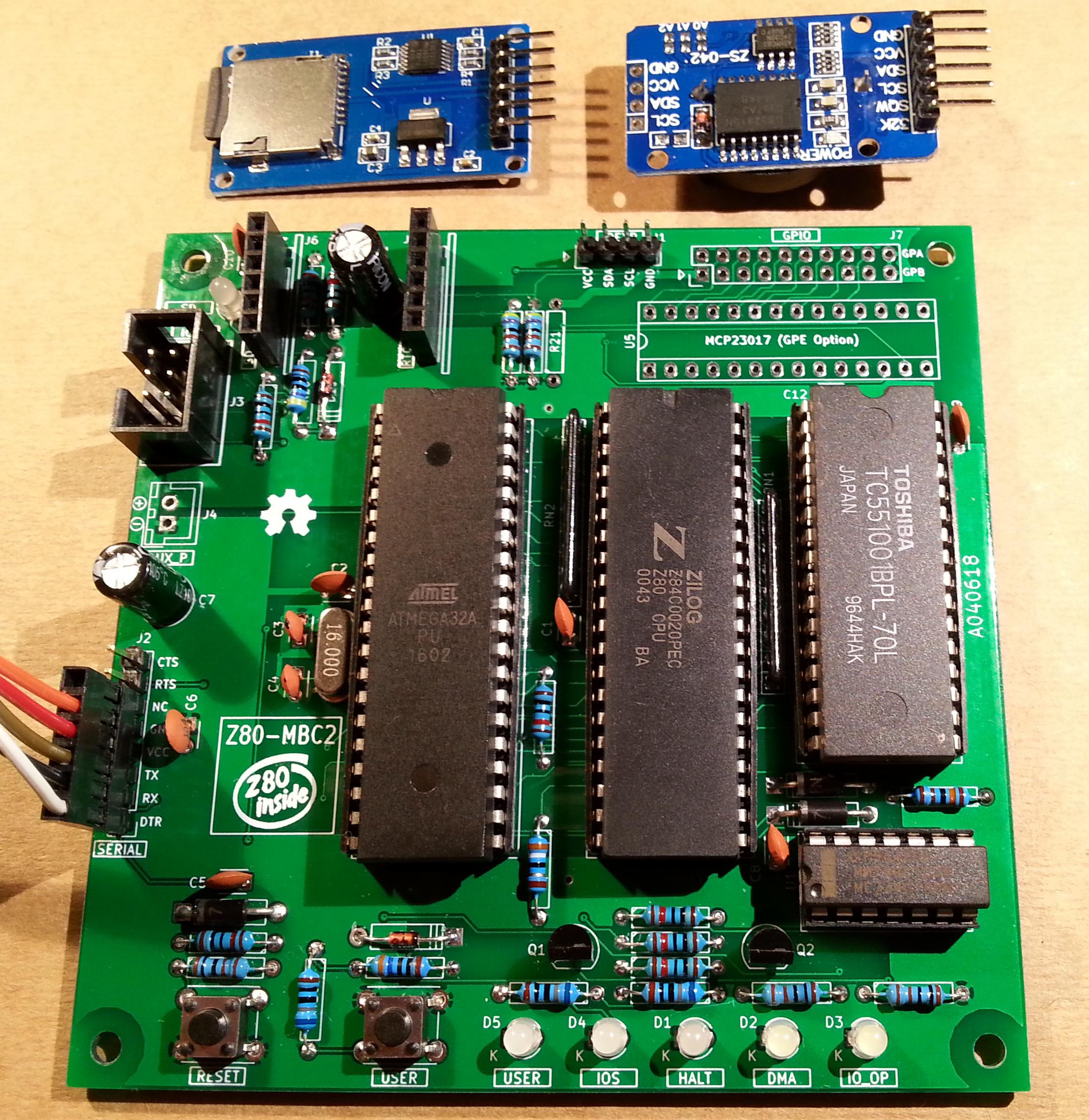
    It's time for a new "module", the Virtual Disk Module! In the photo is that one on the right, near the previous GPIO module.

    In the File section is possible see the simple schematic A110417.pdf with two I2C EEPROM 24LC1025.

    With this module it is possible to emulate two disks of 128kB each (probably like the floppy disk drives of those years).

    Each disk is divided into 32 tracks of 32 sectors. Each sector is 128 bytes long.

    Of course to manage this new HW there is a new release of IOS. The new file S221116_R180217_Z80.ino is in the File section.

    This new IOS checks if the module is present and prints a message if found:

    There is also a new item in the boot selection menu if the virtual disk is found, to use the User led as a disk activity led:

    I suggest to activate this option to have an idea of the behavior.


    ViDiT

    In the File section I've added a simple test program (file "ViDiT - S090417.c") to check the virtual disk. Of course you need to compile it with the C "toolchain":


    About I2C speed

    With this IOS the I2C speed is 200KHz. Note that if you are using a 16MHz external quartz to clock the Atmega32 the I2C speed will be 400kHz. In this case I suggest to lower the two 4k7 pull-up resistors (on SDA and SCL signals) to about 2k2.


    The next Log will bring the CP/M 2.2 up and running...

  • Forth language, new multi-boot selection and a new name

    Just4Fun02/17/2017 at 21:33 4 comments

    Forth


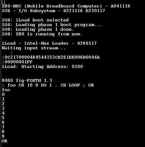
    Thanks to Bill Westfield now we have a new language for the Z80-MBC, the fig-FORTH v1.3 (here the link to the Bill GitHub repository with the source he adapted for the TASM assembler with the needed modifications for the Z80-MBC).

    The acronym "fig" stands for "Forth Interest Group", that was a world-wide non-profit organization (now dissolved) for the promotion of the Forth computer language.
    I've just started to play with this thing, and I must say that it is not the most friendly language I've seen... anyway it is an interesting different approach.

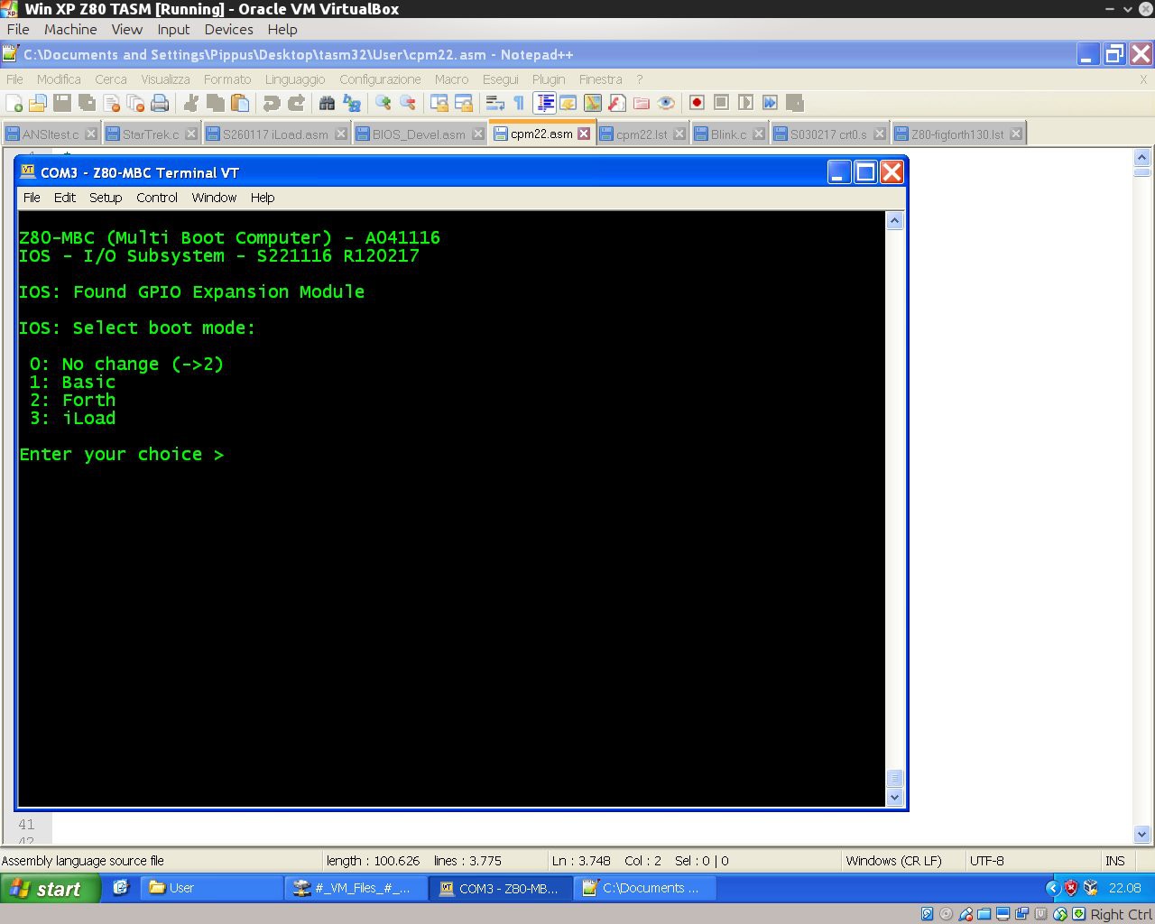
    To enable Forth just upload the new IOS release S221116_R120217_Z80.ino in the Files section, and select the Forth language from the new multi-boot menu (see next paragraph).

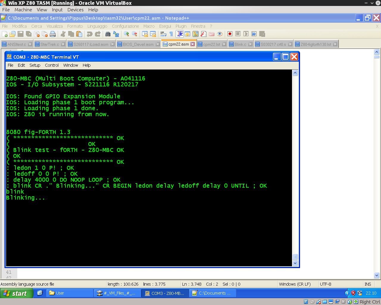
    Here it is a "blink" demo program:

    ( ****************************
    (                     
    ( Blink test - Forth - Z80-MBC
    (
    ( ****************************
    : ledon 1 0 P! ;
    : ledoff 0 0 P! ;
    : delay 4000 0 DO NOOP LOOP ;
    : blink CR ." Blinking..." CR BEGIN ledon delay ledoff delay 0 UNTIL ;

    To execute give the command "blink":


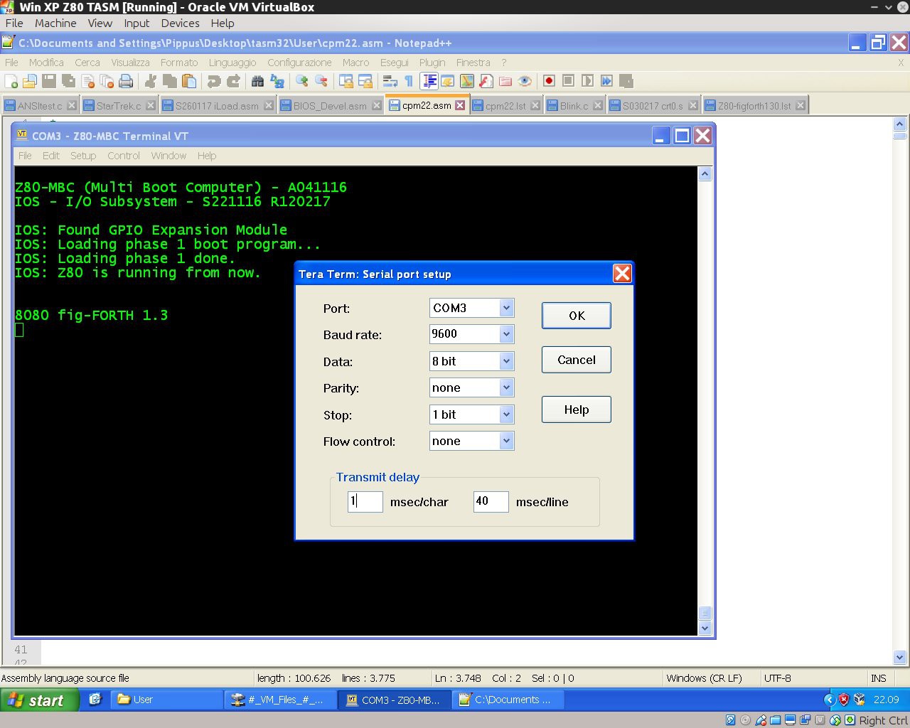
    If you are using Tera Term to send a text file to load a forth source, remember to set up a delay of 1ms for each character (serial port managed by the Arduino bootlader doesn't have any handshaking, so for now this is required to handle the serial stream without errors when sending a text file using a terminal emulator):


    New multi-boot selection


    Now pressing the User key after a reset brings to a new menu to chose the preferred boot mode. During this phase the LED-D0 will blink until you choose the boot mode:


    New name


    As you can see from the previous photos, from this release the MBC acronym changes to "Multi Boot Computer"...

  • An automated C language toolchain

    Just4Fun02/09/2017 at 21:26 0 comments

    Here how set up a toolchain to program the Z80-MBC using the C language. It is based on SDCC (Small Device C Compiler) and uses the same "process" of the previous Assembler toolchain.
    In the following it is assumed the the Assembler toolchain is already set up in a Windows host as described in in the Log: New iLoad boot mode and an automated Assembler toolchain.
    So only the SDCC relevant part is explained here.


    Here it is a short video with the toolchain in action:

    What you need to do:

    1. Create a working directory (or use the previous one) where to store the C sources and the two batch files (C.BAT and L.BAT) in the C_batch.zip file from the File section (if you are using the same assembler working directory overwrite the previous L.BAT);
    2. With a text editor search the line:
      "C:\Program Files\teraterm\ttermpro.exe" /c=3 /BAUD=9600 /w="Z80-MBC Terminal" /m=LoadZ80.ttl
      inside C.BAT and L.BAT and verify that both the path and the COM number (/c=3 means COM3) meet your system;
    3. Download and install SDDC from here;
    4. Download the file S030217_crt0.s from the Files section in the working directory;
    5. Open the DOS command line and give the command: "sdasz80 -o S030217_crt0.s".
      Then rename the generated S030217_crt0.rel as crt0.rel. Copy it in the SDCC directory "C:\Program Files\SDCC\lib\z80" (may be a bit different in your system) overwriting the old one.

    All done!

    As usual close Tera Term before every new upload.

    To check if it is all ok, download from the File section the file C_demo.zip and unzip it in the working directory.
    From the DOS command line give the command: "C Blink.c" to check if all the toolchain works as in the video.
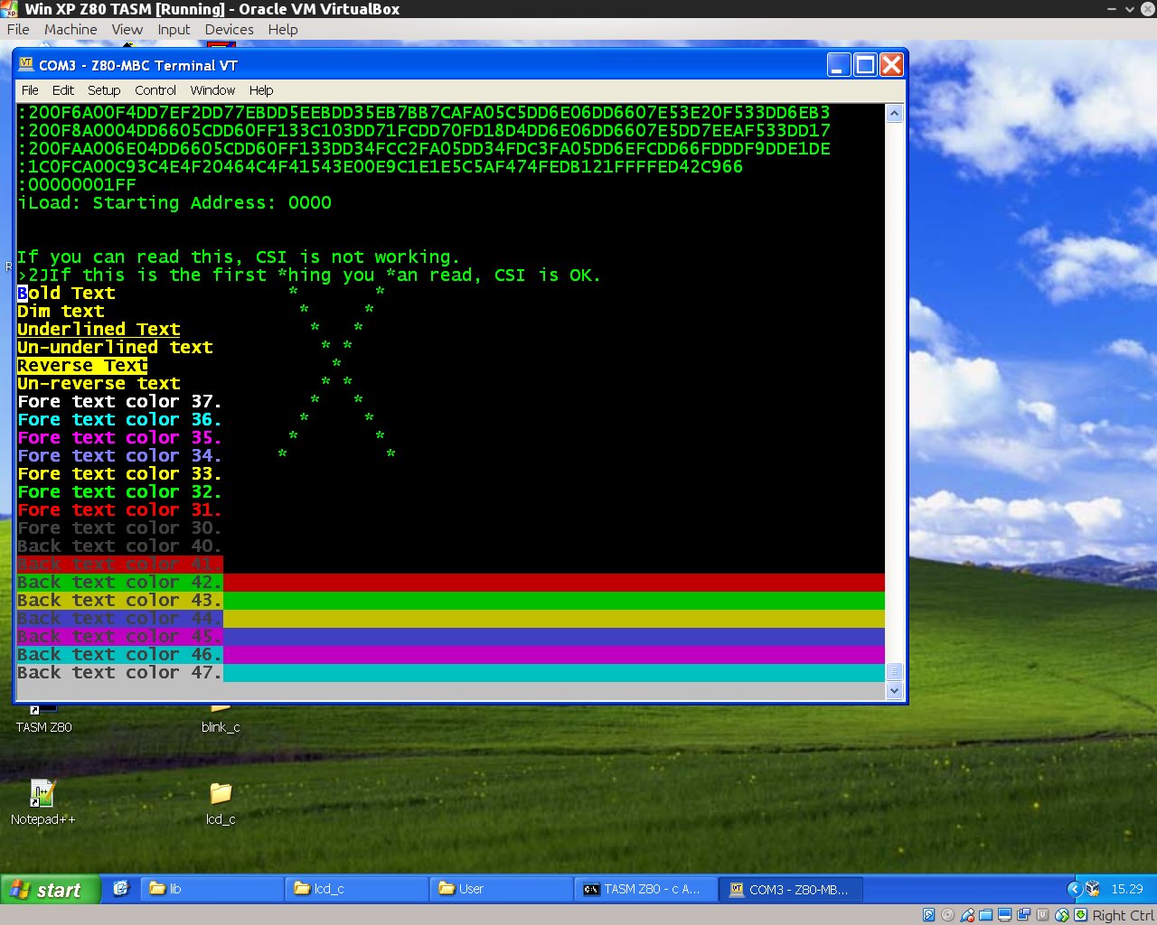
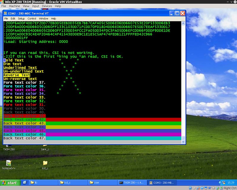
    Try also the other demo ANSItest.c (taken from here) to check the ANSI capabilities of a different terminal emulator or a physical terminal:

    About SDCC

    I'm pretty new to SDCC. The SDCC documentation is 8051 "focused", so the given examples can be misleading if used with an other processor in mind.
    When "porting" SDCC to a target HW, there are 3 things to prepare:

    • customize the crt0.rel file that contains the initialization code for the target system;
    • add to the library the function putchar(char c) to send output to the console;
    • add to the library the function getchar() to read from the keyboard.

    I found the documentation quite missing about how to modify for a custom system.
    In particular in the provided crt0.s example there isn't a needed global declaration of three variables (l__INITIALIZER, s__INITIALIZED and s__INITIALIZER). Without this declaration the code will not compile.
    And to make this customization you need to know how the provided assembler works, but the assembler manual is not provided. So you must find it googling...
    If you are used to the Arduino IDE, read carefully the SDCC manual. This C compiler is a lot more "rude" about types and syntax... (as C standard is...).

    Last minute update

    Just found the assembler and linker documentation here!

View all 14 project logs

  • 1
    Quick instructions intro:

    All the detailed instructions are provided in the "DETAILS" section and in every "LOG".

    Because this project has grown a lot on the way (more than I've supposed at the beginning...) here you can find a short and simple build guide without "navigate" into all the various "LOGs".

    This short guide is referred to the current (at present date 31 August 2017) last "level" of development as described in "A new OS: QP/M 2.71 and a RTC for timestamping".

  • 2
    Add the Atmega32 support in your Arduino IDE:

    The standard distribution of Arduino IDE doesn't have the Atmega32 "core" support files.

    You need to add them from here.

  • 3
    Flash the Atmega32:

    First of all you need to flash the Arduino bootloader into the Atmega32.

    To do this there are a lot of ways. I use a cheap USBASP programmer that you can find "around" for less than 2$.

    Remember to select from Arduino IDE the "Atmega32 8MHz Internal" clock option before flashing the bootloader!!!

View all 6 instructions

Enjoy this project?

Share

Discussions

joel076 wrote 05/04/2017 at 16:32 point

Can i use BS62LV1027PCP55 as ram instead?

  Are you sure? yes | no

Just4Fun wrote 05/05/2017 at 07:03 point

I've given a look to the datasheet and it seems ok.

  Are you sure? yes | no

Cyril V. wrote 05/03/2017 at 12:54 point

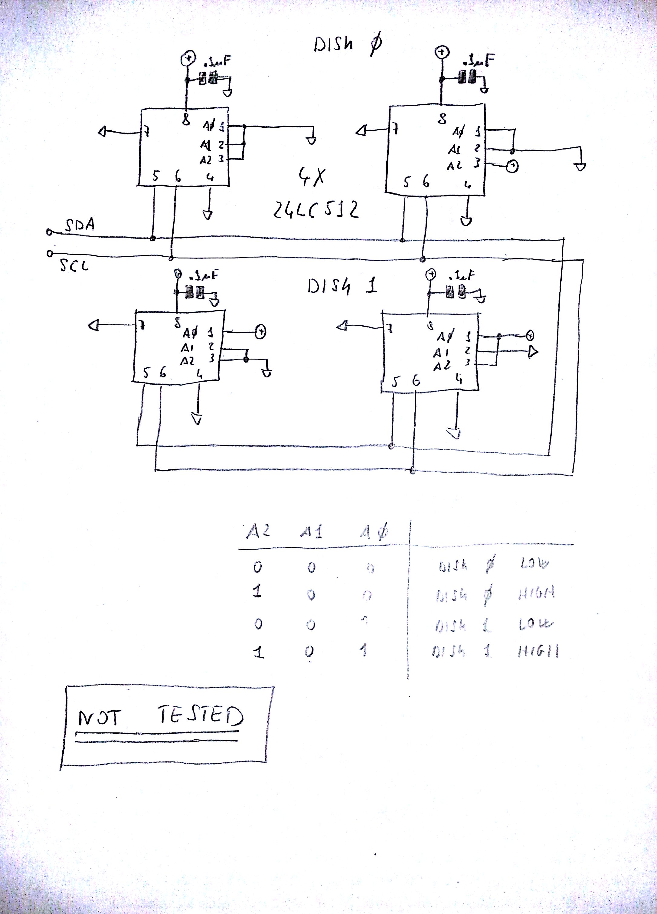
For the Virtual Disk Module can the two 24LC1025 EEPROM be replaced by a lower memory capacity like the 24LC512 or even the 24LC256 (for emulating the two disks of 128kB)?

  Are you sure? yes | no

john wrote 05/03/2017 at 19:15 point

I think it's a bits/bytes thing.  The 24LC1025 is a 128K x 8 (1024K bit)  device, so each chip can hold a 120KB disk image. 

  Are you sure? yes | no

Cyril V. wrote 05/03/2017 at 19:28 point

I can't find cheap 24LC1025/24LC1026 on ebay (more than $20 with shipping for only one chip). Any cheaper alternatives?

  Are you sure? yes | no

john wrote 05/03/2017 at 19:54 point

I picked them up for about $3.50 from Mouser.

  Are you sure? yes | no

Just4Fun wrote 05/04/2017 at 06:41 point

I've given a look to the datasheets. The 24LC256 is a "no-go" because the A15 address bit is missing. The 24LC512 may be... It seems compatible. Of course you need four of them to have an equivalent memory space (or two for a "single disk" system).

Here the the way to use them:


I haven't any 24LC512 so I can't test if it works or not. May be I've forget something... It's only a 2 minutes schematic...

So try it at your risk....

  Are you sure? yes | no

Cyril V. wrote 05/04/2017 at 12:30 point

Great, thank you.

  Are you sure? yes | no

WestfW wrote 04/22/2017 at 09:31 point

I've added Gerbers for the V2 (untested) version of the PCB; something I should have done a long time ago...   https://github.com/WestfW/4chipZ80/tree/master/Gerbers-V2

  Are you sure? yes | no

Cyril V. wrote 04/22/2017 at 18:13 point

Thank you, this is great!

  Are you sure? yes | no

Just4Fun wrote 05/02/2017 at 06:17 point

Hi, I've just seen that in your schematic R16 and R17 have the values swapped (should be R16 = 680 and R17 = 360). Anyway this is not a big issue, and there shouldn't be any "visible" problem...

  Are you sure? yes | no

WestfW wrote 09/22/2017 at 23:45 point

Hmm.   I don't really understand the intended operation of the whole "user" LED/Switch Circuit.  I'd think that if the pin is an output, outputting LOW turns on the LED.  If you want to read the switch, you momentarily switch the pin to an input using either the internal pullup or counting on the tiny current through the LED to act as pullup, and you'll read low if the switch is pressed (which will also light the LED.)   But this would all be true regardless of the resistor ratios (mostly), and Vf of the LED.  Couldn't we eliminate the extra diode and the resistor in series with the switch...

  Are you sure? yes | no

villaromba wrote 04/20/2017 at 09:18 point

Virtual Disk - works great & exactly as described !! Thank you ...  Is/will it be possible to save BASIC & Forth progs to the virtual disk, now or in the future? Looking forward to CP/M post

  Are you sure? yes | no

Just4Fun wrote 04/20/2017 at 12:47 point

The current BASIC & Forth interpreters can't use the virtual disk.

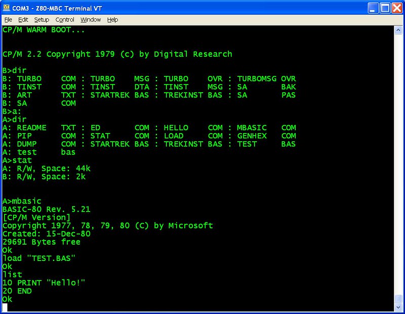
Inside the CP/M "disk pack" there will be the Basic-80 interpreter that is an upgrade of that one used before (and 100% compatible), with the Load and Save function of course, and a lot more. So there will not be any reason to use the "stand-alone" version anymore.

About the fig-Forth 1.3 it has inside a sort of disk system, but:

* is totally not compatible with CP/M file system;

* is incompatible with the Z80-MBC Virtual Disk (until modify the source).

So it probably will be better use a CP/M forth compiler...

  Are you sure? yes | no

john wrote 04/27/2017 at 11:56 point

For some reason I couldn't reply to your post below, but no - I didn't have any trouble getting the disk segments to load (with the EOL delay added).  Everything worked as advertised.

  Are you sure? yes | no

Just4Fun wrote 04/27/2017 at 12:20 point

Ok, thanks!

BTW: thinking to add a sort of AUTOEXEC-like function...

  Are you sure? yes | no

john wrote 04/26/2017 at 23:30 point

I just got this built and working, and as Just4Fun said, using mbasic inside of CP/M does let you load and save to disk.  I was able to paste in the Star Trek code and save it to disk.  I did have some weirdness with case of the filenames though.  I initially saved from mbasic in lowercase and then back in CP/M, couldn't ERAse or otherwise manipulate the file.  With caps lock on and everything in uppercase in mbasic, everything seemed to work fine.

  Are you sure? yes | no

Just4Fun wrote 04/27/2017 at 06:32 point

I think that the MBASIC "lowercase" behavior was intentionally wanted. I had the same behavior using a simulator so it is not an "issue". Probably they wanted a way to "reserve" lowercase file names to MBASIC environment (or something like that).

PS: Have you had the same villaromba's problem with iDisk? (I currently haven't the time to do further tests...)

  Are you sure? yes | no

john wrote 04/27/2017 at 15:10 point

Regarding the lowercase file names in mbasic / CP/M, I found (with a little help from google) that you should be able to delete the lowercase file with the "KILL" command from within mbasic.

  Are you sure? yes | no

Just4Fun wrote 04/28/2017 at 06:10 point

Thanks for the info. Just guessing the fancy "delete" command name from within mbasic (ERASE/DESTROY/EATITALL....)

  Are you sure? yes | no

villaromba wrote 04/08/2017 at 17:59 point

Oh WOW!! This looks really exciting .....can't wait !!!

  Are you sure? yes | no

Just4Fun wrote 04/08/2017 at 14:21 point

Stay tuned.... 

  Are you sure? yes | no

Yann Guidon / YGDES wrote 04/08/2017 at 21:09 point

congrats !!

  Are you sure? yes | no

Just4Fun wrote 04/21/2017 at 16:56 point

:)

  Are you sure? yes | no

Steve wrote 03/22/2017 at 20:56 point

Yay, just got mine up and running.  I used an ATMEGA644 (happened to have one lying around). In case you're going to use this you need to change some registers to get the 8MHz clock setup right (see http://www.atmel.com/Images/doc8001.pdf ) as follows:

// Initialize CLK @ 4MHz. Z80 clock_freq = (Atmega_clock) / (OCR2 + 1) = (Atmega_clock) / 2
  ASSR &= ~(1 << AS2);
  TCCR2B |= (1 << CS20);
  TCCR2B &= ~((1 << CS21) | (1 << CS22));
  TCCR2A |= (1 << WGM21);
  TCCR2A &= ~(1 << WGM20);
  TCCR2A |= (1 <<  COM2A0);
  TCCR2A &= ~(1 << COM2A1);
  OCR2A = 0;
  pinMode(CLK, OUTPUT);

Many thanks for a fab project !

  Are you sure? yes | no

Just4Fun wrote 04/08/2017 at 14:19 point

Thanks!

  Are you sure? yes | no

Paulo Alcobia wrote 03/04/2017 at 18:10 point

I have some spare PCBs to sell for 5 USD plus shipping, let me know if you need any.

  Are you sure? yes | no

WestfW wrote 03/05/2017 at 22:29 point

My design?   The "new" version?   Does it work?

  Are you sure? yes | no

Paulo Alcobia wrote 03/06/2017 at 14:05 point

Yes, your design, the one posted here, i had 10 built but I only need 2, and I still have 6, blue solder resistor

  Are you sure? yes | no

John wrote 03/22/2017 at 01:14 point

Hi Paulo, I just received the board you sent.  Thanks!

  Are you sure? yes | no

Cyril V. wrote 04/20/2017 at 12:27 point

Can you please provide the GERBER File that you used for this PCB (from WestfW latest Z80-4chip7 Eagle files)? - Thank you

  Are you sure? yes | no

Peabody1929 wrote 03/03/2017 at 17:48 point

I would really like to have a SD card interface to use with CP/M.  The SD card would replace the floppy discs in CP/M.  The problem is the Atmega32 does not have the SPI signals available to connect to the SD card.  "What if" we used another Arduino board as a  Disc Controller?  It would connect to the Atmega32 using I2C and to the SD card using SPI.  An Arduino Nano or Arduino Mini with a SD card interface could be a $5 CP/M disc subsystem.
 

  Are you sure? yes | no

Just4Fun wrote 03/07/2017 at 07:47 point

Yes, you can do it, writing your own I2C - SPI interface on the "slave" Arduino Nano and modifying the IOS as/if needed. Or, you can just wait... 

After the CP/M up and running on I2C EEPROMs, "probably" I'll make a new HW revision. This new HW revision "probably" will bring "some" enhancements, and "may be" that the SPI pins on the Atmega32 will be freed....

  Are you sure? yes | no

WestfW wrote 03/03/2017 at 07:52 point

I keep thinking "if only the Atmega32 has a few more pins, things would be easier."

Then I was wondering about those STM32f1xx-based "Maple Mini" clones (http://wiki.stm32duino.com/index.php?title=Maple_Mini ) ( Less than $5) - the summary claims 34 IO, but I'm not sure whether that's before or after you deduct the USB and "boot" pins and etc.  (hmm.  not 5V, though.)  OTOH it has USB built-in, and is supported by STM32duino...
Another interesting possibility is the Cypress CY8CKIT-049-42xx ($4, less likely to be available with "free shipping.") - I'm counting 38 io, with similar uncertainty.  It has USB/Serial included, and it has programmable digital logic blocks that might allow elimination of the 7400 (expensive chip that it is, right?), and it runs on 5V.

OTOH, it gets increasingly silly to use these as "IO/boot" controllers :-(  But maybe not...

  Are you sure? yes | no

Just4Fun wrote 03/03/2017 at 09:06 point

I know those STM32 "Maple Mini" clones quite well, as I've made my "own version"  (see here: https://hackaday.io/project/15047-homemade-arm-dev-board-for-stm32-aduino-ide) but the 3.3V is annoying here...

The PSOC4 are very interesting... I've given a look to the PSOC 4200 datasheet. It seems that they can run at 5V too. Not sure if the "digital blocks" (UDBs) can be used without I/O limitations (I mean only to mix external input signals to the embedded peripherals). But they seem not to be easy to find parts... (I mean not so "easy" as Atmega and STM32 chips...), and they are a "little" complex too...

After all I thing that the best "option" can be to use an Atmega128A (you can find it at about 1$ or less). It has 128kB flash and a lot of pins.

Because it is a SMD component, I was thinking to make two new HW boards, one using only TH components and one (more advanced) using THs and SMDs.

I was also thinking about banked SRAM (512kB) to eventually try UNIX as OS (I've just ordered some cheap 512kB SRAMs)...

It is also possible to free "some" pins from the current design with a little HW optimization. This will be probably the next thing after having CP/M up and running on the current HW.

BTW: In the meantime I need to find the time to complete a low cost (about 5$) "demo" board to start playing with HDL languages using a MAX II CPLD and a STM32 as patterns generator... :-)

  Are you sure? yes | no

K.C. Lee wrote 03/03/2017 at 11:28 point

There are about 20 pins that are 5V tolerant on the STM32F103 that can talk to TTL just fine in both directions.  

>Unless otherwise specified, the parameters given in Table 35 are derived from tests performed under the conditions summarized in Table 9. All I/Os are CMOS and TTL compliant.

The CMOS Z80 and RAM I/O are at TTL threshold for input, so not even sure why 5V is a problem this time.  If you need more, it is a matter of buffering the rest of the I/O.

I think we have analyzed to death for crappy AVR 5V CMOS I/O previously.

  Are you sure? yes | no

Just4Fun wrote 03/07/2017 at 08:12 point

Yes... The STM32F103 have the "FT" pins... 

I currently have some STM32F103 "flavors" and some Atmega128A too, so probably it will be a "last minute" choice...

BTW: anyway the PSOC4 are "intriguing"...

  Are you sure? yes | no

asorc wrote 02/19/2017 at 22:45 point

Hello,

Does the serial port accept keyboard? Could I use a TV with composite video connection as an screen? Or better, Is it possible to add a composite video connection to this computer?

Thanks, very, very, very nice project. Thanks for sharing it. Regards.

  Are you sure? yes | no

Just4Fun wrote 02/20/2017 at 08:01 point

Hi, for now is not possible. Only one serial communication is allowed (so you can use a serial-USB adapter for a PC terminal emulation or a serial-RS232 adapter for a "physical" asynchronous terminal as a VT100 or VT220 etc..).

But you can easily build your own asynchronous terminal and attach it to a video composite TV input and a PS/2 keyboard with just one Atmega328 and one 74HCT166 (for the video signal generation) and one Atmega88 (for the keyboard). See this project made by Grant Searle: http://searle.hostei.com/grant/MonitorKeyboard/index.html.

I also remember an other project around that uses SPI output for the video generation without the need of the 74HCT166 shift register (if I remember well)...

  Are you sure? yes | no

asorc wrote 03/03/2017 at 23:33 point

Just another thought has come to me, since I got a ZX spectrum 48 k. With this 4 ICs, could it be possible to make a ZX spectrum clone? Maybe it would be necessary to get a ROM chip with the sinclair basic in there, but for the rest, I wonder if it could be possible, with a PS/2 USB keyboard. It came to me because the ULA of ZX spectrum maybe is difficult to get today. I do not know... Just a thought to share. 

Thank you.

  Are you sure? yes | no

WestfW wrote 03/04/2017 at 03:58 point

Not really.  The ZX systems used a tightly coupled processor and video system, so that generating video would access memory (mostly) when the Z80 wasn't (refresh cycles?  I don't remember the exact details.)  Sneaky, and more or less requires "hardware" interaction.   Using the m32 as a general purpose IO device gives you a lot of flexibility, but it's also very slow.  A lot of the "clever" Z80 programming from the old days  involved interfacing to weird hardware as quickly as possible, which isn't really possible on this 4chip system - essentially, you're restricted to fiddling with "pure software" on the Z80 side.

  Are you sure? yes | no

WestfW wrote 02/12/2017 at 23:32 point

I found this similar project; fewer details, but it does look like they got CP/M running...
http://benryves.com/journal/3662496

  Are you sure? yes | no

Just4Fun wrote 02/13/2017 at 07:32 point

Interesting... it seems the same approach...

I was curious to see how he managed the the t(hold) stuff on the Z80 bus, but there isn't any detail about it... :(

In any case there are some information...

  Are you sure? yes | no

WestfW wrote 02/12/2017 at 20:45 point
"I'd better use DosBox"

 Hmm.   The last time I tried to use DOSBox, it was excessively focused on running old games, which you'd think would be MUCH harder than running old command-line compilers.   I wonder how much work it would be to put together a more CLI-oriented DOSBox for the non-gaming retro-computing community, that would end up with a Wine-like interface "Dosbox tasm -80 figforth.asm"  (and I wonder how well the DOSBox source is documented...)

  Are you sure? yes | no

[deleted]

[this comment has been deleted]

WestfW wrote 03/05/2017 at 22:35 point

So what's your github id?
Consider generating a project here pointing there, for "Development tools oriented DosBox."  Or something?

  Are you sure? yes | no

WestfW wrote 03/05/2017 at 23:02 point

BTW: "int 21h" is the basic DOS system call API.  "BIOS" was the sub-dos SW interrupts like "int 12h" for low-level disk primitives (read/write sector, etc.)  In theory, you could have a DOS-compatible computer that used completely non-PC hardware. (in fact, I owned one: an HP150.)  It's the sort of thing that I meant that DOSBox spends too much effort on; replicating the BIOS and early hardware, so that DOS games can run (DOS itself had little to no graphics ability, no video awareness, and few "devices" other than CON and files.)  In theory, a "DOS emulator" would be a MUCH SIMPLER project, if it only did enough to support compilers...

  Are you sure? yes | no

villaromba wrote 02/11/2017 at 11:51 point

Thank you for updating SDCC guide, much clearer and at last I have ANSI.c working. Couldn't figure out the crt0 bit!! Looking forward to CP/M and Forth .............

  Are you sure? yes | no

WestfW wrote 02/11/2017 at 05:20 point

Whee!  fig-Forth 1.3 working!

I had to convert assemblers, and it took me a long time to figure out how TASM was treating some of the code differently than the original 8080 assembler; it was causing really mysterious problems!  Added https://github.com/WestfW/4chipZ80/tree/master/Firmware/figForth

  Are you sure? yes | no

villaromba wrote 02/11/2017 at 12:24 point

Thank you - works brilliantly - need to get the Forth books out now!!

  Are you sure? yes | no

Just4Fun wrote 02/11/2017 at 13:43 point

Wow Great!!

It seems I've to learn an other language... :-) (for now I can only replicate your example...)

It is about 8KB, so it leaves inside an Atmega32 about 10KB for CP/M stuff. I think it should be enough...

So next days I'll do a new IOS release with Forth and, at this point, a more "sophisticated" multi boot management... (and it's time to change the MBC acronym...)

BTW: In the meanwhile "some" AT24C1024 are on the way... I've just realized that I've got only an AT24C32 :(

Thanks again!

  Are you sure? yes | no

Scott wrote 02/11/2017 at 20:29 point

It's too bad that TASM is so incompatible with the Z80 assemblers available for Linux. :( No easy way to run TASM under Linux unless I use DOSBOX or the like, which I do not wish to do.  I would consider re-spinning it as a Linux executable but I cannot find the source code for TASM, so it must not have been released.

I found a program in UBUNTU repository named "intel2gas", which is supposed to convert TASM to AT&T format for GCC's "gas" assembler.  Looking at GCC, there is a "Z80 target" but I was not able to configure GCC and MAKE the target toolchain without error.  

Does anyone have a conversion script to convert TASM to either Z80asm or Z80-asm?

Peace and blessings.

  Are you sure? yes | no

Scott wrote 02/11/2017 at 21:17 point

Thanks for your input.

If DOSBOX was like WINE, then I would.  With WINE, I can run "wine avrasm.exe test.asm" and it runs the "avrasme.exe" file, which assembles "test.asm" and leaves the resulting file in the current directory; easy and clean.  With DOSBOX, I have to run a separate (Free)DOS "virtual machine" and if I have to do that, I might as well just run TASM under my WINDOWS virtual machine under Linux.  

I was looking for a "cleaner" way to assemble Z80 programs via Linux command line tools so I can use an automated make file.

Peace and blessings.

  Are you sure? yes | no

WestfW wrote 02/12/2017 at 03:24 point

I'm using Wine to run TASM on my mac.  Aside from various error messages from Wine itself (because I'm running an older MacOS, I guess), it seems to work fine.

  Are you sure? yes | no

Scott wrote 02/12/2017 at 04:49 point

Hi Bill:

Holy cow!  Being that TASM is a DOS program, I never thought to try TASM under WINE!  I just tried it and it seems to work.  Thanks for that update.  :)

BTW: PCB is up and running.  I added a jumper to "bank select" A16 on the RAM between "upper" and "lower" 64KB bank.  No free I/O pins on the AVR though. :(

Peace and blessings.

  Are you sure? yes | no

WestfW wrote 02/12/2017 at 20:35 point

In retrospect, it's not clear whether "TASM32" is version 3.2, or whether it's a WIN32 version of the .EXE.


I agree that Forth is a very odd language.  The nice thing about it is that you can get pretty quickly to a place where you can string together relatively language-like interactive constructs like:

   1 setuserled delay10ms 0 setuserled

without having to write any keyword or expression parsing code.

  Are you sure? yes | no

Scott wrote 02/12/2017 at 21:45 point

Bill:

I investigated the type of executable TASM is.  Here is what Linux reports for TASM 3.2:  TASM.EXE: PE32 executable (console) Intel 80386, for MS Windows

I also tried TASM 3.1, which wine does spawn a DOSBOX window but no object files are produced.  Linux also reports: TASM.EXE: MS-DOS executable, MZ for MS-DOS

Thanks for the clarification.

I don't have to try and convert to another assembler format.  I just need to figure out how to pass the PATH to TASM.EXE and it's tables while I am in another directory.

Peace and blessings.

  Are you sure? yes | no

Scott wrote 02/13/2017 at 06:32 point

I was able to get V3.2 of TASM to work from the Linux command line.  It ran fine with WINE but passing the location of the TASM tables was an issue until I found the the user manual online.  The invocation is:

TASMTABS=[path to TASM directory] ; wine [path to TASM directory]/TASM.EXE -80 -la -x -s BlinkDemo.asm 2>/dev/null

WINE tends to dump extraneous (and annoying) debug info to the error console, so the "2>/dev/null" prevents that and you are left with TASM's output.  I am running the newly released version 2.1 of WINE but it should run the same under V1.4 as well.

WestfW has a bash script for MacOS now, which I think he will post when he gets a chance.

Peace and blessings.

  Are you sure? yes | no

Peabody1929 wrote 02/08/2017 at 01:05 point

Would you share the method you used to create the labels on each of the ICs?

Thanks!

  Are you sure? yes | no

WestfW wrote 02/08/2017 at 06:13 point

I used EAGLE, which was pretty easy because I already had the text for pin names placed on the PCB at the appropriate spacing anyway.  I just copied that part of the silkscreen to a new "board" , used rectangles on the top, bottom, and via layers to provide the colored background, and duplicated it a bunch, used the "print-transparent-brd" ULP to get the black-on-faded-colors look, and printed on full-sheet laser labels...
The file is in the github repository: https://github.com/WestfW/4chipZ80/blob/master/ChipLabels.brd

(I really like using EAGLE as a general purpose drawing tool when I have technical diagrams to make that need to have specific dimensions.  And not many drawing programs will let you enter coordinates in polar notation, which is useful ...  more often than I would have thought!)

  Are you sure? yes | no

Scott wrote 02/11/2017 at 21:20 point

I have a post that illustrates the method I used under Linux.  I provide a base template file with many DIP packages already outlined.  All you do is add the text (on separate layers) using GIMP.  Here's the post:  https://8052sbc.wordpress.com/2017/01/24/ 

Peace and blessings.

  Are you sure? yes | no

Just4Fun wrote 02/05/2017 at 14:39 point

Rainy day... So starting to make first experiments with CP/M...


  Are you sure? yes | no

villaromba wrote 02/04/2017 at 10:43 point

Great work and thankyou, blinkdemo.asm working great, just needed to amend .BAT files to agree with my directories and COM port in case anyone not aware that it may not be the same as yours. Like you now need to learn SDCC and try out the ANSI test. etc Looking forward to next installments!!!

  Are you sure? yes | no

Just4Fun wrote 02/04/2017 at 16:50 point

Ops... I forgot to mention it in the "guide"... 

Just corrected... :-)

BTW: The SDCC documentation is quite missing about how to modify for a custom system... anyway "googling" a little I've sorted...

  Are you sure? yes | no

WestfW wrote 02/04/2017 at 07:32 point

PS: Working on Forth, which should fit in the m32 flash WITH the BASIC already there.
Z80 Forth is apparently in a relatively sorry state - the ones I've found use obscure assemblers and/or have CP/M dependencies.  But ...  Forth is one of the environments that really benefits from a "RAM-rich" hardware implementation.

  Are you sure? yes | no

Just4Fun wrote 02/04/2017 at 17:02 point

This sounds good! I haven't ever used Forth, but after a 5 minutes search it seems a good "environment" for an "embedded" system... I'm very curious...

So the Z80-MBC will became a "multi-boot" system: BASIC, FORTH, Intel-Hex loader for Assembler and C toolchains, and... may be a day... CP/M too... 

(I'm starting to think to rename it as "Z80 Multi Boot Computer"....)

Not too bad for a 4$ system... :-)

  Are you sure? yes | no

Scott wrote 02/05/2017 at 06:31 point

Keep in mind that the ATmega644 and ATmega1284 are pin-compatible with the ATmega32, thus the larger memory parts can be used if larger memory requirements are needed. I.e. multiple "ROM" images; BASIC, FORTH, etc. 

  Are you sure? yes | no

Just4Fun wrote 02/05/2017 at 14:57 point

Yes ... I have to have both somewhere ... still are a bit expensive ... I'm starting to think about an Atmega128A .. I can find it for less than $ 1 ... but for a new HW revision... may be one day... :-)

  Are you sure? yes | no

WestfW wrote 02/06/2017 at 06:17 point

I'd rather add a bit I2C EEPROM "Floppy Drive." A 1Mbit EEPROM is 128kBytes, which is pleasantly similar in capacity to some of those early "mini" (5.25inch) floppy disks, is pretty commonly available in DIP8...

  Are you sure? yes | no

Just4Fun wrote 02/06/2017 at 21:02 point

Mmm... I was just starting to think what to use as "virtual" floppy.. The first thing was a SD as "the definitive" mass storage, but it brings some complexity in the current design... After all an I2C EEPROM might be a good tradeoff to start to play with CP/M... 

  Are you sure? yes | no

Scott wrote 02/06/2017 at 22:48 point

I toyed with the idea of using an off-chip I2C EEPROM for my Z80 SBC project but decided that using the SD card interface, although a bit more complex, does allow me the ability to "load" "virtual floppy disks" via my laptop.  Using an EEPROM as a "virtual floppy disk" would need a user interface written to transfer files back and forth from the laptop. 

WestfW, when you get a chance, check your private messages.

Peace and blessings,

Scott

  Are you sure? yes | no

Just4Fun wrote 02/07/2017 at 07:56 point

Yes...  this is the "odd" thing of using an EEPROM...
Anyway I think that it would be possible  to use both... I mean first one or
two EEPROMs as an easy first approach (as A: and B:), and then
eventually a SD as a virtual HD (as C:). This remind me "something"....

  Are you sure? yes | no

Scott wrote 02/07/2017 at 08:22 point

I agree; step by step.  EEPROM is easy to implement but limiting in accessibility.   Use as "proof of concept" then perhaps SDcard, which is more accessible but has a steeper learning curve to implement.  Always baby steps when creating, yes? :)

  Are you sure? yes | no

Just4Fun wrote 02/03/2017 at 14:47 point

Hi all, the C toolchain seems to work. I'm using SDCC (I'm pretty new to SDCC, and i had to figure how to do...).

Here is an ANSI test taken from here: https://www.z88dk.org/wiki/doku.php?id=examples:snippets (and only a little adapted...):

Screen_9  

Stay tuned...

  Are you sure? yes | no

john wrote 02/03/2017 at 15:32 point

Too cool!  Very nice work with the loader!

  Are you sure? yes | no

Similar Projects

Does this project spark your interest?

Become a member to follow this project and never miss any updates