Close
0%
0%

A 4$, 4ICs, Z80 homemade computer on breadboard

No iron, no cry! Build a mini 4MHz Z80 64kB RAM system with Basic and Forth interpreters, CP/M 2.2, QP/M 2.71, Assembler and C toolchains

Similar projects worth following
This is the Z80-MBC (Mobile Breadboard Computer), a mini 4MHz Z80 64kB RAM system with Basic and Forth interpreters, CP/M 2.2, QP/M 2.71, Assembler and C toolchains.

It is a complete development "ecosystem", and using the iLoad boot mode it is possible cross-compile, load and execute on the target an Assembler or C program with a single command (like in the Arduino IDE).

More, it can be easily expanded and it has an "Arduino heart" using an Atmega32A as an "universal" I/O emulator, and can be used and powered with a tablet or smartphone too...

This project has grown a lot on the way (more than I've supposed at the beginning...) and now is renamed as "Multi Boot Computer" and is available on PCB (thanks to Bill Westfield) too.

* * NOTE * * : The new Z80-MBC2 is out!. Check it here: ( https://hackaday.io/project/159973 )

During some surfing on Ebay I realized that with 4$ it is possible to buy enough ICs to build a complete Z80 system that can be done using a breadboard, and taste some flavor of retro computing.... So I did it and here it is the story!

Here is a video with the Z80-MBC in action:

and here with a smartphone (so it is explained the word "Mobile" in his name...) with a common OTG cable (the various test clips in this video were used for some measurements with a Logic Analyzer):


* * HARDWARE OVERVIEW * *


The needed ICs are:

  • Z80 CPU CMOS (Z84C00) 4Mhz or greater ($1.16)
  • Atmega32A ($1.70)
  • TC551001-70 (128kB RAM) ($1.10)
  • 74HC00 ($0.25)

Total cost: $4.21

The wires were taken from salvaged broken LAN cables, and the other components were salvaged from others unused breadboards.

The schematic is attached in the Files section. The MCU Atmega32A is used as universal I/O subsystem, as Eeprom, and as reset and 4MHz clock generator for the Z80 CPU.
Into the Atmega32A it is flashed an Arduino bootloader taken from here , and it is possible to use the Board Manager of the Arduino IDE for that.

Flash the Arduino bootloader at first (with the method you prefer), next you can start to build the whole thing!


Of course I used the Arduino IDE to develop the IOS (I/O Subsytem) that interacts with the Z80 bus and "virtualizes" the peripherals seen by the Z80 CPU.
As oscillator it is used the internal 8MHz Atmega32A oscillator, so no quartz is needed, and from this one is derived the 4MHz clock for the Z80 CPU (so the "Internal 8MHZ osc." bootloader variant must be chosen when flashing the bootloader from the Arduino IDE!).


The 74HC00 is mainly used as RS flipflop to stop the Z80 CPU during I/O operation, giving the needed time to the Atmega32A to interact with the Z80 bus.
The 128kB RAM TC551001 is used only for half (64kB) because the Z80 address space is only 64kB (I've chosen this IC for the low cost).
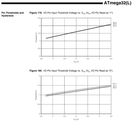
Note that only the CMOS version of the Z80 CPU can be used here. This because only CMOS version, under given condition that are respected in this schematic, has logical levels compatibles with Atmega32A and 74HC00.


NOTES ABOUT THE COMPONENTS:


You can use any Z80 CMOS speed grade, because the lowest is 4MHz.
The 74HC00 can be substituted with a 74HCT00 if you already have one.
The RAM chip TC551001-70 can be substituted with any suitable 64kB RAM (do not use < 64kB RAM).
The USER led (D5 in the schematic) MUST be blue or white just to be sure that V(forward) is >= 3V.


Here is a video that shows a simple basic program that interacts with the "USER led" and "USER key":


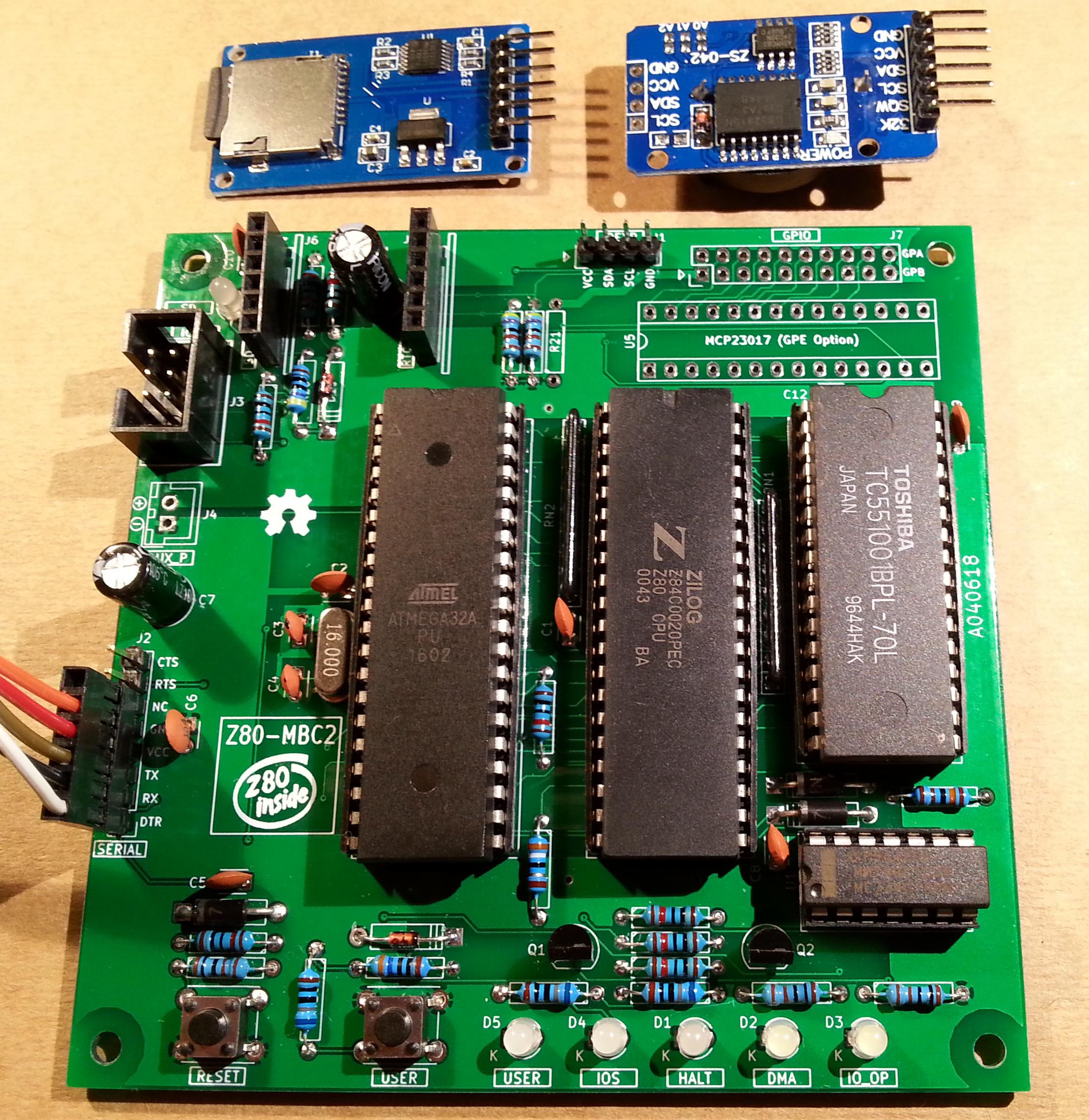
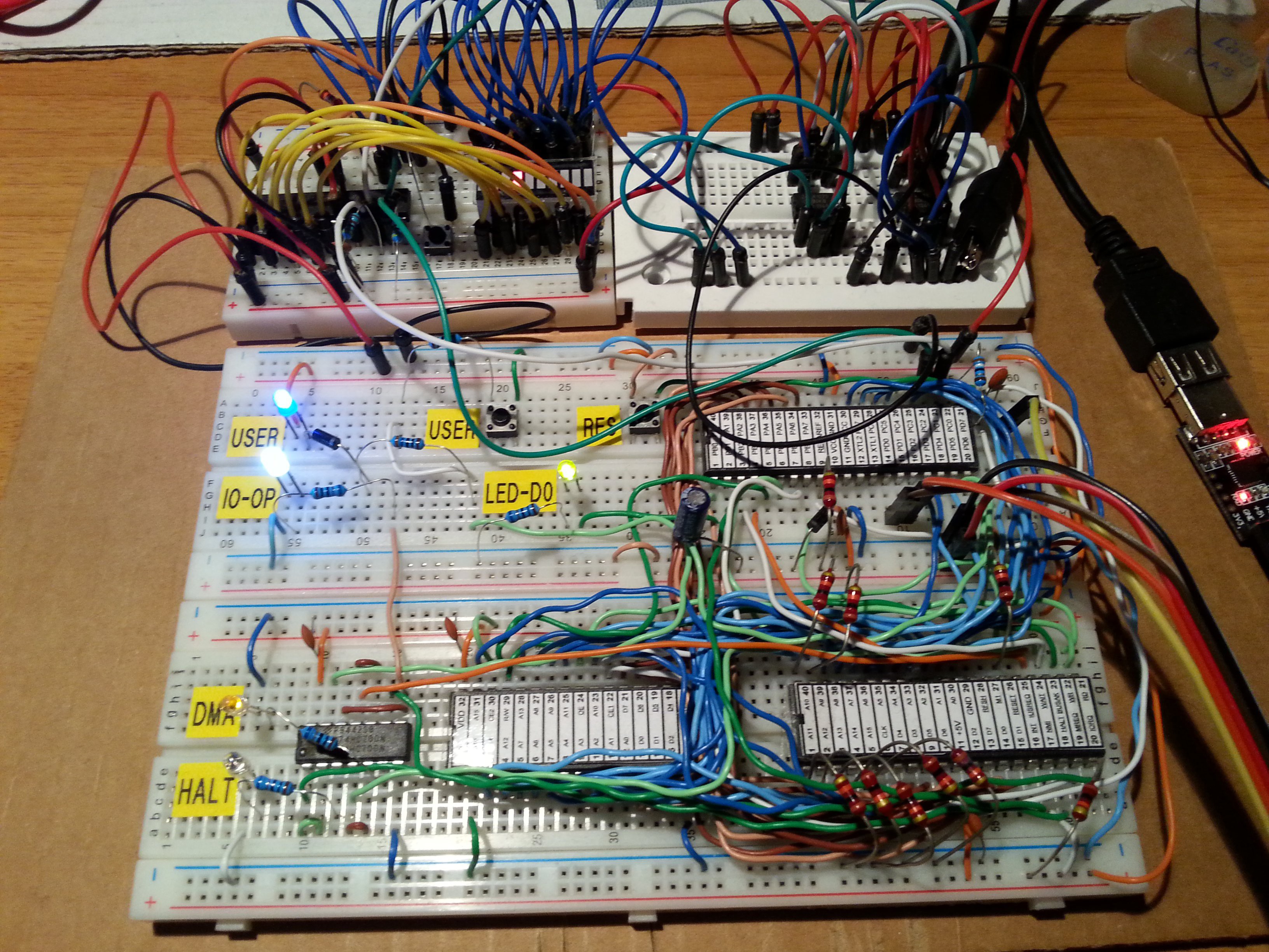
On the breadboard there are others status led: the HALT led turns on if an HALT instruction is been executed and the Z80 CPU is in a Halt state, the DMA led turns on during DMA operations when the Z80 bus is in Hi-Z, the IO_OP led turns on when the Z80 CPU is accessing a I/O virtual device "emulated" by the Atmega32A (as the serial port), the LED_D0 led is the classical "Arduino" led (that one connected to D13 pin on the Arduino Uno) that here is connected with the Arduino D0 pin and is turned on normally as a power on indicator.


The serial port SERIAL-USB (see schematic)...

Read more »

S221116_R050720_Z80.ino

Adds support for 4 drives and others updates. Please see the following repo (created by Al Williams) for new tools, updates and info: https://github.com/wd5gnr/Z80-MBC (by Al Williams)

ino - 165.09 kB - 07/07/2020 at 13:13

Download

S111216.c

TASM Assembler utility.

C Source File - 1.21 kB - 05/15/2018 at 06:05

Download

build.sh

Linux shell script to invoke TASM for WINDOWS (using wine) to assemble Z80 source code and produce a HEX file and a 'C' header file containing the code. Requires TASM 3.2 and wine. See the notes in the script (by Scott).

x-shellscript - 1020.00 bytes - 05/14/2018 at 19:31

Download

optiboot_m32-20mhz.hex

Anyone wishing to overclock the AVR at 20MHz; OptiBoot HEX file for ATmega32/A running at 20MHz (by Scott).

x-hex - 1.31 kB - 05/14/2018 at 18:29

Download

optiboot_m32-8mhz.hex

OptiBoot HEX file for ATmega32/A running at 8MHz (by Scott).

x-hex - 1.31 kB - 05/14/2018 at 18:28

Download

View all 39 files

  • 1 × For the breadboard version see the file "Z80-MBC - BOM.xls" in the Files section
  • 2 × For the PCB version see the file "Z80-MBC PCB version - BOM.xls" in the Files section

  • The Z80-MBC2 is out!

    Just4Fun07/25/2018 at 16:25 0 comments
  • Hardware Fix for the A041116 schematic (USER led and key)

    Just4Fun07/19/2018 at 18:09 0 comments

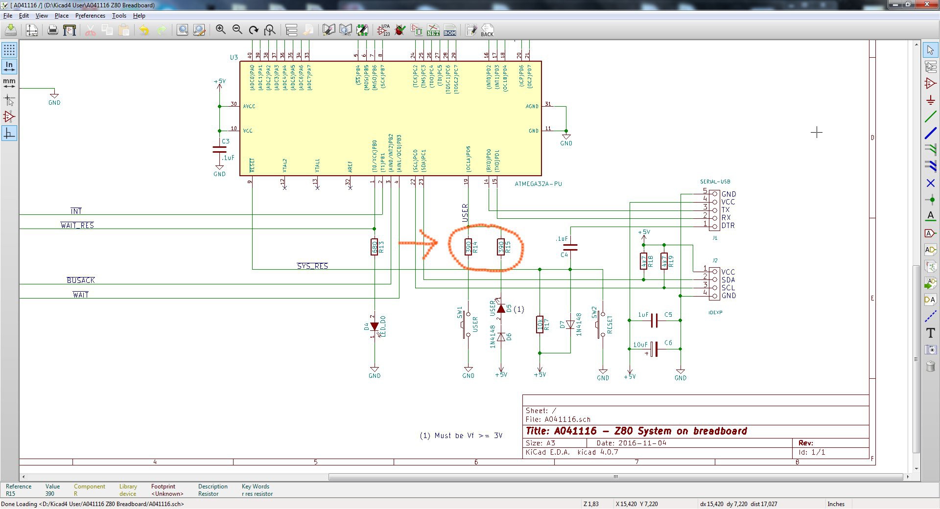
    During some tests on the new Z80-MBC2 I realized that the circuitry of the USER led and key (that is the same used in the Z80-MBC) could cause in some cases an erratic behavior of the USER key (USER key not recognized when pressed).

    The solution is easy, and the fix requires only to change the values of R14 and R15 (see the A041116 schematic) to 390 Ohm (both) as shown:

    Remember that the USER led (D5) must have a forward voltage drop (Vf) of at least 2.7V (e.g. a blue led).

    Please note that this fix is suggested only if you are building a new board or if you are experiencing difficulties with the USER key.

    If you already have a perfect working board there is absolutely no need to apply this fix.

  • Bug fix: the "ghost RTC"

    Just4Fun02/10/2018 at 17:01 0 comments

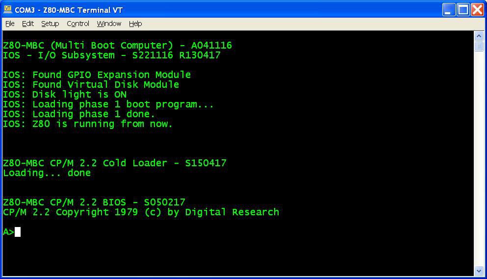
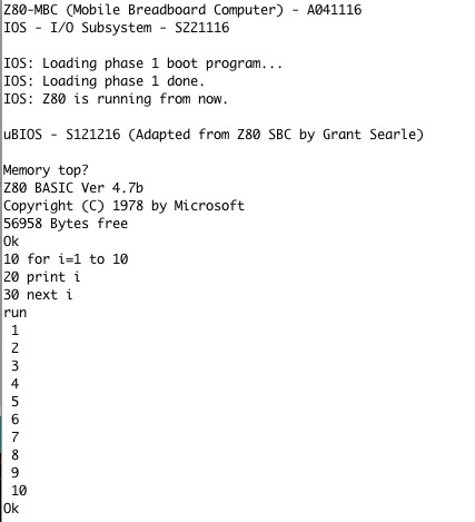
    Reading this Japanese article on a kit sold in Japan to build a Z80-MCB, I realized the presence of a possible bug seeing this two images:

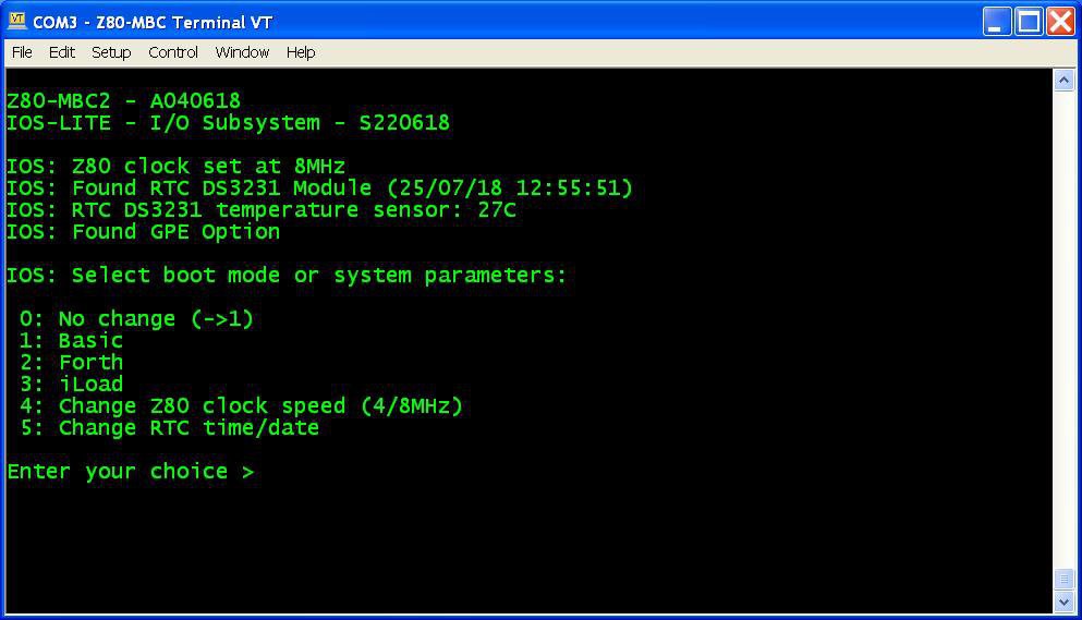
    As you can see, there is a Z80-MCB without any Virtual Disk or RTC attached and in the resulting screenshot the RTC appears present.

    After a quick check I found a little bug in the RTC discovery routine that see a "ghost RTC" when the Virtual Disk is not present.

    So I've uploaded a new "sketch" (S221116_R100218_Z80.ino) that fix the bug.

    Note that if you have the Virtual Disk already installed, there isn't any real need to upgrade.

  • How to make custom Virtual Disk images

    Just4Fun05/29/2017 at 14:29 1 comment

    To do that you need two really powerful tools: Cpmtools to create CP/M disk images and SRecord to manipulate ROM/EPROM images.
    Take in account that the structures of the virtual disk 0 and 1 of the Z80-MBC are different. Disk 0 has the two first tracks reserved for the system image (loaded into RAM by the CP/M loader), instead disk 1 doesn't have this "reservation". This means that the images have a different "structure". More, because disk 0 must have the system image inside the two first tracks, the disk 0 image creation will be different if the OS is CP/M rather than QP/M.
    So to make things easier I've prepared some batch file to simplify the needed operations.
    As for the Assembler and C toolchains you need a Windows host or VM.


    Here all the steps to set up the needed tools:

    1. Create a working directory on your Windows Machine;
    2. Download Cpmtools and unzip in your working directory;
    3. Download last version of SRecord and unzip in your working directory;
    4. Download from the Files section CPMtools-custom.zip and unzip the files into the directory containing the Cpmtool executables (as cpmcp.exe). During the copy overwrite the file DISKDEFS because the new one contains the needed definitions for the Z80-MBC;
    5. Download from the Files section SRecord-custom.zip and unzip the files into the directory containing the SRecord executables (as srec_cat.exe).

    Now you are ready to create your custom image. First create a sub-directory (called e.g. CPM-files) in the cpmtools directory to store all the files to load in the disk image. Check that they fit into the 128kB avaliable space.


    Steps to create a Disk 1 image

    1. Go to the cpmtools directory and with an editor modify/add/delete in the file MakeDisk1.bat the various lines "cpmcp -f z80mbc-d1 %dskfile% CPM-files\xxxxx.yyy 0:xxxxx.yyy" to match the directory in your host (if needed) and all the files to load (xxxxx.yyy);
    2. From the cpmtools directory open the provided DOS command shell and give the following command (I'll use here the name disk1.dsk for the disk image file):
      MAKEDISK1 disk1.dsk
    3. After the execution copy the file disk1.dsk in the SRecord directory;
    4. Go to the SRecord directory, open the provided DOS command shell and give the following command:
      D1TOHEX disk1.dsk
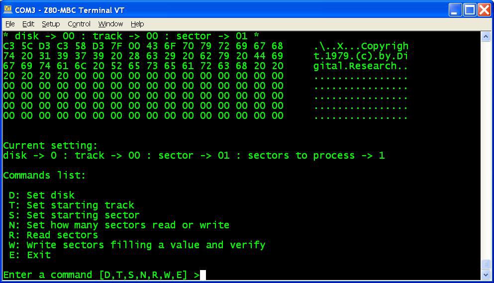
    5. After the execution you will find four files named from disk1_SEG0.hex to disk1_SEG4.hex to upload into the virtual disk with iDisk.


    Steps to create a Disk 0 CP/M image

    1. Go to the cpmtools directory and with an editor modify/add/delete in the file MakeDisk0CPM.bat the various lines "cpmcp -f z80mbc-d0 %dskfile% CPM-files\xxxxx.yyy 0:xxxxx.yyy" to match the directory in your host (if needed) and all the files to load (xxxxx.yyy);
    2. From the cpmtools directory open the provided DOS command shell and give the following command (I'll use here the name disk0CPM.dsk for the disk image file):
      MAKEDISK0CPM disk0CPM.dsk
    3. After the execution copy the file disk0CPM.dsk in the SRecord directory;
    4. Go to the SRecord directory, open the provided DOS command shell and give the following command:
      D0TOHEXCPM disk0CPM.dsk
    5. After the execution you will find four files named from disk0CPM_SEG0.hex to disk0CPM_SEG4.hex to upload into the virtual disk with iDisk.


    Steps to create a Disk 0 QP/M image

    1. Go to the cpmtools directory and with an editor modify/add/delete in the file MakeDisk0QPM.bat the various lines "cpmcp -f z80mbc-d0 %dskfile% CPM-files\xxxxx.yyy 0:xxxxx.yyy" to match the directory in your host (if needed) and all the files to load (xxxxx.yyy);
    2. From the cpmtools directory open the provided DOS command shell and give the following command (I'll use here the name disk0QPM.dsk for the disk image file):
      MAKEDISK0QPM disk0QPM.dsk
    3. After the execution copy the file disk0QPM.dsk in the SRecord directory;
    4. Go to the SRecord directory, open the provided DOS command shell and give the following command:
      D0TOHEXQPM disk0QPM.dsk
    5. After the execution you will find four files named from disk0QPM_SEG0.hex to disk0QPM_SEG4.hex to upload into the virtual disk with iDisk.

    Remember that you...

    Read more »

  • A new OS: QP/M 2.71 and a RTC for timestamping

    Just4Fun05/23/2017 at 15:37 0 comments

    Here is an interesting alternative to CP/M developed by MICROCode Consulting that supports also file timestamping, and it is 100% CP/M 2.2 "compatible".
    MICROCode Consulting has released the original installation files and all the documentation in their site with the "restricted usage" condition, that means free for non-commercial use and for personal use only, so it should be ok for us. Anyway I've sent them a mail about this project.
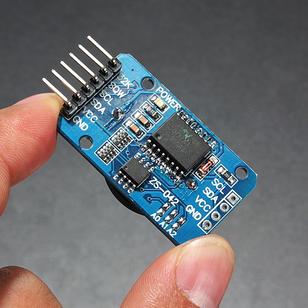
    To enable timestamping you need a DS3231 based RTC module like this one:

    WARNING: these modules can cause battery "explosion"! How to fix it

    This cheap modules have a trickle charging circuit that may cause the "explosion" of the battery if you use a standard CR2032 cell. More, it can damage also a rechargeable LIR2032 cell (see this thread). So the safer thing is "disable" the trickle charging circuit (a CR2032 can last 5/10 years, so there is no practical need to a rechargeable battery, after all...).
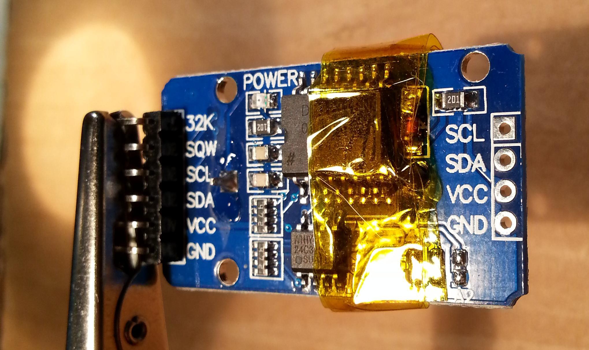
    To avoid any charging current flowing into the battery you can take away the series limiting 200 Ohm resistor (or cut the trace). Alternatively you can take away the red diode, or destroy it (it is in series with the 200 Ohm resistor). In the following photo you can see the module with some Kapton tape (used as thermal barrier) before to desolder the 200 Ohm resistor (on the right marked as 201) with an hot air gun:

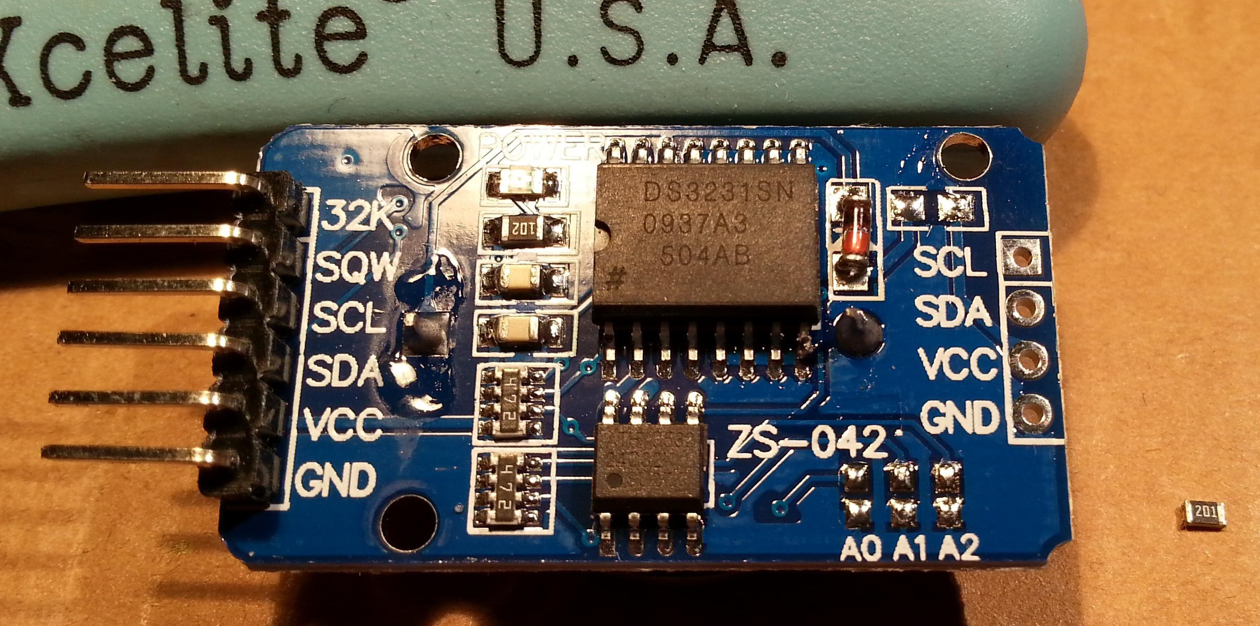
    And here after the desoldering:

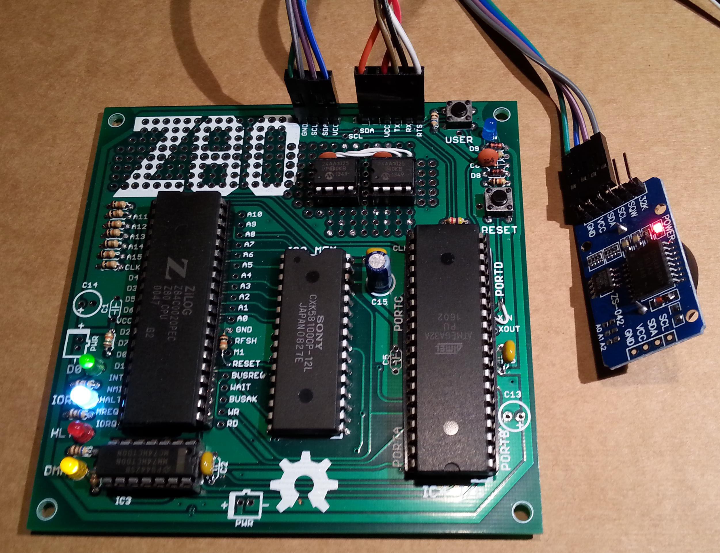
    Now the module it's safe and a CR2032 can be used. To connect it use the SCL/SDA/VCC/GND terminals and connect them at the corresponding pins of the IOEXP/I2C connector of the Z80-MBC (pay attention because the position of the signals is different):

    QP/M quick set up guide

    The setup is quite similar to those used to install CP/M. The Assembler automated toolchain must be already set up and the Virtual Disk Module present.

    Here all the steps:

    1. Connect the DS3231 module (with the CR2032 battery inside);
    2. Update the IOS using the new file S221116_R100218_Z80.ino in the File section;
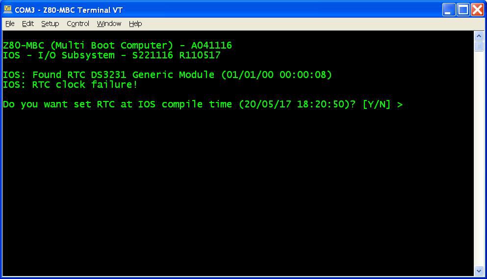
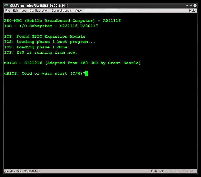
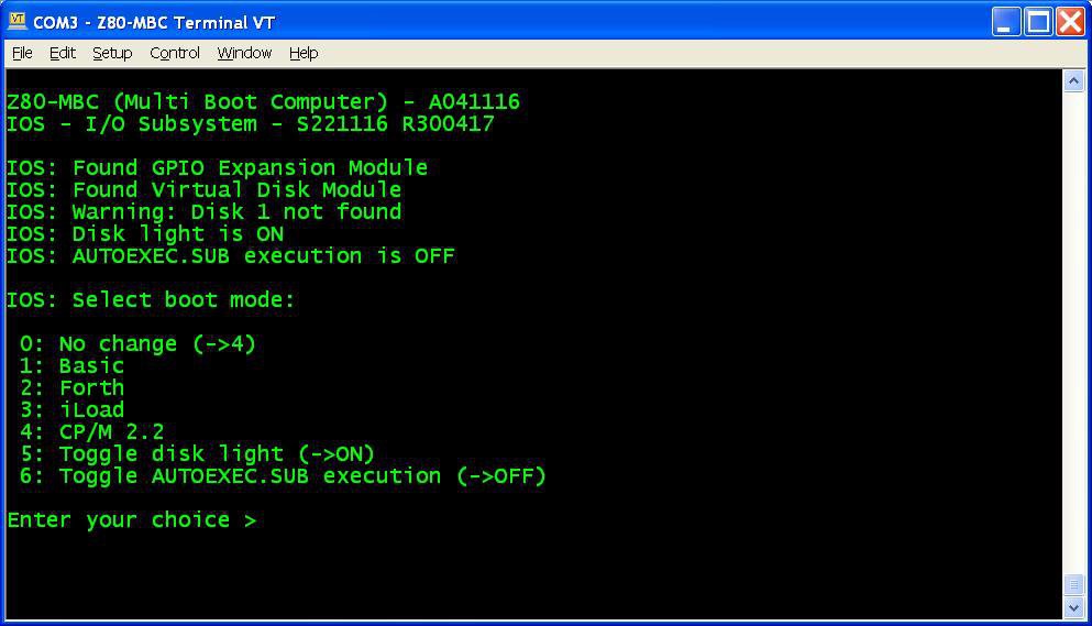
    3. Reboot the Z80-MBC and from a terminal emulator you'll see this:
      Press Y. If you are enough fast you have the RTC set up with the right date/time taken from the sketch compile time (if you are lazy like me you'll find this very handy...). In any case it is possible adjust the date/time manually too from the boot selection menu;
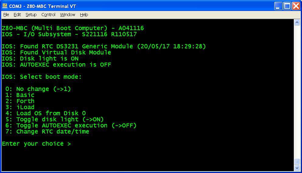
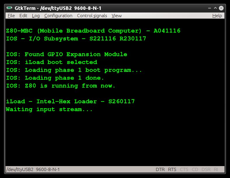
    4. Reboot the Z80-MBC again and select the iLoad boot mode;
    5. From the File section download the file "QPM271_DiskPack.zip", unzip it in the directory used for the Assembler automated toolchain;
    6. Upload the file "iDisk - S250317.hex" to the Z80-MBC using the Dos batch L.BAT (see Assembler automated toolchain) with the command:
      L "iDisk - S250317.hex"
      
    7. When iDisk waits for the input stream, from the Tera Term menu select "File" -> "Send file..." and choice one of the unzipped .hex file from QPM271_DiskPack.zip;
    8. Repeat step 7 for all the four files;
    9. Press the Reset button on the Z80-MBC and enter into the boot selection menu and select 4 to load the OS from disk 0 (and select the disk light ON if not already done, to have an idea of the behavior):

    NOTE: as already noticed, if you experience errors during the serial upload increase the delay after each line from the Tera Term menu (Setup -> Serial port -> Transmit delay -> msec/line). In my VM I set up a 90ms delay. This is due because Arduino serial port doesn't have any handshaking.

    Now you have QP/M 2.71 up and running, but you need further operations to enable the file timestampig (as stated in the QP/M Installation Guide):

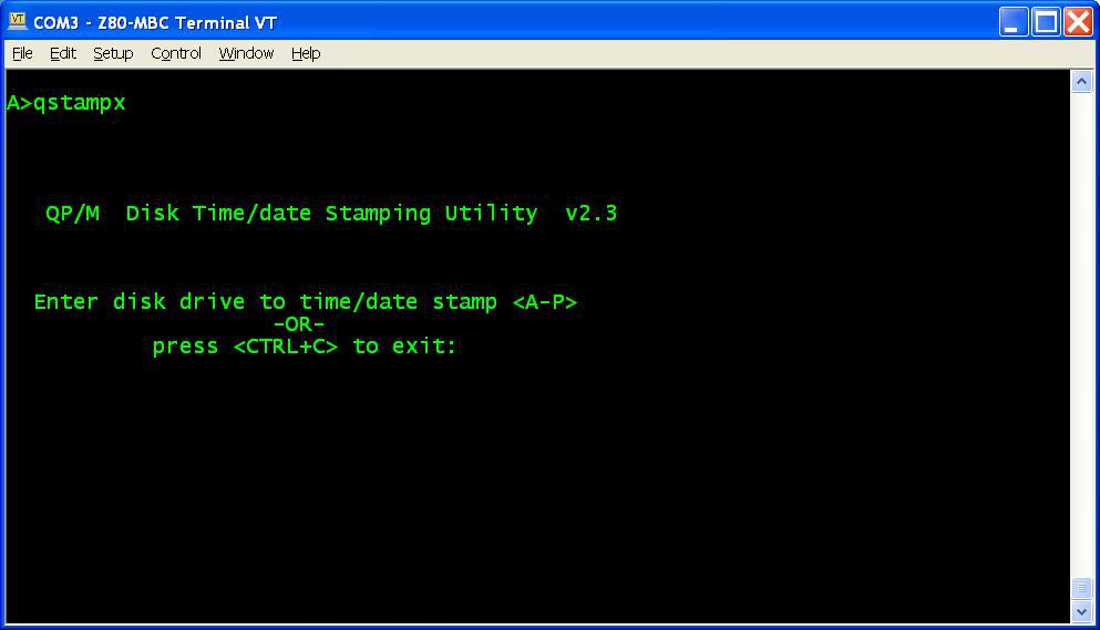
    1. To enable file disk timestamping it is necessary run the utility QSTAMPX from A:
      and do the "disk timestamping" for both A: and B: disks.
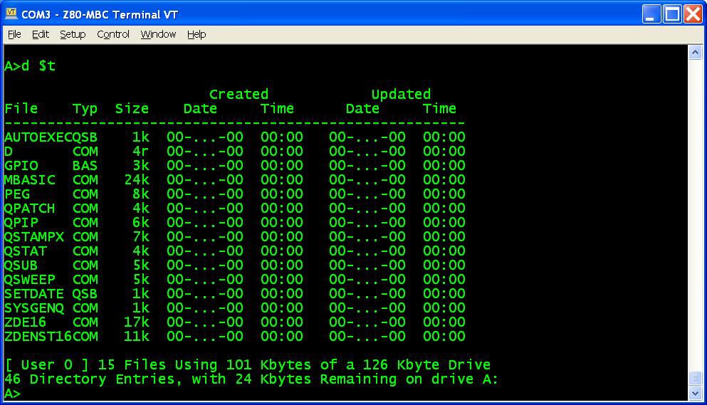
      When done type the command D $T and check that the output is similar to this:
    2. Now to set up a starting date to all files give the command QSUB SETDATE to run a simple batch that I made to do this initialization easily;
    3. Copy the file SETDATE.QSB to drive B: (using the command QPIP B:=SETDATE.QSB) and repeat from B: the same batch (QSUB SETDATE)....
    Read more »

  • AUTOEXEC for CP/M

    Just4Fun05/02/2017 at 16:39 1 comment

    Playing with the Z80-MBC I realized that there was a missing feature: to run a program automatically after the "cold" boot.
    So after some searches I found a way to implement in the BIOS a function similar to AUTOEXEC.BAT for DOS using the CP/M SUBMIT command and a batch file that I called AUTOEXEC.SUB (of course...).
    Editing the AUTOEXEC.SUB file it is possible to run a sequence of commands after the cold boot (as with AUTOEXEC.BAT for DOS), and it is possible enable or disable the execution of the AUTOEXEC batch file from the IOS boot selection menu (but this isn't possible with DOS...).


    AUTOEXEC for CP/M quick set up guide

    You must have CP/M 2.2 already up and running (see CP/M 2.2, iDisk and a new IOS), and you can have also only a "single disk" installed (but I recommend the original dual disk configuration), meaning that only U1 (see the A110417 schematic) is populated. Of course the Assembler automated toolchain must be already set up.


    Here all the steps:

    1. Update the IOS using the new file S221116_R300417_Z80.ino in the File section;
    2. Reboot the Z80-MBC and select the iLoad boot mode;
    3. From the File section download the file CPM22SYS_BIOS_S050217_R300417.hex. This file contains only the new CP/M system image for the system tracks of Disk 0, so the "user files" will be left untouched;
    4. Upload the file "iDisk - S250317.hex" to the Z80-MBC using the Dos batch L.BAT (see CP/M 2.2, iDisk and a new IOS) with the command:
      L "iDisk - S250317.hex"
    5. When iDisk waits for the input stream:from the Tera Term menu select "File" -> "Send file..." and choice CPM22SYS_BIOS_S050217_R300417.hex. After the upload iDisk will show a summary, at this point press W to proceed and confirm your choice (as done for the CP/M 2.2 installation described in CP/M 2.2, iDisk and a new IOS). Wait until the write and verify phase is completed.
    6. Press the Reset button on the Z80-MBC and enter into the boot selection menu and select 4 for CP/M loader.


    All done!


    NOTE: as already noticed, if you experience errors during the serial upload increase the delay after each line from the Tera Term menu (Setup -> Serial port -> Transmit delay -> msec/line). In my VM I set up a 90ms delay. This is due because Arduino serial port doesn't have any handshaking.


    How use it

    To create or edit AUTOEXEC.SUB from drive A, you can use the ED command or an other editor like the Turbo Pascal editor. In this case remember to terminate the file with a CR, or "strange" things will occur when executing the SUBMIT AUTOEXEC command.
    You can test the execution giving the command SUBMIT AUTOEXEC from drive A (you can omit the extension .SUB inside the SUBMIT command).
    To enable the AUTOEXEC execution after the cold boot change the corresponding state to ON from the usual IOS boot selection menu.
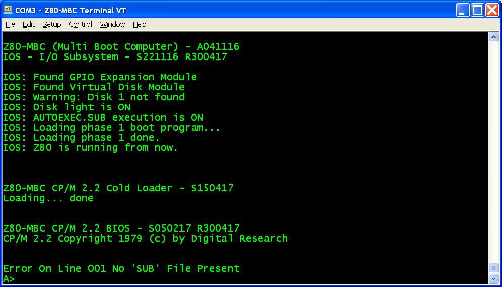
    If the AUTOEXEC is enabled but the AUTOEXEC.SUB file doesn't exist in the drive A, an error will be displayed:


    New "disk packs"

    I've updated both "disk packs" in the files CPM22_DualDiskPack_v2.zip and CPM22_SingleDiskPack_v2.zip with the new BIOS in the system tracks. So if you are installing them for the first time or you need for any reason to reload them, the new BIOS will be installed. I've added an example of AUTOEXEC.SUB too.


    How it works

    The "trick" used was to inject the string "SUBMIT AUTOEXEC" into the CCP (the Command Processor of CP/M) input buffer. The BIOS after the cold boot checks if the AUTOEXEC flag is set in the IOS, and in this case makes the injection. When the CCP starts after the cold boot, it runs this injected command.

    In this video there is an in depth explanation for a "legacy" Altair 8800 clone.

    The CP/M 2.2 and the new BIOS sources are in the file "CPM22 BIOS - S050217 R300417.zip" in the File section.

  • CP/M 2.2, iDisk and a new IOS

    Just4Fun04/20/2017 at 20:36 14 comments

    CP/M 2.2 quick set up guide

    The set up is very simple. I've done an utility (iDisk) to simplify all the needed operations. Of course the Virtual Disk Module must be present, but you can have also only a "single disk" installed (but I recommend the original dual disk configuration), meaning that only U1 (see the A110417.pdf schematic) is populated.
    The Assembler automated toolchain must be already set up.


    Here all the steps:

    1. Update the IOS using the new file S221116_R130417_Z80.ino (or a newer version if present) in the File section;
    2. Reboot the Z80-MBC and select the iLoad boot mode (if not already selected);
    3. From the File section download the file "iDisk - S250317.hex" and copy it into your PC in the directory used for the Assembler automated toolchain . (Do not use the source file "iDisk - S250317.c" because it requires a special compiling option);
    4. From the File section download the file "CPM22_DualDiskPack.zip" and unzip it (for a single disk configuration download the file "CPM22_SingleDiskPack.zip"). Each disk image is divided into four .hex files called "segment" (32kB each) that are named accordingly (e.g. D0XXX_SEG1.hex means the segment 1 of disk 0);
    5. Upload the file "iDisk - S250317.hex" to the Z80-MBC using the Dos batch L.BAT (see Assembler automated toolchain) with the command:
      L "iDisk - S250317.hex"
          
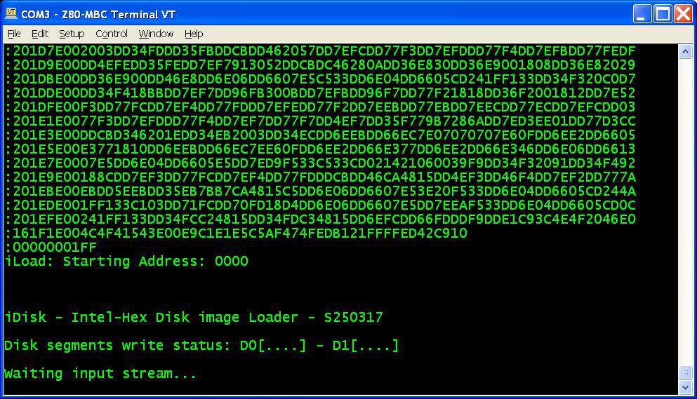
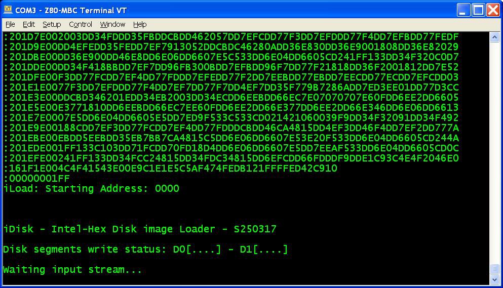
    6. When iDisk waits for the input stream:
      from the Tera Term menu select "File" -> "Send file..." and choice one of the unzipped .hex file from CPM22_DualDiskPack.zip (or CPM22_SingleDiskPack.zip for a single disk configuration). After the upload iDisk will show a summary:
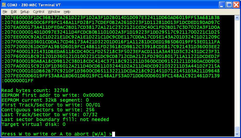
      at this point press W to proceed and confirm your choice.
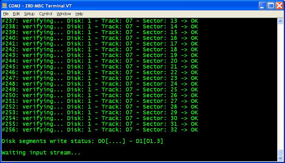
      You don't have to follow any order in the "segments" upload sequence, iDisk will know how to do. To know before each upload what "segments" have been already written into the disks just see the "Disk segment write status":
      in the photo the segments 0, 1 and 3 of Disk 1 have been already successfully written, so you can choose any of the remaining;
    7. Repeat step 6 for all the eight (or four for the single disk pack) "segment" files;
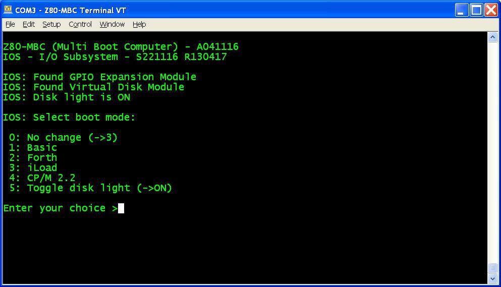
    8. Press the Reset button on the Z80-MBC and enter into the boot selection menu:
      select 4 for the CP/M loader (and select the disk light ON if not already done, to have an idea of the behavior).
    All done!


    NOTE: if you experience errors during the serial upload increase the delay after each line from the Tera Term menu (Setup -> Serial port -> Transmit delay -> msec/line). In my VM I set up a 90ms delay. This is due because Arduino serial port doesn't have any handshaking.

    Disk speed

    The Virtual Disk Module is based on simple EEPROMs using a 200KHz I2C serial bus. Of course do not expect the same speed of an hard disk with a DMA controller!
    The speed probably is like using the floppy drive of those days...

    Single disk configuration

    You can have also only a "single disk" installed (but I recommend the original dual disk configuration), meaning that only U1 (see the A110417.pdf schematic) is populated.

    In this case you have about 120kB free, because the first two tracks of Disk 0 are reserved for the system image (Disk 1 doesn't have the system image, so all the 32 tracks are used for the file system).

    Because the BIOS is the same and is configured for a dual disk system, if you try to select the "B:" drive you'll get a "BAD SECTOR" error.

    Disk pack contents

    In the disk 0 image there are the various external CP/M commands, the Basic interpreter, the CP/M Assembler and the Macro Assembler.
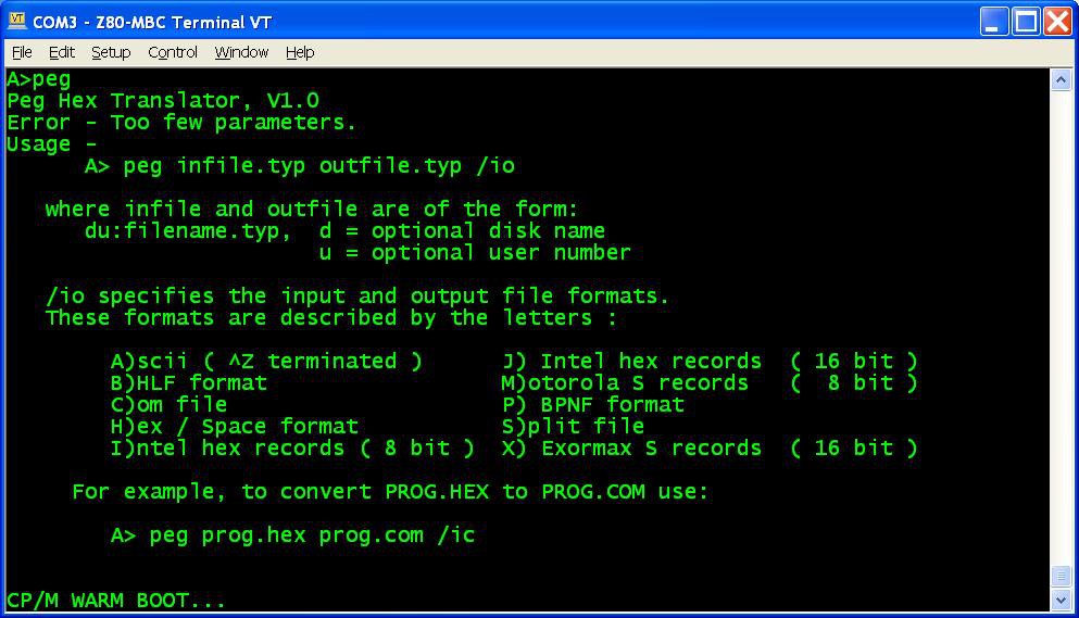
    I've added also D, an alternative DIR command, and PEG, a bin to hex converter (and vice-versa) to exchange files:

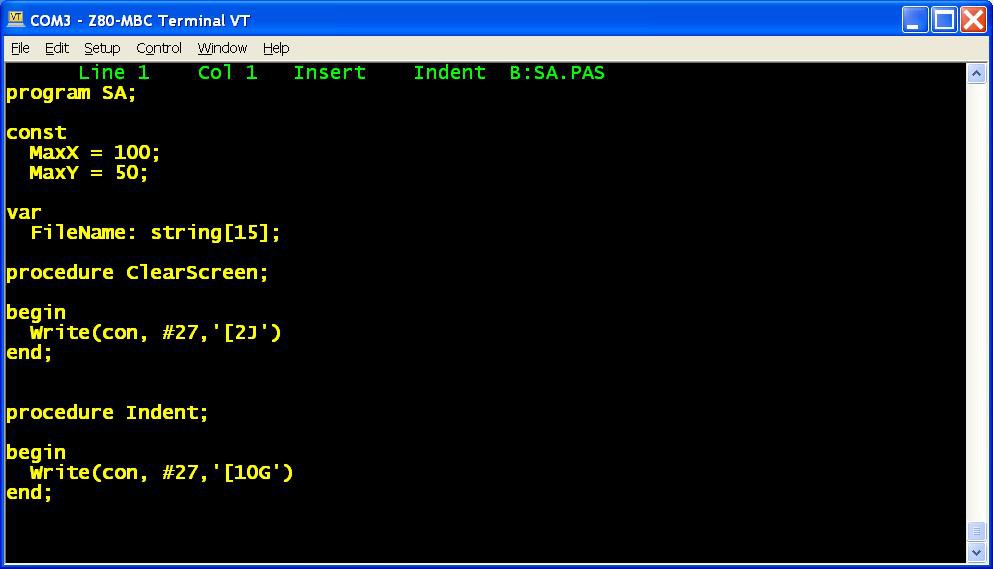
    In the disk 1 image there is the complete Turbo Pascal compiler v3.01A with a sample program (SA.PAS):

    In the "single disk pack" the CP/M Assembler and the Macro Assembler are missing, and the Turbo Pascal is without the installing executable (not a big issue anyway) and without the sample program.
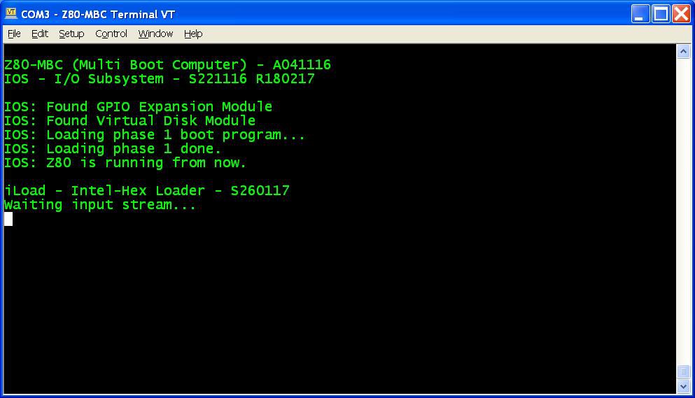
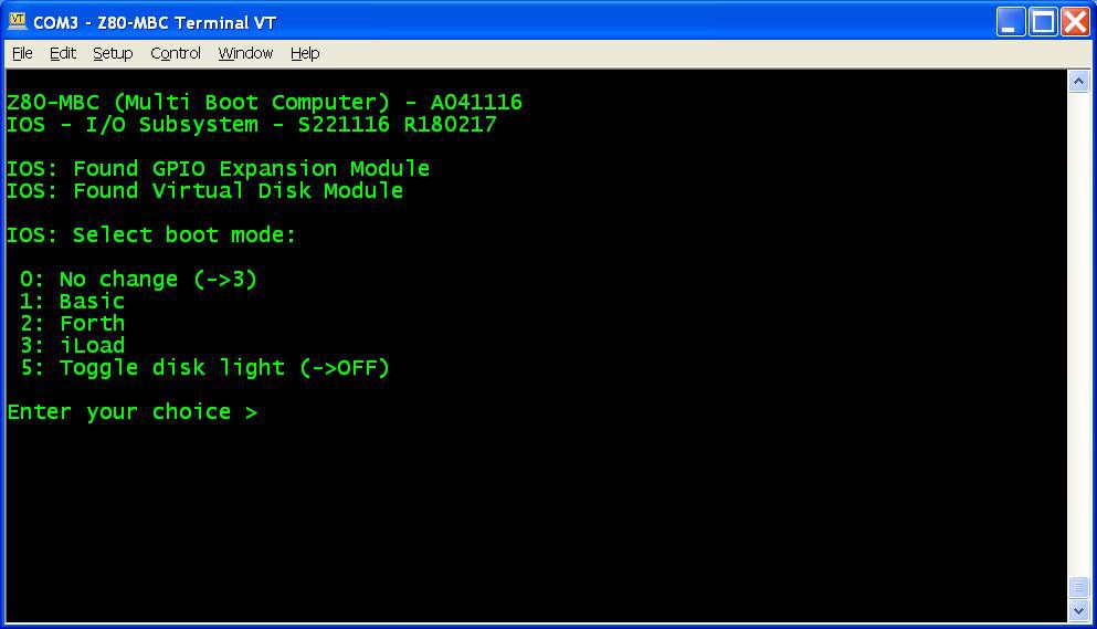
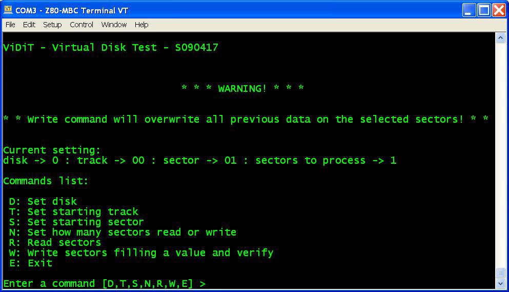
    In a next Log I'll explain how create custom...

    Read more »

  • Virtual Disk Module, a new IOS and ViDiT

    Just4Fun04/13/2017 at 19:37 3 comments

    It's time for a new "module", the Virtual Disk Module! In the photo is that one on the right, near the previous GPIO module.

    In the File section is possible see the simple schematic A110417.pdf with two I2C EEPROM 24LC1025.

    With this module it is possible to emulate two disks of 128kB each (probably like the floppy disk drives of those years).

    Each disk is divided into 32 tracks of 32 sectors. Each sector is 128 bytes long.

    Of course to manage this new HW there is a new release of IOS. The new file S221116_R180217_Z80.ino is in the File section.

    This new IOS checks if the module is present and prints a message if found:

    There is also a new item in the boot selection menu if the virtual disk is found, to use the User led as a disk activity led:

    I suggest to activate this option to have an idea of the behavior.


    ViDiT

    In the File section I've added a simple test program (file "ViDiT - S090417.c") to check the virtual disk. Of course you need to compile it with the C "toolchain":


    About I2C speed

    With this IOS the I2C speed is 200KHz. Note that if you are using a 16MHz external quartz to clock the Atmega32 the I2C speed will be 400kHz. In this case I suggest to lower the two 4k7 pull-up resistors (on SDA and SCL signals) to about 2k2.


    The next Log will bring the CP/M 2.2 up and running...

  • Forth language, new multi-boot selection and a new name

    Just4Fun02/17/2017 at 21:33 4 comments

    Forth


    Thanks to Bill Westfield now we have a new language for the Z80-MBC, the fig-FORTH v1.3 (here the link to the Bill GitHub repository with the source he adapted for the TASM assembler with the needed modifications for the Z80-MBC).

    The acronym "fig" stands for "Forth Interest Group", that was a world-wide non-profit organization (now dissolved) for the promotion of the Forth computer language.
    I've just started to play with this thing, and I must say that it is not the most friendly language I've seen... anyway it is an interesting different approach.

    To enable Forth just upload the new IOS release S221116_R120217_Z80.ino in the Files section, and select the Forth language from the new multi-boot menu (see next paragraph).

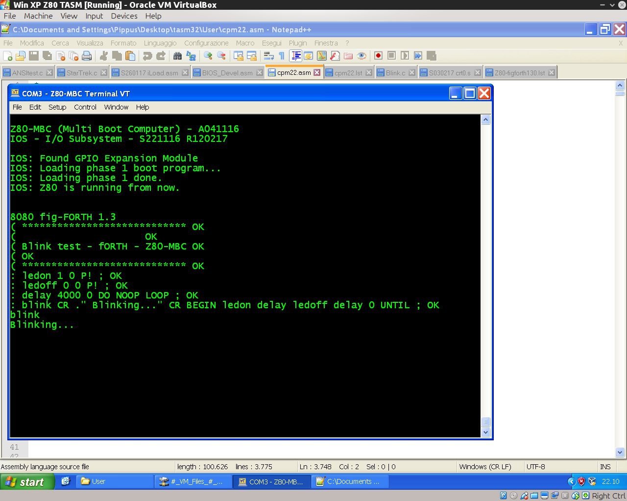
    Here it is a "blink" demo program:

    ( ****************************
    (                     
    ( Blink test - Forth - Z80-MBC
    (
    ( ****************************
    : ledon 1 0 P! ;
    : ledoff 0 0 P! ;
    : delay 4000 0 DO NOOP LOOP ;
    : blink CR ." Blinking..." CR BEGIN ledon delay ledoff delay 0 UNTIL ;

    To execute give the command "blink":


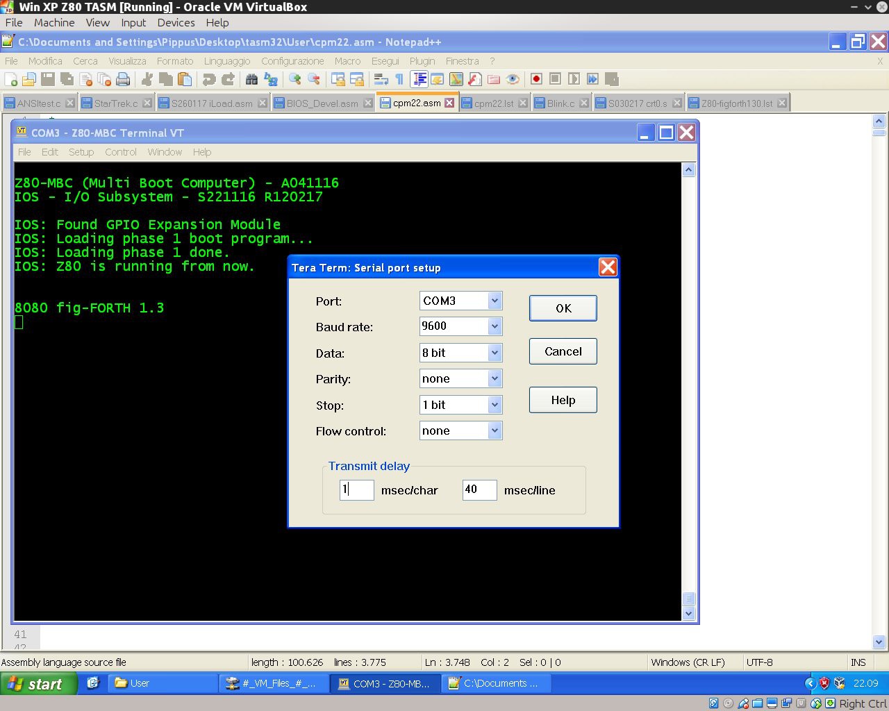
    If you are using Tera Term to send a text file to load a forth source, remember to set up a delay of 1ms for each character (serial port managed by the Arduino bootlader doesn't have any handshaking, so for now this is required to handle the serial stream without errors when sending a text file using a terminal emulator):


    New multi-boot selection


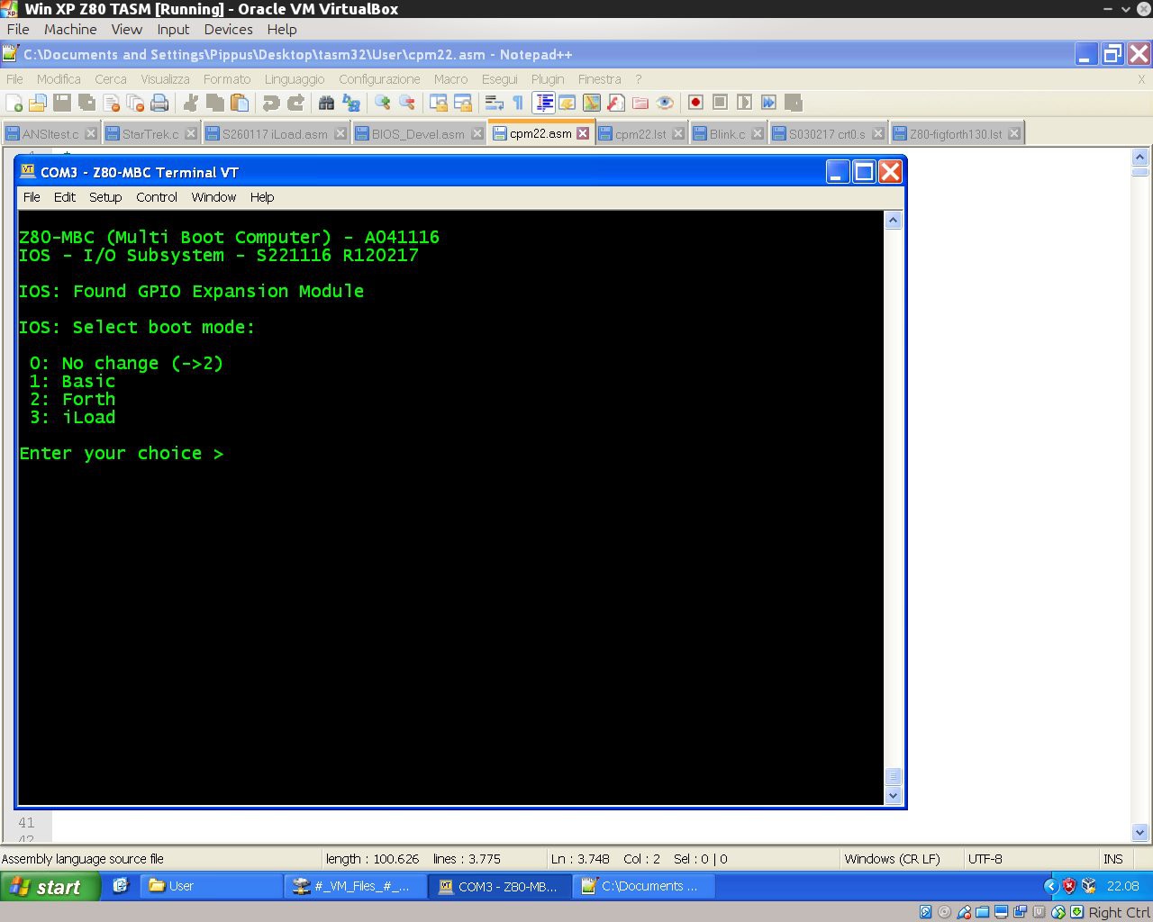
    Now pressing the User key after a reset brings to a new menu to chose the preferred boot mode. During this phase the LED-D0 will blink until you choose the boot mode:


    New name


    As you can see from the previous photos, from this release the MBC acronym changes to "Multi Boot Computer"...

  • An automated C language toolchain

    Just4Fun02/09/2017 at 21:26 0 comments

    Here how set up a toolchain to program the Z80-MBC using the C language. It is based on SDCC (Small Device C Compiler) and uses the same "process" of the previous Assembler toolchain.
    In the following it is assumed the the Assembler toolchain is already set up in a Windows host as described in in the Log: New iLoad boot mode and an automated Assembler toolchain.
    So only the SDCC relevant part is explained here.


    Here it is a short video with the toolchain in action:

    What you need to do:

    1. Create a working directory (or use the previous one) where to store the C sources and the two batch files (C.BAT and L.BAT) in the C_batch.zip file from the File section (if you are using the same assembler working directory overwrite the previous L.BAT);
    2. With a text editor search the line:
      "C:\Program Files\teraterm\ttermpro.exe" /c=3 /BAUD=9600 /w="Z80-MBC Terminal" /m=LoadZ80.ttl
      inside C.BAT and L.BAT and verify that both the path and the COM number (/c=3 means COM3) meet your system;
    3. Download and install SDDC from here;
    4. Download the file S030217_crt0.s from the Files section in the working directory;
    5. Open the DOS command line and give the command: "sdasz80 -o S030217_crt0.s".
      Then rename the generated S030217_crt0.rel as crt0.rel. Copy it in the SDCC directory "C:\Program Files\SDCC\lib\z80" (may be a bit different in your system) overwriting the old one.

    All done!

    As usual close Tera Term before every new upload.

    To check if it is all ok, download from the File section the file C_demo.zip and unzip it in the working directory.
    From the DOS command line give the command: "C Blink.c" to check if all the toolchain works as in the video.
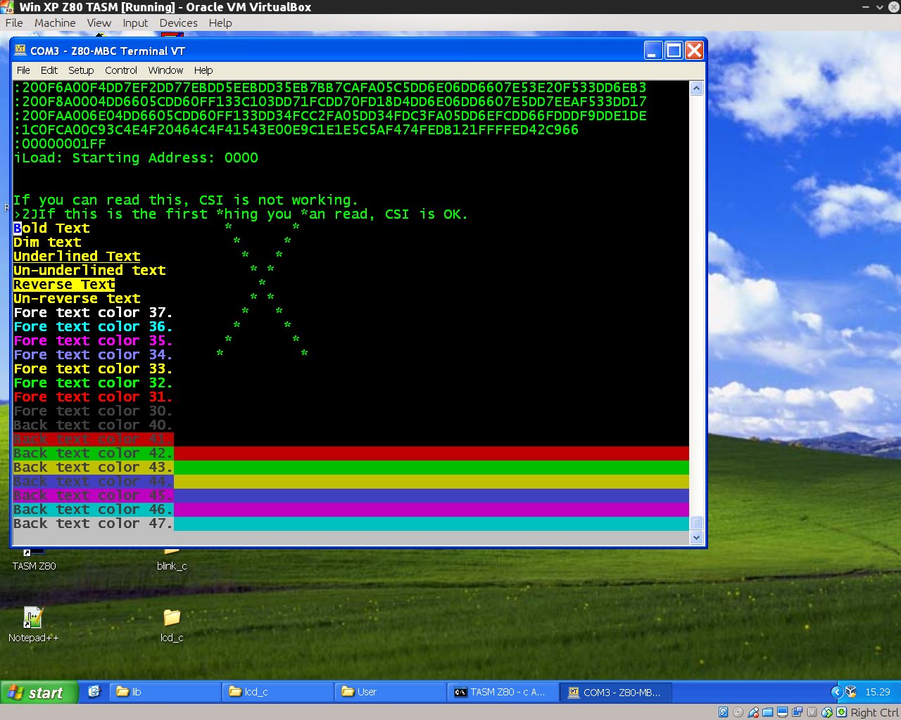
    Try also the other demo ANSItest.c (taken from here) to check the ANSI capabilities of a different terminal emulator or a physical terminal:

    About SDCC

    I'm pretty new to SDCC. The SDCC documentation is 8051 "focused", so the given examples can be misleading if used with an other processor in mind.
    When "porting" SDCC to a target HW, there are 3 things to prepare:

    • customize the crt0.rel file that contains the initialization code for the target system;
    • add to the library the function putchar(char c) to send output to the console;
    • add to the library the function getchar() to read from the keyboard.

    I found the documentation quite missing about how to modify for a custom system.
    In particular in the provided crt0.s example there isn't a needed global declaration of three variables (l__INITIALIZER, s__INITIALIZED and s__INITIALIZER). Without this declaration the code will not compile.
    And to make this customization you need to know how the provided assembler works, but the assembler manual is not provided. So you must find it googling...
    If you are used to the Arduino IDE, read carefully the SDCC manual. This C compiler is a lot more "rude" about types and syntax... (as C standard is...).

    Last minute update

    Just found the assembler and linker documentation here!

View all 14 project logs

  • 1
    Quick instructions intro:

    All the detailed instructions are provided in the "DETAILS" section and in every "LOG".

    Because this project has grown a lot on the way (more than I've supposed at the beginning...) here you can find a short and simple build guide without "navigate" into all the various "LOGs".

    This short guide is referred to the current (at present date 31 August 2017) last "level" of development as described in "A new OS: QP/M 2.71 and a RTC for timestamping".

  • 2
    Add the Atmega32 support in your Arduino IDE:

    The standard distribution of Arduino IDE doesn't have the Atmega32 "core" support files.

    You need to add them from here.

  • 3
    Flash the Atmega32:

    First of all you need to flash the Arduino bootloader into the Atmega32.

    To do this there are a lot of ways. I use a cheap USBASP programmer that you can find "around" for less than 2$.

    Remember to select from Arduino IDE the "Atmega32 8MHz Internal" clock option before flashing the bootloader!!!

View all 6 instructions

Enjoy this project?

Share

Discussions

WestfW wrote 01/30/2017 at 08:53 point

Hmm.  it occurs to me that for old CPUs that have DMA based on "I release the bus!" mechanisms, you could essentially simplify the interface even further (though probably not get the chip count any lower.)  A "mailbox" of shared memory, plus "ATTN", BUSREQ, BUSACK, and RESET, and that's it.  The Z80 (or whatever) would put stuff at a known location and signal ATTN to the AVR, which would then take the bus, read and re-write the shared memory, and give it back.  At poweron, the AVR could put the bootstrap in low memory instead.
I guess the problem is that while you'd still be running on an actual Z80, it would rapidly become non-retro-like WRT its IO...

  Are you sure? yes | no

Just4Fun wrote 01/31/2017 at 07:21 point

Interesting approach... virtually HW independent...

A problem in this case would be that the various CMOS SRAM seem to have strictly TTL outputs (at least datasheets says so...), so readings SRAM directly from an AVR would be possible only using an analog read for each pin and reassembling the byte... possible (in fact the data bus pins are also analog pins... it is not a coincidence...) but time consuming... so I left this way as last chance.

  Are you sure? yes | no

WestfW wrote 01/31/2017 at 09:40 point

Hmm.  The RAM Voh specs are a little annoying, aren't they?  Since the technology is CMOS, I *suspect* the low guaranteed output voltage is a current drive issue, and won't come into play as long a everything that's connected is also CMOS (and not requiring any drive current to speak up.)  In any case, since I'm still waiting for my Z80s, I've been playing with just the AVR and memory, including writing a little "memory test" utility that writes AND READS the memory from the AVR.  It seems to work fine (even though my memory chip also says 2.4v min output.  And the scope shows a nice and solid 5V output.  (you spend a lot of time poking around with a scope if you forget that you have to read PINx rather than PORTx.  Sigh.  The test program pretty much lets you step through individual accesses so you CAN poke around, as well as doing the full speed memory test.)

Single Step Memory Read from 7
Requesting DMA. DDR = 00 f3 fc fc.  PORT = 8a 72 1a 21
Control signal. DDR = 00 f3 fc fc.  PORT = 8a 72 1a a1
Bus Direction. DDR = 00 f3 fc fc.  PORT = 8a 72 1e 21
MREQ_ low   . DDR = 00 f3 fc fc.  PORT = 8a 32 1e 23
RD_ low     . DDR = 00 f3 fc fc.  PORT = f8 12 1e a3
RD_ high    . DDR = 00 f3 fc fc.  PORT = f8 32 1e 23
MREQ_ high  . DDR = 00 f3 fc fc.  PORT = f8 72 1e a3
Data read: f8

https://github.com/WestfW/4chipZ80 if you'd like to play with it.  I *think* it should work with or without the Z80 in-circuit...

  Are you sure? yes | no

Just4Fun wrote 01/31/2017 at 10:16 point

Ops... I've realized only now "Who" you are... :-)

  Are you sure? yes | no

K.C. Lee wrote 01/31/2017 at 10:40 point

I suspect the TTL compatible VOH (min) is left over from the old days for old TTL loads.  Chances are that it would go to full rail for CMOS high impedance only loads.

CMOS input threshold is actually targeted to be half rail.  All the AC timings are usually specified that way. However this parameter is dependent on the input MOSFET P and N types to be identical.  They also want to have enough guard band to make sure that the input stage doesn't have shoot through.

Unfortunately can't depend on the being full CMOS compatible for a proper paper design even though it would likely work for most parts not under extreme conditions.

  Are you sure? yes | no

WestfW wrote 02/01/2017 at 00:48 point

Hmm.  Even the CMOS Z84C00xxx chips have the same 2.4V Voh spec.  Perhaps we're just lucky.  I never would have noticed; is there some famous example of CMOS SRAM *not* working with modern CMOS processors?

  Are you sure? yes | no

Just4Fun wrote 02/01/2017 at 05:27 point

In the Z80 CMOS datasheet there is the Voh2 parameter valid if load is not greater than 250uA. In this case Voh2 is higher than 2.4V...

See page 30 (of the file) here: http://www.mouser.com/ds/2/450/ps0178-19386.pdf

Instead in the various CMOS SRAM datasheet nothing is said for "low" load... :-(

  Are you sure? yes | no

K.C. Lee wrote 02/01/2017 at 10:08 point

You can find them if you know what to look for (and what to do with it).  

There are IBIS model for simulation which are essentially voltage vs current curves data for I/O pads.  These are what people typically use for signal integrity simulation.

https://www.idt.com/products/memory-logic/srams/asynchronous-srams/71256sa-50v-32k-x-8-asynchronous-static-ram  under Software & Tools

  Are you sure? yes | no

K.C. Lee wrote 02/01/2017 at 10:24 point

FYI: The typical VIH is actually very similar to TTL at 5V.  It is however not part of the guaranteed specs.


  Are you sure? yes | no

Just4Fun wrote 02/02/2017 at 07:43 point

Interesting... I have not ever thought about using those simulation models...

  Are you sure? yes | no

Just4Fun wrote 01/28/2017 at 19:37 point

Hi all, a new update is coming... Stay tuned...

Screen_8

  Are you sure? yes | no

john wrote 01/28/2017 at 14:37 point

Just finished my build of this - ended up with ATMEGA32 clocked at 16 MHz so Z80 is running at 8MHz.  Great project and was a lot of fun to build.  


  Are you sure? yes | no

Just4Fun wrote 01/28/2017 at 19:35 point

Thanks! Great built... :-)

  Are you sure? yes | no

Peabody1929 wrote 01/28/2017 at 00:06 point

Outstanding project!  I am going to build one.  I ordered some faster parts: 15ns 64Kx8 CMOS SRAM and 20MHz CMOS Z80.  This could be a damn fast Z80 system.  Thoughts on high performance?

  Are you sure? yes | no

Just4Fun wrote 01/28/2017 at 11:34 point

Thanks!. The FW on Atmega "should work" at those speed "virtually" without modifications. Of course I haven't done any test @ 20MHz... so let me know....

  Are you sure? yes | no

villaromba wrote 01/25/2017 at 16:22 point

Hi, I have a minipro TL866A eprom burner which can handle the ATMega32A. Can I just use your .ino file, program the IC  and then plug into the board and go or do I need a bootloader first? thnx

  Are you sure? yes | no

john wrote 01/25/2017 at 18:40 point

Once you compile the code in the Arduino environment, there will be a .hex file (somewhere in your Arduino folder - can't remember where) that you can use with the TL866A.  I believe in that same folder, there is a version that has the bootloader included as well for the device type you selected in the Arduino environment.  Just make sure to get the fuse bits right, and to disable JTAG or your PortC pins won't work...

  Are you sure? yes | no

Just4Fun wrote 01/26/2017 at 10:08 point

Hi, 

in the Arduino forum someone posted a software to use the TL866 with the Arduino IDE as programmer: https://forum.arduino.cc/index.php?topic=387390.0

It seems that you can upload the .ino directly (no bootloader) with that, and the "burn bootloader" option seems not to work.

So try to give a look....

About the Arduino bootloader, you can upload the .ino (I mean after the compilation, so is an .hex file) without the bootloader too. In this way you need to re-use your programmer for every upload (when/if needed).

  Are you sure? yes | no

Just4Fun wrote 01/21/2017 at 18:17 point

Hi all, something new is coming... Stay tuned...


  Are you sure? yes | no

villaromba wrote 01/21/2017 at 14:39 point

Sorry, sorted out please ignore previous comment !!!!

  Are you sure? yes | no

villaromba wrote 01/21/2017 at 14:34 point

Great project .. I thought before I build the hardware that I would get an Eprom programmed so went through the build cycles - all to the video and all went OK, just a question at the BUILDROM.cmd stage - I get the same options as you - so selected SMB but options that then come up  are different - I get acia, acia_vfd, SIO, SIO_vfd, SIO_vfd_8in ..... I selected SIO but do you think this will be a problem (I didn't get the std that you selected). Thanks for your advice

  Are you sure? yes | no

WestfW wrote 01/18/2017 at 12:35 point

Starting to look relatively real!

Three mistakes so far: two missing pull-x resistors, and a signal trace that collided with a power trace :-(   Nothing too difficult to repair, though!  Still waiting for chips (and it turns out I hadn't ordered them when I thought I had...)   I also bugged Atmel for some samples :-)

  Are you sure? yes | no

Just4Fun wrote 01/18/2017 at 12:54 point
Hi, I've seen that you added a couple of power connectors... good idea...
On the back side (your previous photo) it seems to be some SMD capacitors on it. Do you have added more bypass caps?

  Are you sure? yes | no

WestfW wrote 01/18/2017 at 23:38 point

Yeah. For personal/hobbyist PCBs, I like to put SMT bypass caps on the back of the board (where they usually fit pretty easily) as well as TH caps on the front. That way you can populate with whichever you happen to have on-hand (if you're like me, at some point you bought a "near infinite supply" of some type of bypass cap...) It doesn't hurt that this also means you can do "extra" and "multiple value" caps "if needed."

  Are you sure? yes | no

WestfW wrote 01/27/2017 at 03:32 point

Meh.  My ATmega32s arrived, and I found another bug.  Rx&Tx swapped :-(  I would have thought I would have noticed that!  Also, apparently I don't have any 74HC00s.  I have some in SMT.  I have some 4011s.  I have 74hc30s.  But no DIP 00s that I can find (Now sorting through piles of stuff.  Sigh.)
On the bright side, after spending a day debugging a mis-spelling of "AVR_FREQ" to build a custom bootloader, I now have the AVR mounted on the board and accepting sketch uploads.

  Are you sure? yes | no

Just4Fun wrote 01/27/2017 at 07:42 point

Hi, just for curiosity.... why do you need a custom bootloader?

BTW: Next thing will be a "developer boot mode" and an Assembler "toolchain"...

  Are you sure? yes | no

WestfW wrote 01/28/2017 at 03:00 point

I made the bootloader startup blink happen on your "User" LED.  I'm very familiar with the bootloader, and it should have taken mere seconds.  But it didn't :-(
(using the "Mighty" Core, connect to the bootloaders directory and use "make atmega32 AVR_FREQ=8000000L LED=D5 BAUD_RATE=38400" before you use the "burn bootloader" command in the Arduino IDE.)

ZDDT?  I was going to work on adding some big I2C EEPROMs for "files."  A 1Mbit EEPROM is "about" the size of a floppy "from those days."

  Are you sure? yes | no

WestfW wrote 02/02/2017 at 04:12 point

Woot!  Working.  (without the missing pull-resistors, which may explain some occasional weird behavior...)


  Are you sure? yes | no

Just4Fun wrote 02/02/2017 at 07:28 point

Great! Nice label too (Definitely better than mine...)

BTW: You have the "old" IOS... Try the last one with the "dual-boot" feature... (see last "Log").

PS: I've found the "original" Startrek game in Altair Basic. It should run here... I can upload it... may be it's more fun than the FOR NEXT cycle... :-)

Now "working" at the C toolchain...

PPS: until now I haven't seen any weird behavior on the breadboard  leaving running it  for hours with the "GPIO expansion module" attached...

  Are you sure? yes | no

WestfW wrote 02/04/2017 at 07:38 point

I decided that things are "good enough for OSHW" and uploaded EAGLE files to https://github.com/WestfW/4chipZ80

(actually, two sets of EAGLE files.  Your choice of "Broken in known ways and know to be fixable" or "probably fixed, but untried."  See the README.)
I'm not sure how to handle this WRT Hackaday.io.  I don't think it should be a separate "project" (github is more of a file repository than a project host, IMO.)  You (just4fun) are welcome to put a copy of the files here, if you wish.

  Are you sure? yes | no

Just4Fun wrote 02/04/2017 at 17:29 point

Great! I'll post a new "Log" on this topic next days... Thanks a lot!

For now I've uploaded yours Eagle files for both "versions"...

BTW: I'm starting to think about a new HW revision... I've a couple of ideas... may be two HW revisions, one only TH and an other one "boosted" with "mixed" TH and SMD... but for now it is too early... and I've other things to do before...

  Are you sure? yes | no

Scott wrote 01/13/2017 at 04:38 point

I like this  design.  I had to take a few minutes to see how the bootloader works; 1) AVR copies the bootloader to Z80 RAM then 2) the Z80 bootloader xfers the BASIC image from the AVR to RAM on its own.  I see an 'HC00-Flip-Flop to force a wait condition while the AVR responds to "I/O" requests.  That's a simpler method than I am using. :)  Using that method, do you know what the latency time is for the Z80 to make an I/O request till the time the AVR responds with data available on the data bus?

I am presuming this is a "proof of concept design".  Do you have intentions of going further with it? i.e. adding more I/O?

I am working on a similar design using a TEENSY++ 2.0 as the host controller.  https://z80avrproject.wordpress.com/  Using a 16MHz AVR, the Z80 clock can be as high as 8MHz (using an OCx output).  I was looking forward to the end design goal, which is to use an SDcard as a "disk drive" (or drives) for the Z80 (CP/M), the TEENSY as a TTL-2-USB bridge and and "system monitor".  I have intentions of implementing a software debugger as well since there doesn't seem to be any available except via the software emulators, which sometimes do not work with all code.  I wanted to read all 16 bits of the address bus, for memory test, etc. and the AT90USB1286 on the TEENSY does not have enough I/O to access all address, data and Z80 control lines so I use a 74HC299 as a bidirectional data bus expansion interface and two 8-bit ports for the upper and lower address lines.  

Thanks for the effort!

P.S. Bill Westfield; any extra PCB's available?

Peace and blessings,

Johnny Quest

  Are you sure? yes | no

Just4Fun wrote 01/13/2017 at 11:15 point

Hi, I'm glad for your question. You are the first person that focused the * main * aspect of this thing: how the AVR interacts with the Z80 bus! In fact there is a double "hidden" trick that makes the whole thing working!!! (I mean hidden "inside" the schematic...), and the FF is only a little part of it. Explain all the "process" is a little complex and can't be done here. I'll make a "log" on this theme (as I did for the boot process), but it require some time to prepare some theoretical timings to explain it.

I'm currently working on a GPIO expansion (HW 80% done, SW 0% done) , so this it shall be the next thing. I'm just starting now to study the CP/M porting....

There are a lot of improvements that can be done.... may be a "boosted" version (but not on breadboard....).

I do this in my little spare time... so this is the limit....

  Are you sure? yes | no

Scott wrote 01/13/2017 at 12:12 point

Hi:

Thanks for your reply.

I am not sure if you had a look at my project.  The difference in our two methods of using the AVR as a "host (I/O) controller" are slightly different.  In your case, any access to I/O space triggers the WAIT F/F, thus holding the Z80 in a perpetual WAIT state until your AVR can service the request.  That certainly simplifies the timing.  If I am not mistaken, your AVR also initiates a Z80 IRQ and tosses an IRQ vector on the data bus, yes?

And yes, my original breadboard version got complex very quickly, which is why I decided to cut a PCB. :)  No doubt, you are likely at that stage as well. :)

In my design, I wanted to keep the AVR in SLEEP mode and only wake it from SLEEP when it is needed, thus conserving power since the intention is to use the USB connection for power and being limited to ~500 ma max.  The AVR data sheet states that the AVR needs ~5 clock cycles to service an external IRQ (INT0).  In testing with a logic analyzer, I found that at 16MHz, the AVR IRQ service routine needed about 14 cycles (875nS) maximum to respond and set the WAIT line active, hence the programmable WAIT state generator design to force a WAIT condition until the AVR can respond.  This of course varies depending on the clock speed of the Z80, which is also programmable via the "host controller" as is the number of wait-states.  

That's the reason for my question concerning the response time of your AVR once a WAIT state is asserted.

Since the wait-state generator is contained within a GAL22V10, I may look into implementing a simple F/F as you did.  It may be easier to work with and would not require setting "X" number of wait-states depending on the Z80 clock speed.

I like your use of the larger RAM chip.  I had about 20 pieces of the 32Kbx8 RAM on hand, so they made their way into the design.  But a single RAM takes less PCB space and fewer trace runs.  It also allows bank-switching, which I see you are not implementing in your current design. I/O pin limited, eh? I know the dilemma. :)

I noticed you are using the internal 8MHz oscillator on the AVR.  Since timing is not critical in the case of your design, that makes sense.  If speed becomes an issue, the AVR is rated to 20MHz at 5 volts, which would reduce your response and servicing time by about 60%.

What you are doing with your Z80 bootloader and the AVR as a sequential ROM dumper are the equivalent of what I am planning to do with the SDcard interface.  Of course, I'll need to modify a custom CP/M BDOS for it to work with the AVR/SDcard interface.

I have the hardware finished on my project and have performed some preliminary hardware testing but I have spent the last several weeks on another parallel project I am working on, so the Z80 SBC progress has fallen a bit behind. :(

On the GPIO, is that something you are planning to do with the I2C interface?  Perhaps using one of the PCF8574's?  For CP/M, you might look into the DS3231 (I2C interface) as a Real-Time Clock for date/time stamping.  eBay has modules with a battery for about US$1.25.

How are you testing your Z80 code?

What are you using for your Z80 assembler?  I tried Z80ASM and Z80-ASM under Linux and both failed to assemble your source code.

If you are like me in this respect, taking a step a few decades back in time to to the days of the Z80 is certainly another learning process.  Adding to that the AVR "technology" and mating it with the Z80 is another learning process, not to mention eventually delving into the internals of the CP/M source code but I find the challenge in hardware and software rewarding. :)

Looking forward to seeing more progress on this design.  Thanks again for sharing.

Peace and blessings my friend,

Johnny Quest

  Are you sure? yes | no

WestfW wrote 01/16/2017 at 10:14 point

>> P.S. Bill Westfield; any extra PCB's available?
I had 10 made; I've got some local people that might be interested, but there might be one or two left over.  If they work, I'll be posting the CAD files.  Though they're a bit big to be economical on OSHPark, and PCBWay/etc will give you 10 boards at a time.

I thought the IO mechanism was obvious (which makes it elegant!) - is there more to it than going into continuous wait states on any IO request?  You should be able to plug in "more complicated" devices where the AVR is now, and use the same mechanism.  Probably even paralleled m32's that each only respond to "their" part of the io address space...   And it should work on other chips that use a similar wait-state mechanism (8085, 6800, 6502, 6809...) (but memory mapped IO will make some aspects harder...)  (And I haven't thought further than IO plus "boot state."  Interrupts might be complicated as well.)

  Are you sure? yes | no

Scott wrote 01/16/2017 at 10:40 point

Hi Bill:

Thanks for your reply.  I sent you a private message on your PCB's.  

I looked at pricing for  OSHPark and thought they were expensive.  I also looked at PCBway and they're a little high as well.  For my Z80 SBC and 8052 SBC projects, I went with http://youpcb.com . 10 pieces of a 3x4 inch, 2-layer PCB was US$41 total ($22 + $19 shipping).

On your thoughts about using the AVR host controller as a more complicated I/O device, that's my intention, to use the AVR as a "virtual peripheral", or multiple "virtual peripherals".  I plan to emulate an i8051 or MC6850 UART and *maybe* an i8072 FD controller, depending on how I modify the CP/M BDOS.   

The AT90USB1286 used on the TEENSY++ 2.0 has built-in USB hardware, so it can be programmed to be a "CDC compliant" serial-to-USB bridge with little effort.  I see no reason why the Mega32 used on this project cannot do the same.  If code space is a problem, the Mega644 and Mega1284p are pin-compatible drop-in's for this project (and yours).

I am looking forward to seeing where the author takes this project ... and where you will go with it.  :)

Thanks for sharing.

Peace and blessings,

Johnny Quest

  Are you sure? yes | no

WestfW wrote 01/16/2017 at 23:36 point

The PCBs arrived today.  Rather quicker than I expected - I'm still waiting for parts...

PCBWay was having a "special" $10 for a 10x10 board (plus ~$20 shipping),  so these ran me about $3 each.  OSHPark is great for tiny boards, but gets expensive rapidly as the board size increases (which is fine, and exactly the way I normally want things, but it doesn't work out well for this board.)

  Are you sure? yes | no

legacy wrote 01/17/2017 at 06:52 point

I have these 8051 boards(1) for sale. Classic design with CPU, ROM, RAM, UART. Maybe someone can be inspired by their design.

(1) http://www.eevblog.com/forum/buysellwanted/(fs)-8051-board-with-isa8bit-bus/

  Are you sure? yes | no

Just4Fun wrote 01/17/2017 at 09:26 point

Bill, you are now the "Official" PCB designer of this project.... :-)

  Are you sure? yes | no

WestfW wrote 01/17/2017 at 09:41 point

Ahh.   I see.  In addition to the flip-flop to add wait states, you need to do a little dance coming OUT of the wait state so that the AVR continues to drive the bus long enough for the Z80 to read data (assuming an IO Read), but not so long as to be driving the bus when the z80 does it's NEXT access.  Annoying.  Essentially equivalent to enforcing Thold on an actual device...
Is that actually needed on IO Write as well?  The AVR isn't driving any pins in that case...

  Are you sure? yes | no

Just4Fun wrote 01/17/2017 at 09:54 point

Yep... You cought it!... But there is also an other "side effect" to manage.... So it's needed for WRITE too...

  Are you sure? yes | no

WestfW wrote 01/20/2017 at 04:07 point

OK; I give up.  I can't figure out why you're doing the BUSREQ stuff after the AVR services an IO Write operation...  Can you give me a hint?  :-)

  Are you sure? yes | no

Just4Fun wrote 01/20/2017 at 10:52 point

Ok. The other "side effect" to manage is the RS FF. To keep the BOM low, I drive it in the "unstable" region (that one that good designers want to avoid...), when both /R and /S are LOW, and the FF doesn't work as a FF anymore. As you know in this situation if both /R and /S go HIGH the result is unknown. To avoid this, I've added a HiZ bus state to be sure that /IORQ is pulled HIGH by the pullup resistor, and is "safe" set /WAIT_RES to HIGH again...

  Are you sure? yes | no

WestfW wrote 01/20/2017 at 23:15 point

Ah.  One gets so used to everything being edge-triggered...
Would a capacitor/resistor "differentiator" been sufficient?

  Are you sure? yes | no

Just4Fun wrote 01/21/2017 at 11:42 point

Probably yes, changing the 'HC00 with a 'HC132. But I didn't like putting a RC in a "time sensitive" path. It seemed to me more a "patch" than a "solution". I preferred the other way, more "clean" and "future proof", time independent and "for free" too... (of course in my opinion)

  Are you sure? yes | no

Eric Hertz wrote 01/11/2017 at 05:44 point

Cool. Why didn't I see it before? AVRs are chock-full of peripherals, so use one as a peripheral/I/O/DMA controller. Wonder just how many ICs you saved from a similar-functioning old-fashioned system. Nice labels on the topsides of the chips, too.

  Are you sure? yes | no

Just4Fun wrote 01/12/2017 at 07:35 point

Thanks!

  Are you sure? yes | no

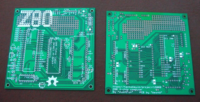
WestfW wrote 01/08/2017 at 08:05 point


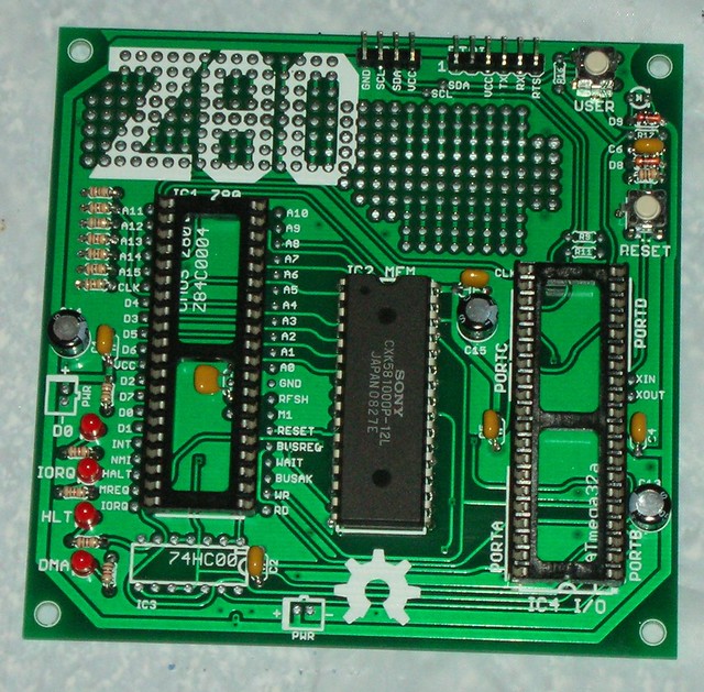
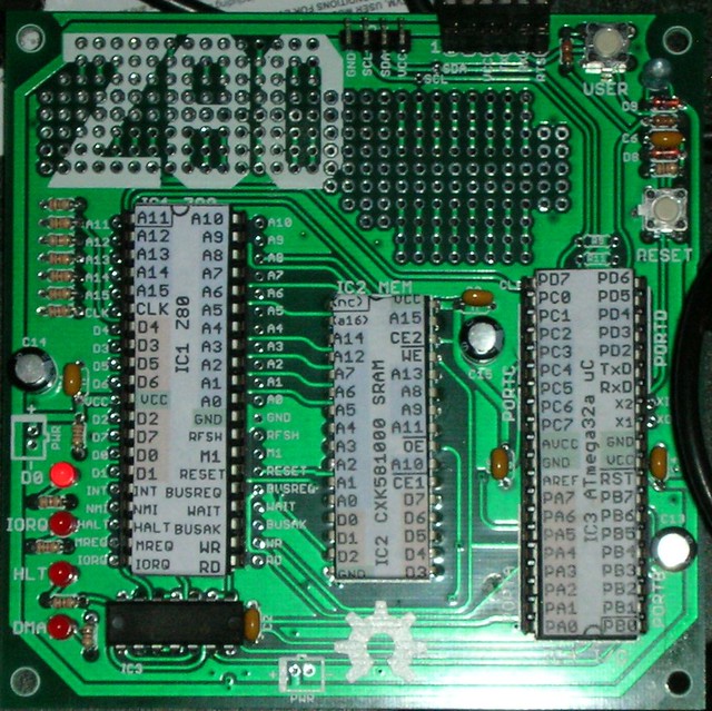
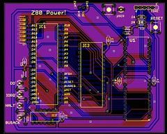
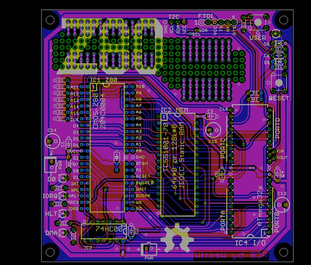
So... I've copied (most of) your PDF schematic into EAGLE and had a try at PCB:

I've got a couple of questions:

1) Why 9 address lines between the Z80 and m32?  A Z80 bootloader could be copied into RAM in far less than 512 bytes, assuming all it had to do ws load a bigger bootloader via IO.  And you might not even have to implement all 256 IO ports, since they're potentially "intelligent" enough that you don't need 32 bytes of address space to implement a uart.  (I might be trying to free enough pins for the m32 to do video...)

2) You mentioned that the m32 loads the bootloader into "high memory"; doesn't it only have access to low memory?  A9..A15 are pulled low, right?

3) Why the funky setup for the USER led and switch?  Aren't there simpler schemes for using a single pin for both input and output?

  Are you sure? yes | no

Just4Fun wrote 01/08/2017 at 10:12 point

Wow... great!! Here the answers to your questions:

1) Yes, you can use less address lines. I left 9 lines in this HW version just to be sure to have enough space for any SW update. In a next HW revision probably I'll lower them. The actual Loader (S091216) is 57 bytes long, so 6 address lines should be enough for now, also for the I/O address space (up to now the used I/O address are from $00 to $02, as you can see in the sketch).

2) Memory starts from $0000 to $FFFF. I call "upper memory" that one is at beginning, so $0000 is "upper"...

3) May be... If you find a working simpler way please tell me...

PS: please post a photo when you build it!

  Are you sure? yes | no

WestfW wrote 01/09/2017 at 23:48 point

Final-ish version.  Does anyone have comments?  It's a very conservative PCB (smallest tracks 0.3mm), designed to fill up the 100x100mm PCBs that China produces so cheaply...


(Edit: "final" silkscreen, sent to PCBWAY)

  Are you sure? yes | no

K.C. Lee wrote 01/10/2017 at 00:05 point

You should keep the silk screen (Z80) away from the solder pads in your proto area.  Some PCB vendors might remove it and some might not be so careful.

Also check your silk screen font sizes as they may or may not be visible. I usually thicken them and I know what line width and sizes I can get away from my supplier.

  Are you sure? yes | no

WestfW wrote 01/10/2017 at 00:56 point

Yeah; I was hoping it was masked, so I'll end up with white between the pads (like some of the Olimex boards.)   But results are likely to be vendor dependent.
The text and lines you see are post-widening.  They should be at least 8mils wide...

  Are you sure? yes | no

K.C. Lee wrote 01/10/2017 at 02:01 point

8 mils is a bit too thin for my PCB vendor.  On Eagle, I use 24 mil tall text and change the ratio at least to 15% and even then they failed me. 24 is a bit small.

I avoid having silkscreen any where near my pads in general as the silkscreen alignment is not reliable from my supplier.

https://hackaday.io/project/4993-dual-channel-battery-chargeranalyzer/log/17291-keeping-up-with-the-times-prototyping-with-qfn-and-bga

Just something to think about.

  Are you sure? yes | no

WestfW wrote 01/10/2017 at 02:46 point

The ratio is the text line width to text size.  If you had 24mil text with a ratio of 15%, then the line width would have been less than 4mils!  In any case, most of the "small" text on this board is 50mil high with 16% ratio, which should be 8mil for the lines making up the text...  (100mm is a relatively large board; things are bigger than they look in the picture (as opposed to when you're trying to fit things in a 50mm board, and things are tinier than you expect.))

  Are you sure? yes | no

K.C. Lee wrote 01/10/2017 at 03:49 point

I pack my boards very tightly - on dense boards about 80% of the surface area are filled advantage of those deal.  There isn't usually a lot of empty space for silk screen artwork etc.  FYI see my projects.  Hard to judge the scales as I work in 1 mil grid and mostly fine pitched parts.

  Are you sure? yes | no

Yann Guidon / YGDES wrote 01/10/2017 at 04:09 point

Hey that's awesome !

  Are you sure? yes | no

Just4Fun wrote 01/10/2017 at 10:17 point

Hi, just to say I'm currently working on a 16x GPIO Expansion Module. I think that it can be fitted inside your PCB too... It's only a DIL28 IC, some passives and two headers, and can be an "optional" hardware to assemble on it. You decide... (if you are interested I can preview the schematic draft).

  Are you sure? yes | no

WestfW wrote 01/10/2017 at 11:03 point

There's room for a 28pin DIP in the prototype area.  Does it connect via the I2C?
I think I need to get PCBs made and build this thing before I decide that it's not such a good idea, after all.  :-)

  Are you sure? yes | no

WestfW wrote 01/10/2017 at 11:04 point

Hmm.  One "problem" is that the board exceeds the 80x100 size limit of "free" EAGLE.  The main guts would probably fit in 80x100; the prototype area would go away :-(

  Are you sure? yes | no

Just4Fun wrote 01/10/2017 at 11:26 point

Yes, it connects via the I2C, and it can be easily assembled with the prototype area too...

About the Eagle limit, may be it's time to give KiCad a try... :-)

  Are you sure? yes | no

WestfW wrote 01/13/2017 at 01:01 point

Parts ordered, gerbers sent off to PCBWAY's $10 special...

  Are you sure? yes | no

Just4Fun wrote 01/13/2017 at 10:47 point

Great! 

  Are you sure? yes | no

Scott wrote 01/13/2017 at 04:46 point

Bill:

Any extra PCB's available?

  Are you sure? yes | no

marcelo wrote 01/07/2017 at 15:56 point

Hi, Is possible share the Kicad schematics ?

  Are you sure? yes | no

Just4Fun wrote 01/08/2017 at 09:15 point

Said and done! I've just uploaded all Kicad4 project files in the Files section...

  Are you sure? yes | no

marcelo wrote 01/08/2017 at 16:07 point

Great ! thank you my friend 

  Are you sure? yes | no

Scott wrote 01/03/2017 at 08:50 point

Hello:

Nice project.  I agree with Franz; will you release the bootloader, uBIOS and modified BASIC source code? 

Peace and blessings,

Johnny

  Are you sure? yes | no

Just4Fun wrote 01/03/2017 at 13:45 point

Hi, as I said to Franz, just wait some days...

  Are you sure? yes | no

Scott wrote 01/03/2017 at 18:47 point

You must have been posting while I was, thus I was unable to see your response to Franz.

Thanks!

  Are you sure? yes | no

ekaggrat singh kalsi wrote 01/02/2017 at 23:39 point

is there a way to hookup a 3.5/4.2 inch lcd  and keyboard directly? that would make a great pocket retro pc

  Are you sure? yes | no

Just4Fun wrote 01/03/2017 at 13:57 point

With "some" HW and SW chamges yes...

  Are you sure? yes | no

Franz Zinn wrote 01/02/2017 at 20:13 point

Would you be able to share the modified software source code (or orginal and patch) and a brief explanation of the modifications ?

  Are you sure? yes | no

Just4Fun wrote 01/03/2017 at 13:44 point

Ok, no problem at all... I'll do an update next days on this topic.

  Are you sure? yes | no

legacy wrote 12/20/2016 at 20:38 point

bluetooth with a smartphone? Useless as a brick, you can not type comfortably, whereas the idea at the basis of the DMA is brilliant. My 50 cents.

  Are you sure? yes | no

legacy wrote 12/20/2016 at 20:40 point

Also, I hate the price list when things come from China.

  Are you sure? yes | no

qquuiinn wrote 12/18/2016 at 02:18 point

Cool project! I like the idea of using it 'headless' over bluetooth with a smartphone, it really makes a more practical retro SBC instead of relying on old CRT displays and PS/2 keyboards like other ones I've seen. 

  Are you sure? yes | no

Similar Projects

Does this project spark your interest?

Become a member to follow this project and never miss any updates