Note: check out the prototype demos, I've attached the videos to this page, and the videos are also posted on Imgur:
https://imgur.com/gallery/lpTmvMc
Project Summary
This project outlines the hardware and embedded software design of a coin-cell powered circuit that samples ambient sound and lights up a tricolor LED when a specific musical note is detected. The LED color randomly changes over time, and the brightness of the LED is proportional to volume detected at the specified note frequency.
Project Inspiration
At a local art convention I met someone selling outdoor lamps consisting of used bottles with LED string lights powered off of small solar cells. The solar-powered string lights were purchased in bulk from an online seller, allowing this artist to focus on her project's aesthetics without having to worry about circuitry.
I wanted to design a kit in the same spirit: something low-cost, low-power, ordered in bulk, "just works" out of the box, that an artist can use without any technical knowledge. I also wanted to make something responsive to the environment: in this case, ambient sound.
I imagine a scenario in which of dozens of these devices are decorated, housed, or otherwise embedded into some workpiece, lighting up in synchrony with songs or speech.
My goal is to sell batches of these devices online at cost (maybe grouped by musical octaves), once I get the unit price down a little bit more.
Hardware Overview
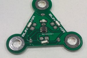
The 2-layer circular PCB has a 25mm diameter. One side holds the (electret condenser) microphone and the RGB LED. The other side holds the analog filter/gain stage, microcontroller, and the coin cell holder, which covers most of the other components. Low-cost, electret condenser mics consume current in the ~100's of uA, so the entire analog front end is powered down during sleep mode and periodically turned on to sample for the target frequency.
I chose an electret condenser mic because they were slightly cheaper than MEMS microphones. However, they can be interchanged, and if I find a similarly-priced MEMS with lower power consumption, I will probably do so. For MEMS microphones with pulse-density modulation output, some extra filtering will be needed on the front end of the analog gain stage.
I've designed a batch programming board with alignment pins and pogo pins for flashing the embedded code to each board. I intend to make a small enclosure/jig for this board to streamline the process. This board serves only as a break-out board for the programming header.
Firmware Overview
For more detailed notes on the firmware, see firmware/Readme.md on the Github page.
The firmware implements an ADC sampling scheme that allows for simple single-bin DFT processing. By sampling at 4 times the frequency of interest, you can calculate a DFT with simple addition and subtraction, no trig functions or floating point math needed. Once the real/imaginary terms are accumulated from the raw sample values, I use pow() and log() implemented with integer math and lookup tables to bypass having to use sqrt() or any floating point multiplication/division.
The calculated signal amplitude is used to determine the PWM values driving the LED's. The color is picked with a random number generator using a hue/saturation/value color scheme, and the RGB values are calculated with an HSV-to-RBG module that uses only 8- and 16-bit integer math. The color is slowly "ramped" to another randomly chosen hue/saturation, while value (brightness) is locked to the sound amplitude.
If the sound amplitude is below a certain threshold for too long, the device enters sleep mode. It periodically wakes up to sample audio. One of my work-in-progress tasks is determining appropriate threshold levels (which will vary across target audio frequencies) and appropriate timing to wake the device to poll ambient sound. The challenge is finding the right balances between power consumption, device responsiveness, and volume sensitivity....
Read more » Matt
Matt

 Gee Bartlett

 Said Alvarado Marin
 aalves
JUST REALIZED THAT I FORGOT TO MAKE THE GITHUB REPO PUBLIC!