 Steph
StephWith Our Powers Combined
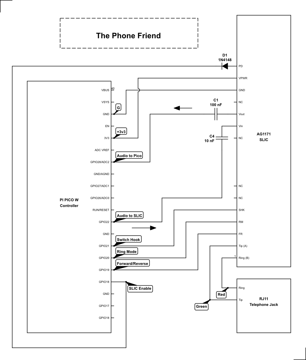
Hooking up the AG1171 to a microcontroller is pretty easy. The AG1171 only has 14 pins, and 4 of them aren't connected to anything. Of the remaining 10, a couple are optional. You'll need just a few extra components, and they're all super common:
- Two ceramic capacitors (10nF and 100nF) for the audio lines on Pins 9 and 10. You can't skip these because they are necessary for removing the DC bias from the audio signal.
- A diode for Pin 14, the Power Down pin. If you plan on using this pin for power-saving purposes, the datasheet specifically warns that this pin should only be pulled low. Applying logic high or V+ will apparently fry something, so the diode here prevents that from ever happening.
That's it.* If you don't happen to have those components sitting nearby, they are easy to salvage from discarded electronics.
If you want to use the code posted in this project, here's how I've connected the AG1171 to the Pi Pico W:
While many designers might roll a custom PCB or even just a breadboard to make the interface between the AG1171 and the controller, I employed a technique more inspired by...
...Rock and Roll
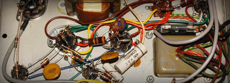
Some of the coolest early guitar amps employ a technique called point-to-point wiring. Instead of being laid out on a board, the circuit is made by connecting the individual components directly to each other. Purists say this technique sounds better. I don't know about that, but I do know it looks cooler:
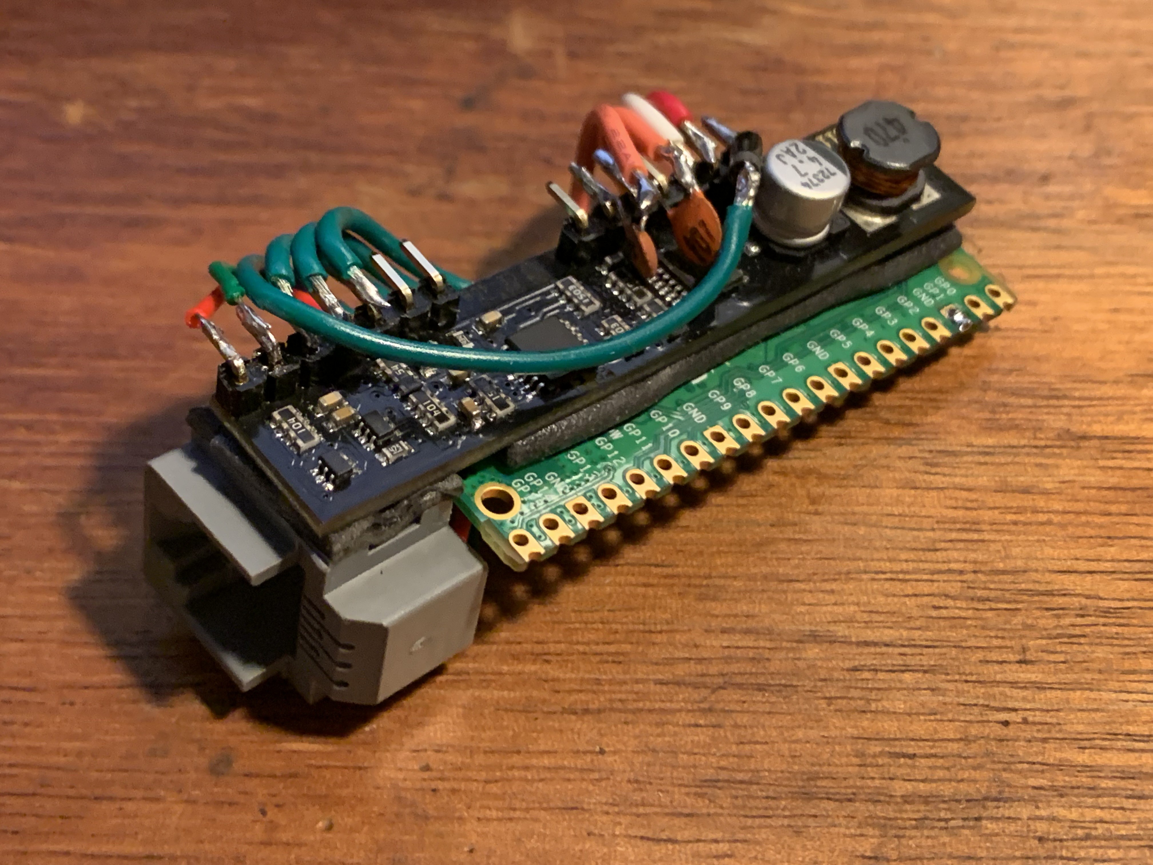
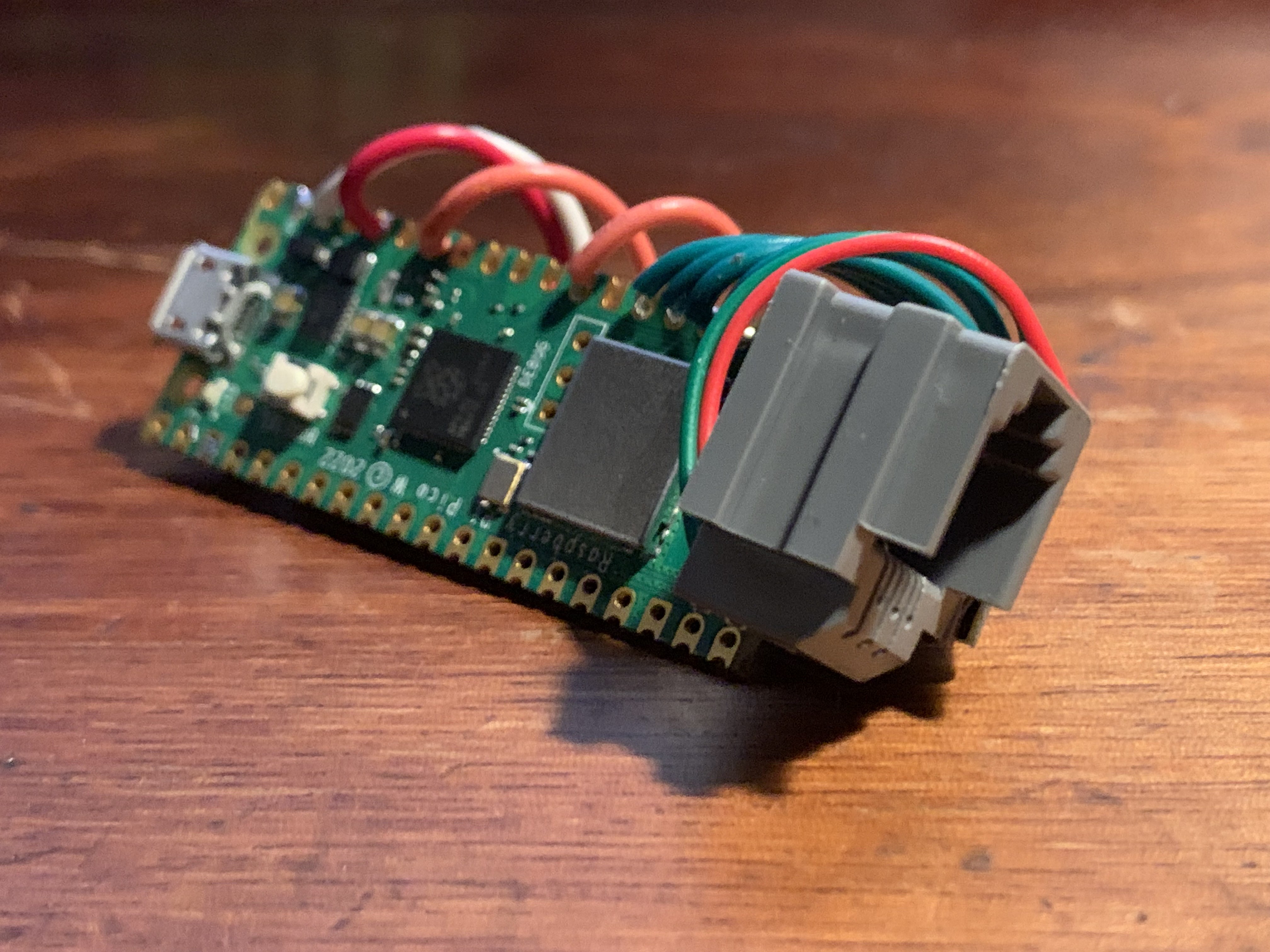
The assembled Phone Friend takes inspiration from these vintage amps. First, the pins of the Pico and AG1171 are connected directly by short lengths of wire, with the external components soldered inline. Then, the boards are folded over and attached to each other with double-stick foam. The RJ11 jack is attached in the same fashion. The completed unit looks like this:
*Well actually...
- PLEASE NOTE that for this project, I've left off a handful of external components that the datasheet calls for. I omitted the typical power filtering capacitors across V+ and GND, figuring that the supply from the Pico would be clean enough. I also omitted some diodes that the datasheet calls to be placed across Pins 1 and 2 (Tip and Ring) and GND. Those are the lines that connect to the phone. I presume they exist to protect against voltages going places they shouldn't. I can't be any more specific than that because to be honest, I don't really know. I can say this: these omissions haven't caused any trouble for the circuit as described in this project. But do me a favor and DON'T TAKE MY WORD FOR IT. If you're building a different circuit, or even if you're building the exact circuit I describe, look it over and decide for yourself. Here's the full implementation suggested by the manufacturer.
Discussions
Become a Hackaday.io Member
Create an account to leave a comment. Already have an account? Log In.