I know in the last log I said I was going to use 2020 extruded aluminum for the frame, but a thought struck me. You know what's really cheap and super easy to work with? 2x4s!!!
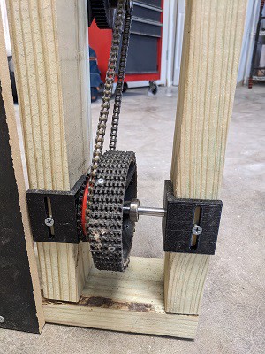
The basic idea of the frame is to take right angle brackets and on one side have a hole for the shaft and on the other have a slot. The slot will have a normal wood screw go through and allow for adjustment to tension the chain.

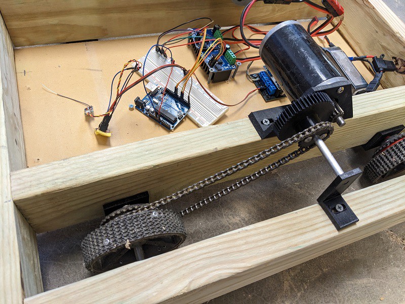
The motor mounts are a similar idea, right angle bracket with mounting on one side and slots on the other.
The shafts are all 8mm rods, chosen because 608z bearing can be absurdly cheap and have a 8mm inner diameter. Granted for this prototype I wanted to go without bearings to see how it went, and it works surprisingly well. Each wheel and motor mount needs two right angle brackets.
The wheels are left over from an old design, they're 3d printed and have rough top conveyor material riveted on. Honestly they work fairly well but riveting the tread is an obnoxiously difficult process and I'd like to explore other options.
The motors are cims with a 12 tooth 20dp aluminum pinion to 52 tooth PETG gear. A 18 tooth 3d printed sprocket is coupled on going to 32 tooth sprocket on the wheel. Uses size 25 chain.

After driving for 5ish minutes, there was no noticeable wear on the gears or sprockets. Huge success there.
The frame was made from some warped 2x4s. It's critical to try and make it as flat as possible and I didn't quite get there. But, the fact that it was still drivable is a great sign. The kit allowing for a lot of slop will make for a better first robot building experience.
| Mechanical BOM | |||
| Item | Qty | Unit Cost | Line Cost |
| 2x4 | 2 | $ 6.00 | $ 12.00 |
| Belly plate (27"x11") | 1 | $ 10.00 | $ 10.00 |
| 8mm shaft | 3 | $ 2.06 | $ 6.18 |
| PETG filiment | 1 kg | $ 20.00 | $ 20.00 |
| Cim motor | 2 | $ 35.00 | $ 70.00 |
| Pinions | 2 | $ 10.00 | $ 20.00 |
| Chain | 1 | $ 13.00 | $ 13.00 |
| Rough top tread | 1 | $ 7.84 | $ 7.84 |
| 3 inch screws | |||
| 1 inch screws | |||
| Shaft Brackets | |||
| Wheel hub | |||
| 32 tooth sprocket | |||
| 18 tooth sprocket | |||
| 52 tooth gear | |||
| 18 Sprocket spacer | |||
| 32 tooth sprocket spacer |
Hardware cost total: $159.00
(Minus motors) = $89.00
I'll go into detail about the electronics used in the next post.
Good notes
- Gear reduction and sprockets seemed to hold fine
- Chain tensioning worked well
- design allowed for slop
Opportunities for improvement
- Turning was bad until weight was added, try wider wheel base or 6 wheel drop
- Bracket across from motor needs second screw hole
- Frame rail spacing was wider than necessary
- wheels were free floating on shaft
- Did not power front wheels
- Need to explore wheel options
- Cheaper motor configuration
 David
David
Discussions
Become a Hackaday.io Member
Create an account to leave a comment. Already have an account? Log In.