The latest CAD & code has now been published! For anyone brave enough to tackle this project now I wish you luck! Only recommended for advanced users until the calibration issues get sorted.
The wheel origins were covered in a different log but, in summary, the overall geometry is based on the Baddy open source projects' wheel with an adjusted mounting hole pattern to suit the motor and mounting I planned. I also followed Benoit's suggestion that rubber hardness should be 40-50 Shore A.
Based on the application I decided that Urethane would be best as it has high wear resistance, is readily available, and is easy to cast. Armed with these knowns I went to my favourite supply store and used their expertise to select my final products.
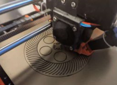
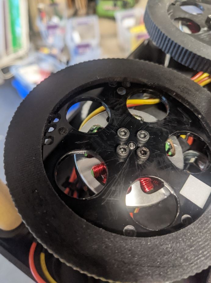
Due to the high speed of rotation and need for balancing I decided to have the hubs laser cut out of Acrylic to ensure they are strong and solid.
Casting
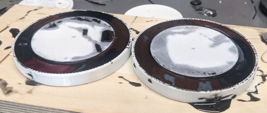
The wheel casting process was performed based on the manufacturers recommendations with the following notes:
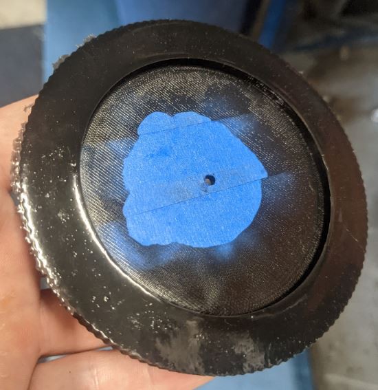
Use painters tape to cover both sides of the hub then trim the tape using the top cover as a guide. This will prevent the Urethane from filling the larger holes as well as protect against any skin forming on the surface of the hub.
Install the taped hub into the printed mold and install the top side cover.
Mix the Urethane according to the manufacturers directions. Each wheel requires about 35mL. I prepared 50mL per wheel to be safe with plenty leftover.
Pour from a height so the stream thins out and breaks any bubbles.
Wheel Balancing
Due to the high speeds of rotation it is incredibly important to properly balance the wheel so that it can safely spin at the high RPM's. To do this I used a prop balancer to find the heavy parts of the wheel and removed rubber or rim material with a small drill bit. However, I believe this could be done more easily and more cheaply as noted in the section 'Thoughts on the Future'.
If I was to make new wheels I would consider changing the wheel design to cast in a mean for balancing, and I would design tooling to balance without a purchased prop balancer.
Wheel Design
I would look at casting small features into the wheel that are made to be removed. This could either be small tabs of rubber on the ID that could be cut away, or plugs that go through the hubs.
Balancer
One option would be to 3D print a prop balancer of the classic design similar to the one I purchased. However, there's another type of balancer called a pyramid balancer that could be replicated even more easily. A paperclip can be bent to act as the pivot tower while a small hub can be printed to act as the wheel center. This combined with a wheel design that can be easily adjusted would make this process much more user friendly.
In order to keep the project cost low and accessible I decided to use 3D printing for the majority of the design. 3D Printing has many benefits including low cost, high availability, and very high design flexibility. All of the printed parts are made out of PETG because of it's strong performance characteristics and ease of printing and they were printed on a Prusa MK3.
There are only a few items that were not printed:
Trajectory Pivot Shaft - I decided to make a shaft out of steel round bar. I purchased a short length of it at Home Depot and cut it to length with a hack saw. I filed a flat near each end and drilled a hole for cotter pins to hold it in place. I used the cotter pin approach because it was easy to do with minimal tools compared to circlips or other methods.
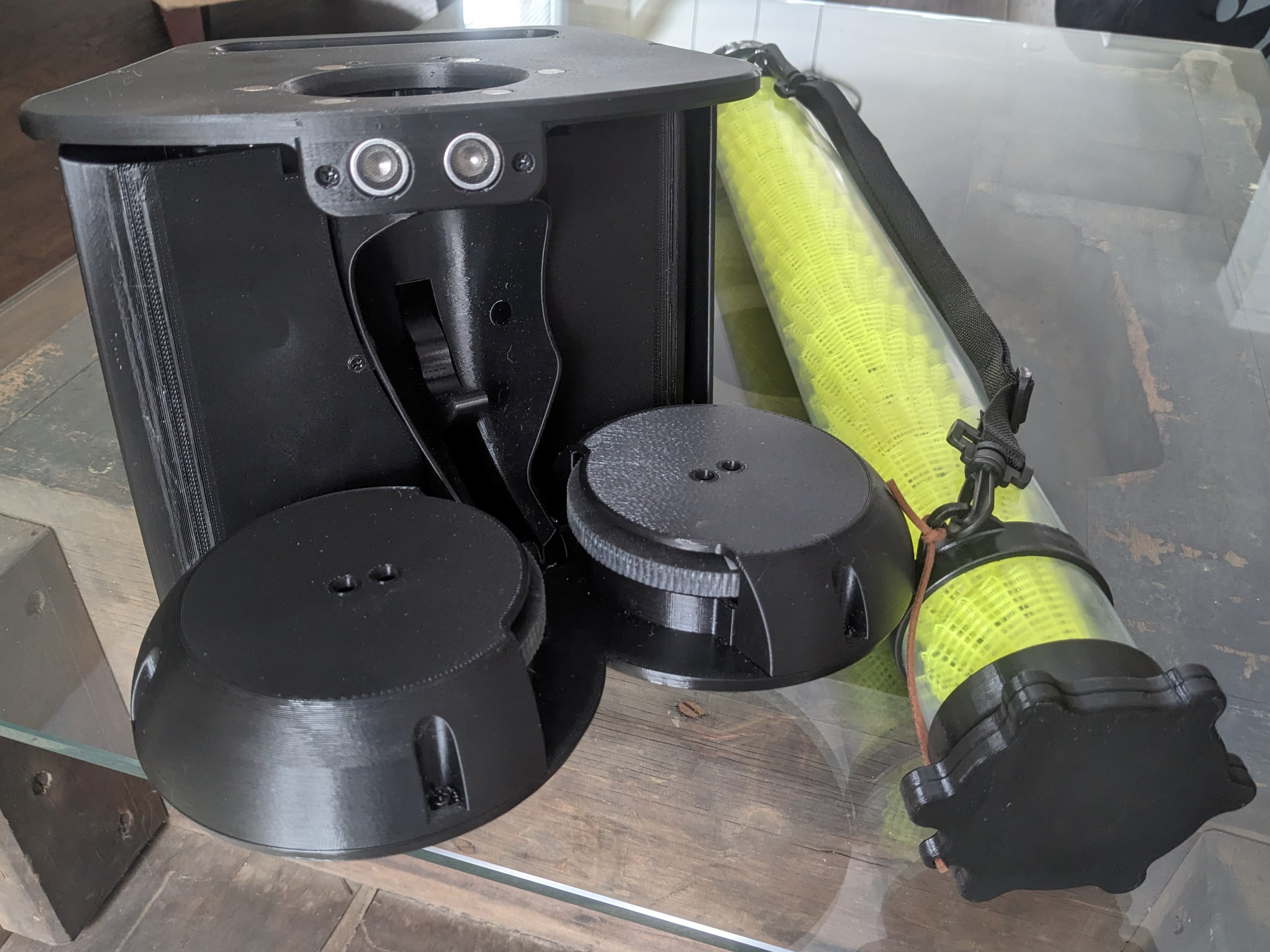
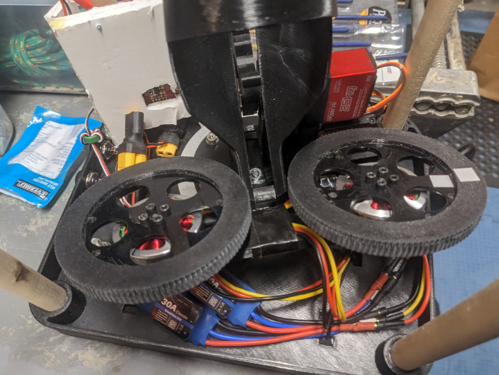
Wheels - Due to the high wheel speeds (7000 RPM) and shock loading I decided to laser cut the wheel hubs out of Acrylic as the design was already proven on the Baddy project. The urethane rubber exterior was then cast onto the acrylic in a 3D printed mold. The wheels were balanced using a cheap prop balancing rig by drilling holes in the heavy areas. I have some ideas on how to improve this process, but I expect wheels will also be available amongst the community. I plan to release a detailed log on making these in the future for anyone that wants to give it a try.
Hardware - Screws and heat-set inserts were purchased off of Amazon.
Electronics - The majority of the items were purchased off of Amazon.
Magnets - Used to magnetically couple the shuttle tube to the baddy launcher. These were purchased from Lee Valley and glued in place.
Shuttle Tube - This clear tube was purchased from Amazon.
This printed approach limits the number of separate parts and makes the build process straight forward. All of the component mount locations, cable tie-down points, and other features can be designed into the parts directly.
Print Parts & install heat-set inserts.
Purchase or manufacture non-printed parts.
Assemble electronics.
Download firmware to ESP32.
Connect to the ESP32 and command servos to their setup positions.
Power off & assemble the launcher.
Power up & configure servo positions.
Get Training!
It is still an early prototype but if you're eager to get going the CAD & Code can be found on the projects github page. Keep in mind that since this is a high speed kinetic launcher it can be dangerous. Build it at your own risk! https://github.com/TheSinc/BadmintonAce/
It's been a lot of work getting here, but I finally have version 4 coded and running enough to launch some shuttles. Through the build & programing I've identified many areas of improvement, but I am really liking where it's going.
Next Steps..
Calibration
This is the real bear I have to face. Since I've decided on a UI where the user tells the shuttle where to go on the court all of magic happens in the background. This means that we need mathematical models to determine the wheel speeds and these must be perfect for a good shot accuracy & user experience. How does a user calibrate this or adjust it if it's wrong?
There are many places this can fall apart:
Flight Trajectory - The shuttle path estimation is performed using a flight algorithm from Hugo Janton (see log 'User Interface - Version 2' for details). This will only be accurate for a specific shuttle type (feather/plastic) and geometry (brand variances). I'll need to validate this and determine an appropriate way to adjust & calibrate for different shuttles. If this model is incorrect the calculated launch speed will be incorrect so all subsequent steps will be incorrect.
Wheel Speed - Once a launch speed is calculated it must then go through another algorithm to determine the required rotation speed of each wheel. When the wheel speeds are perfectly matched the shuttle should fly straight and the required wheel RPM easily calculated based on the tangential speed components. However, the wheel speeds will not always be matched. This could be desired because the +-19 degree of physical rotation on the launcher is not sufficient to reach the desired court position, or because we want to prevent or limit physical rotation to add deception to the shots. In these cases we'll vary the wheel speeds to angle the shots. I believe this speed mismatch will result in a sort of rolling motion where the shuttles center-line speed is roughly based on the lower wheel speed + 1/2 the wheel speed difference. Is this correct? Do the wheel speeds synchronize when the shuttle jams between them? Is it consistent across all wheel speeds and speed differences? If this model is correct we'll command the wheels to go at the wrong wheels speeds.
Wheel Speed Execution - After the desired wheel speeds are calculated in the step above, we then must convert that wheel speed to a pulse width modulation (PDM) signal that can be sent to the electronic speed controls (ESC's). The translation of the desired speed to the appropriate PDM signal is important. If we have determined the wheel must rotate at 1000 RPM, but in reality it's only rotating at 800 RPM then of course the shuttle will not land where expected.
Each of these areas will need to be broken down and tested and accounted for in some sort of calibration procedure when dialing it in. That procedure will need to be documented and coded into the final system.
Code Completion
The code is very much a work in progress. When I ended the last test session you could only stop feeding by pulling the power due to code issues. I need to work out the bugs, add the code related to different presets (loading, saving, and editing), add in the calibration routines & parameters,finalize the mathematical models, add in data sanitizing, error checking, clean and comment the code, and more...
Testing
Testing is just beginning so a lot of reprints and running is needed to eliminate miss-feeds, improve accuracy, and determine if the physical parts can last. Calibration and testing is the hardest to sort out right now as I don't have any indoor space large enough to test in. Long term I'll probably need to rent out some court space to test properly, but I'll need to get the basics working first.
A few of the known issues:
Attachment of upper plate assembly to main body is not sufficient.
Wiring and wire paths need to be adjusted.
Miss feeding - Likely related to shape of chute and/or pusher.
Accuracy Poor - Likely related to shape of chute and/or pusher.
Sonar sensor must be relocated to the rotating chute as the rotation of the launching direction exceeds sensing capabilities.
Through-Beam IR sensor needs a more extensive light trap to allow it to be used outdoors at all times of day. This is why it's taped off in the video.
Long run testing.
Stiffening components.
& more...
Documentation
The documentation side of making a project I can share with the world is not to be overstated. There's a lot to do to make it ready for other to follow along and build.
Electronics
To make this more accessible I need to properly document the wiring and look at making a custom circuit board.
With version 2 of the application I decided on a radical redesign. Version 1 was very functional but it was hard to adjust the shots quickly. When a beginner player came to try it there was no way to reduce the difficulty without just limiting the shot pattern or reprograming all 9 shots. I wanted to fix these issues and make it a lot more friendly and so I came up with the idea to use a full interactive 3D interface. I'm working on implementing that but I'm very excited about what it allows.
This type of 3D view is often created with the assistance of a library, but I was concerned about trying to fit one onto the microcontroller so I decided it would be best to keep it as small as possible by writing it without any libraries. While learning about these options I came across 3D plot code from Frido Verweij which showed this was possible and laid the ground work I needed to proceed.
That example was designed to show a single math function and only allow rotation of the view so there was a lot of work to make it work for this application:
Added zoom and pan functionality (touch & mouse)
Added plotting of lines, court plane, nets, launcher, shot positions, etc.
Added shot markers and the ability to resolve & adjust their position on the court once it's rotated in the 3D view.
Added the ability to create, modify, and clear shot sequences.
Added Play/Stop button to start and stop the feed.
Added full flight path modeling and velocity solving.
& more.
Main Page
Here the user will be able to adjust shot placement and create shot sequences along with all other controls needed to run the launcher.
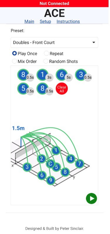
The presets allow pre-population of the shots based on court size (Singles vs Doubles) and training type (Full Court, Front Court, Service Return, Out of Bounds, Locked Rotation, etc). After they are populated the shots can be adjusted directly on the court if needed.
As with the version 1 interface, the user can select the play type: play once, repeat the shot pattern continuously, mix the order of the selected shots, or fully random. I may remove the fully random shots as I think the user should add all 9 shots with desired delays based on shot type then mix up the order of those.
To add a shot to the pattern the user simply clicks on the shot indicator on the court in the desired shot order. The delay will be based on the currently set default but can be adjusted by click on the delay value in the pattern. The shots themselves can be removed by clicking on the number in the pattern or by using the clear all button. If the shots are not landing where expected or the user wants to make a change they can do so directly on the 3d view. More information on that can be found below.
Shot placement can be adjusted by simply dragging the shot marker. Green flight paths & markers indicate that a valid solution was found by the solver while red means the shot placement cannot be achieved based on the current constrains. This is dependent on the selected trajectory, current physical head rotation, and the maximum angle that can be imparted by the feeder wheels.
Currently the solver is set to allow 15 degrees of angle to be imparted by mismatching the two feeder wheel speeds. In the below graphic the head has been set to be rotated to +20 degrees, but the angle needed for the shot is close to 0 degrees. Since the feeding wheels can only impart 15 degrees of correction the shot cannot be achieved (5 degrees off).
Using the wheel correction to impart angle can be a valuable tool to allow the launcher to be deceptive (up to +-15 degrees) or to allow a locked mode where the head does not rotate at all to avoid telegraphing the next shot.
The flight trajectory is based on a paper from Hugo Janton from 2019 where he analyzed the Baddy launcher. His algorithm plots the flight path given an input velocity and angle. I've implemented a simple method that calculates the distance from the launcher to the shot landing point then uses that to find the input velocity. While I'm sure this could be solved directly I opted for a simple brute-force method:
The algorithm takes a target distance and lower and upper velocity as it's inputs. The distance the shuttle would travel at the lower and upper velocity is calculated. If the target distance is not within the lower/upper range the shot cannot be achieved. If it is within the range then the average of the two velocities is computed and that shuttle flight distance is calculated. If that's within our acceptable shot accuracy then the shot is considered solved and that velocity value is returned. If it's not, we compare the mid-point distance to the target distance. If the target distance is greater we'll repeat the same process using the midpoint as the lower velocity. If the target distance is smaller we'll repeat the process using the midpoint as the upper velocity. We keep doing this until the desired accuracy is achieved then return that velocity.
Eventually we'll need to convert this velocity into wheel RPM's. With zero wheel imparted angle this should be fairly straight forward but with mismatched wheel speeds it will not be. There is a lot of work to do to see if Jugo Janton's model is accurate for the flight path and to develop a model for the wheel speeds given the required target velocity and imparted angle. At the moment I've only planned in a global velocity correction but I'm not sure if that will be enough. Do I need to have an correction on the wheel angle correction? The drag coefficient? We'll see....
At this point the UI is looking pretty nice but with such a major re-write all the firmware needs to be rewritten almost in it's entirety. So today it's just pretty pictures and a need to get back to work.
When deciding on the software for this project I wanted to avoid the need for a custom phone application. This was to avoid developer licensing and costs maintaining such an app in android and IOS. It would also result in a more complex system that could not be easily modified by users. Instead I decided to use an ESP32 microcontroller as a wifi access point that would serve a simple web page. That web page would communicate with the micro-controller through a web-socket and JSON for a nice simple responsive system.
ESP32 [C Code] <-- Web Socket [JSON]--> User Phone [HTML + Javascript].
In this post we're going to focus on the user interface design. Originally I wanted it to be as simple as possible so I could start testing the system. The general workflow was influenced from screenshots of the Baddy UI I had seen in reports and online. The user could select from a series of 9 shots that could be calibrated individually in a separate section. Changing the shot in that section would be done by adjusting the 4 parameters: Left Feed Wheel Speed, Right Feed Wheel Speed, Trajectory, and Rotation.
This UI was operating successfully but was never polished up as I decided to abandon it for a shiny new generation UI. While perfectly functional, this version had limited adjustability and required a lot of user testing to find the right shot parameters. The hope with the new UI is that the user will tell the system what kind of shot they want and the code will do the heavy lifting to determine the wheel speeds and all other functions.
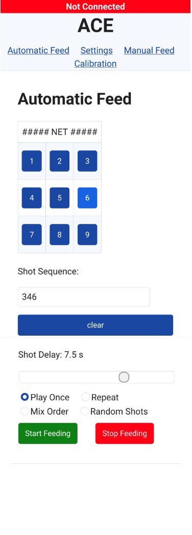
Automatic Feed
Here is where the user would enter in a shot pattern for training. The user could click on the shot ID buttons to add them to the shot sequence or manually edit the shot sequence. The delay selected would be used between all shots. They could also chose the shot order: play the pattern once, repeat the pattern continuously, use the entered shots but randomize them, or do a random selection of any of the 9 shots.
Automatic Feed
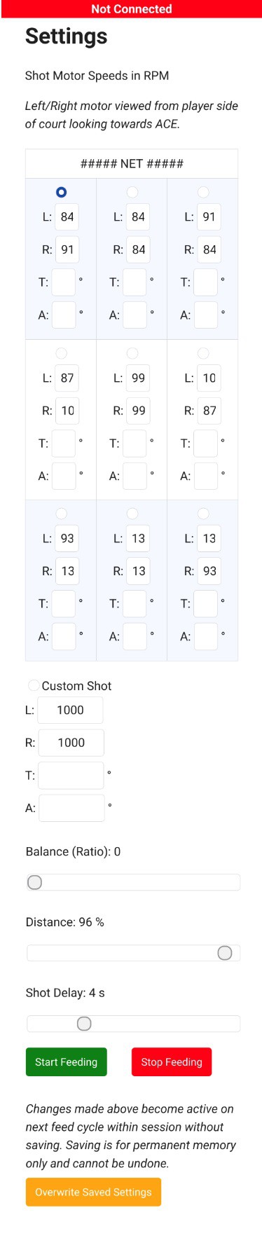
On this page the user would adjust the settings for each of the standard shots. Selecting the shot would have the shot parameters load into the lower sliders where they can be adjusted. To simplify the entry the sliders calculate the balance (speed mismatch between the two feed wheels) and the max distance the system can achieve (based on max RPM) so that the user does not need to work directly in RPM. The custom shot option could be used for testing new shots before over-writing values on the standard shots. Shot parameters could be saved to memory for future use.
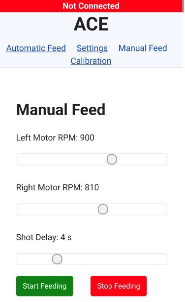
Manual Feed
This was mainly used for testing but ultimately wasn't required because of the custom shot option on the settings page. Users can set the wheel motor speeds directly on this page, but it was never expanded to include trajectory and rotation.
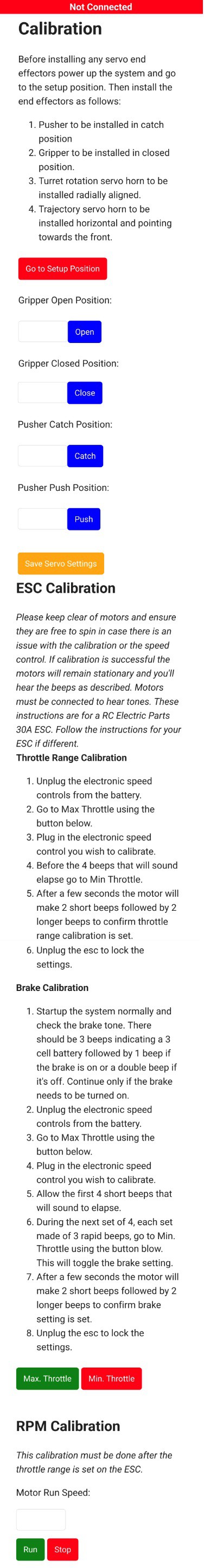
Calibration
This page was used to prepare the system for first use. The servo arms need to be attached at the correct positions to avoid any jams or other issues during startup and the rotation amounts adjusted. The ESC's also need to be calibrated.
Version 2 seemed to be working pretty well, but I was not comfortable leaving it unattended because it lacked proper guarding and I did not think my original guarding plan would be sufficient given the amount of movement (rotation & trajectory).
So I decided a new version was needed and made my upgrade feature list:
Redesigned with guarding in mind. Minimize access and pinch points.
Dedicated electronics & battery mounting.
Proximity sensor to detect people standing directly in the shuttle path.
Through-beam IR sensor to detect shuttle run-out.
Radical user interface redesign.
Carrying handle.
Nicer form factor.
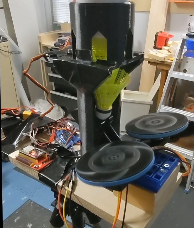
It's this build that I am working on right now. I've completed a preliminary mechanical build and completed a good portion of the user interface redesign. I still have to rewrite the firmware before I can even start testing.
Once it's running that will just be the start as no versions of the launcher have even been on a court. I'll need to calibrate and test precision and reliability. I've already identified problems that have to be addressed on the next version and I'm sure testing will find many more.
There is a long way to go to get this finished, documented, and shared, but I'm really excited to be sharing it with everyone. I'm also thrilled to see it looking like a real product!
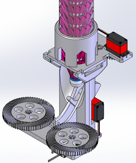
In version 2 I explored using a single motor mechanism to feed the shuttles into the wheel. I decided that this was more mechanically complex and would require extra sensors & a continuous rotation servo or stepper to operate. I decided instead to continue building off of the V1 design.
Version 3
After testing of the hacked together version 1 I had a list of changes to make for the next version. Some of those were:
Add tower rotation for better court coverage
Mount gripper separately from tower so the shuttle stack does not rotate with the tower
Pincer gripper redesign
Add functioning trajectory controls
Make proper feed wheels
Add enclosure
Add stop/start buttons
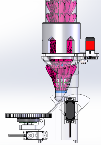
Rotation Mechanism
In order to keep costs down I started with a very low cost 4" turntable bearing from Amazon. Using a bearing minimized the forces needed to turn the unit and the large form factor provided mounting holes and good stability.
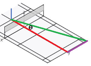
To determine the mechanism needed to rotate the tower I first had to identify how much rotation was required. I decided that doing a direct shot to the far court corners would be a good metric as this is a challenging shot to return so would be very valuable for training. Pointing directly at the corner would allow the feed wheels to run at equal speed and give the best chance of achieving the corner shot. Since I intended to place the launcher at the service line on the far side I could calculate the angle of the launcher for a direct shot.
While larger angles would be needed to drop to the near-net corners I wanted to limit the movement to make guarding the device easier. I also surmised that +-19 degrees along with the direction compensation that can be achieved by mismatching the launcher wheel speeds would be enough to hit these corners. This has not yet been confirmed.
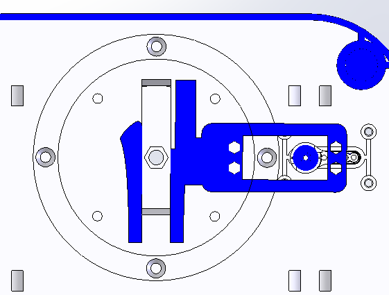
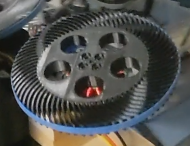
At first I considered a geared option but this would have required the servo motor to be very far away from the tower center to provide room for the gear. With a servo that can only rotate 180 degrees the servo mounted gear would need to be quite large.
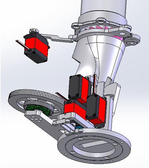
Instead I decided to use a cam follower & track method which is even simpler in its construction. The servo arm has a small post mounted to it that runs inside a groove mounted to the lower plate. I kept this separate so that it could be replaced if needed and connected it with thin walls so it might break-away in case of a jam during testing.
In a future post I'll go through the basic inverse kinematics used to determine the required servo angle based on the desired turret angle.
Trajectory
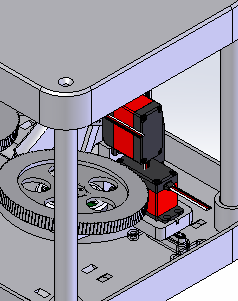
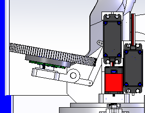
In order to allow the launcher to achieve many shot types I included the ability to change the trajectory for each shot. This should allow a high clear, drive shots, and drop shots. This was achieved by mounting the motors to a pivoting platform connected to the servo through a linkage. By changing the servo angle the platform position can be adjusted.
In a future post I'll go through the basic inverse kinematics used to determine the required servo angle based on the desired shot trajectory.
Gripper
The original gear train had a few downsides:
Backlash - With 3D printed gears designed to be easily printed the backlash is high. Given the full travel of the grippers is only 10 degrees or so the unintended movements were quite large.
Poor Resolution - Since the full travel was such a small amount the adjustments were quite coarse.
Risk of overtravel - There were a lot of values that could be entered during calibration that would result in a crash since it was using such a small portion of the servo 180 travel.
Servo Position - The servo needed to be quite far back in the launcher which limited design freedom.
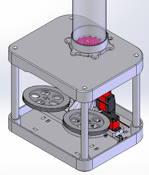
On the new design I kept the gearing between the two gripper arms, but then connected the gripper to the servo using a simple linkage.
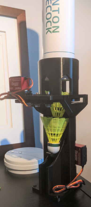
Enclosure
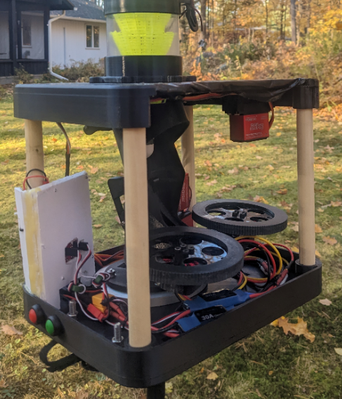
To minimize print time I decided to print top & bottom plates then space them apart using wood dowels. I would then skin it with a thin walled 3D print or a lasercut panel.
When designing something new there's always things you didn't know that come out during testing so it's incredibly important to put together a proof of concept to learn as much as you can as quickly as you can. The first version of the launcher was always meant to be a rough development platform to review the concept, electronics, and programming. To create this design I started with the system constraints/knowns. These can come in a variety of forms: capabilities, physical, financial, manufacturing process limitations, etc.
Financial
Relatively low cost but feature rich (Below $1k)
No hidden part costs (ie. I used these $500 motor controllers I already had so they are free!)
Manufacturing Process
3D printed parts wherever possible
Non-printed parts should be easily manufactured using minimal equipment
Physical
Easy to transport
Battery powered
As small as possible
As safe as possible
Miscellaneous
Easily available parts for others to duplicate
Capabilities
Good court coverage
Trajectory control
Rotation control
Programable shot pattern
Adjustable shot calibration
Launching Wheels
I started with the Baddy wheel design as it was proven so would be safer/faster than designing one from scratch.
Using that geometry as the known we can calculate a rough estimate for the required rotation speed to perform a smash. A good smash is 100m/s and the wheel diameter is 104mm.
Solving for the rotation speed omega gives:
Where omega is in rad/s, V_tan is in m/s, and r is in meters.
This gives a rotation speed of about 1923 rad/s. We can convert to rotations per second by dividing by (2*PI), and multiply by 60 to get the rotations per minute. This gives 18,364 RPM. Since this ignores many factors, such as slip between the wheels and shuttle, the real motor speed would need to be even higher.
For the wheel motors I wanted to use brushless motors such as those used on drones. These tend to be rated by kV which is the motors' unloaded RPM/Volt. Since I was considering using a common 11.1V 5000mAh 3S LiPo battery we can divide out the desired RPM by 11.1 to determine the required motor kV of 1654. In reality to achieve this smash speed we would need a much higher KV to account for the loaded motor speed, losses, and the voltage drop of the battery over the session.
However, if we then consider a drop shot of 10m/s we would only be at 10% of the motor's maximum speed. Since most brushless motors and ESC's without feedback don't operate well below 1/3 of their max speed we can't handle such a powerful motor, so let's start from the drop shot instead. At an estimated 10 m/s we'd need a kV of 165 RPM/Volt so if that was 1/3 of the motor's maximum it would have a kV of 495 RPM/Volt. Recalling all of the factors that result in this number being low I'd estimate we want to be above 600 kV.
In the end I selected a 750 kV motor which was close to the target value. I suspected that the large diameter form factor of the selected motor would have a stronger bearing to take the shock loading of the feeding sequence and provide higher toque compared to a smaller motor. Its short length also helped minimize the height of the launcher.
While I'd adopted the general wheel geometry from the Baddy project I needed one that could mount to the selected motor so for the initial testing I decided to try a complaint wheel 3D printed entirely out of PETG. This worked relatively well when a rubber band was glued around the outer diameter but the band failed quickly.
Trajectory / Rotation / Gripper / Pushers
In order to speed up design and reduce risk I eliminated the trajectory & rotation features from the preliminary build. While the force for the gripper & pusher is very low I settled on a two low cost 25kg servo motors with the intention of using them for all 4 controls in the final design.
For the catch/push arm I directly mounted it to one of the servo horns included with the servo.
For the gripper I decided to use a simple printed pincer gripper with a gear train to drive it. This style of gripper would take up less space in the final build then many alternate designs. Eventually I changed the servo gear to one using spokes so that a jam would result in the gear breaking away instead of burning out the servo motor.
Launch Tower
For the initial test I wanted to keep things simple and avoid a full housing. The tower would have mounting locations for the servos, motor mount board, and hold the top assembly containing the pincer assembly.
Electronics
I considered a few options but eventually settled on an ESP32 development board for its low cost, wifi capabilities, and high pin count. It's very popular which means there are many libraries and resources to learn from.
For the brushless feed motors I settled on 30A ESC's. They needed to be low cost and have braking to slow down the motors quickly for safety.
To power the servos and feed the microcontroller I purchased a 3A 5V step-down module designed for hobby drones. I was trying to avoid a custom control board so chose external self contained modules wherever possible.
Completed Assembly
For the initial testing the tower was screwed down onto a wood board and mounted to a tripod. The electronics were attached on the back of the board for the testing.
Like any great project this one started with a pure and noble purpose: To improve my badminton skills to outperform my older brother. We've always played together and were fairly closely matched, but that all changed when I took a few years off and returned a feeble opponent. Having previously had a very brief opportunity to train at the wonderful BC Drop Shot in Netherlands (https://www.bcdropshot.nl/nl/), I knew that I needed to add skills training to my routine instead of just playing matches. Since the Netherlands is too far a commute from Canada I was left with only one possible option: to buy or build a robot friend to train me.
At first I searched online for opportunities to purchase one and there are some impressive offerings but they're mostly geared towards high performance clubs with price tags that match (>$2K). On the lower end there's a cheap option for around $200 available under a number of brand labels, but it's treated as a disposable item that cannot be serviced and provides little control over the shots.
Eventually I came across a impressive open source project by Benoit Greslebin called Baddy where he designed and built a launcher along with apps to control it. Ready to buy and build I headed to purchase a kit only to find that the project is defunct with no available parts, support, and only much older project designs on-line.
I could have stopped there, but every great story has a setback and where would that leave me? No, I had to proceed on my own. So I took the features of Baddy I liked and started designing a launcher from the ground up to be even more capable and accessible.
From this the project goals were formed:
Low Cost - Somewhere between the cheap and professional options.
Feature Rich - Examples:
Maximum Court Coverage - Include head rotation & shot trajectory to allow a wide variety of shots.
Adjustable Shot Positions - Ensure the user can reprogram shot positions based on their shuttle type & training needs.
Adjustable Shot Patterns - User can set a shot sequence & delay.
Portable - Since this will not stay at a club it needs to be easy to transport & set up.
Mostly 3D Printed - With the explosion of 3D printers this makes the project more accessible.
No phone apps - Having dabbled in these before I knew I didn't want to spend my time and money maintaining apps for Android & IOS forever after.
Safe - While a machine like this will always have some risk I wanted to make it as safe as I could reasonably make it.
 Peter Sinclair
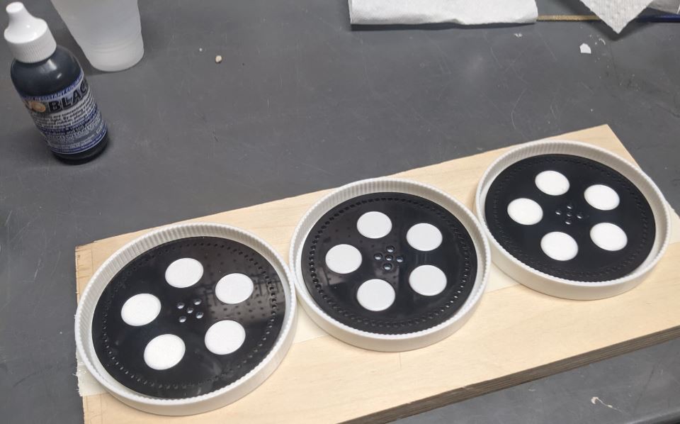

 Automatic Feed