 Arya
AryaWhen I was sourcing parts off Taobao, I ordered wrong display breakouts. They looked just like the ones I was supposed to buy, with two small differences - GND was swapped with VCC, and pin header had RST instead of CS. First problem caused me to burned a panel or two, second problem made me waste a week or two of my time. Here's how it goes:
The ZeroPhone has expansion ports. In particular, there's a 13-pin expansion port on the side, with SPI-0 port on 4 of them. SPI is a really popular communication standard, you can use it to re-program BIOS chips, ATMega/ATTiny/other Atmel chips, show things on LCD/OLED/E-Ink displays, communicate with SD cards, RFID readers, thermocouple amplifiers, GPIO expanders... I have designed two mod boards for this exact headers, and I wanted to include them in the package sent to reviewers and contributors - because I believe it's important to show that ZeroPhone also has tools that make hardware experimentation easier.
SPI uses the CS pin to signal, which peripheral it currently wants to communicate to. SPI-0 on the Pi has 2 CS lines - one goes to the display header, another goes to the expansion header. If, however, the display doesn't have the CS line exposed, then there's no way to signal to the display that it's not supposed to receive information at this point when, for example, there's an RFID reader on the expansion port. The result will be, at best, garbage shown on the display - at worst, the display might interpret commands sent to RFID reader as commands for the display, and it might even damage the display.
So, just re-wiring the breakouts, swapping RST with CS, should be easy? After lots of broken panels and wasted time, I understood this wouldn't be the case.

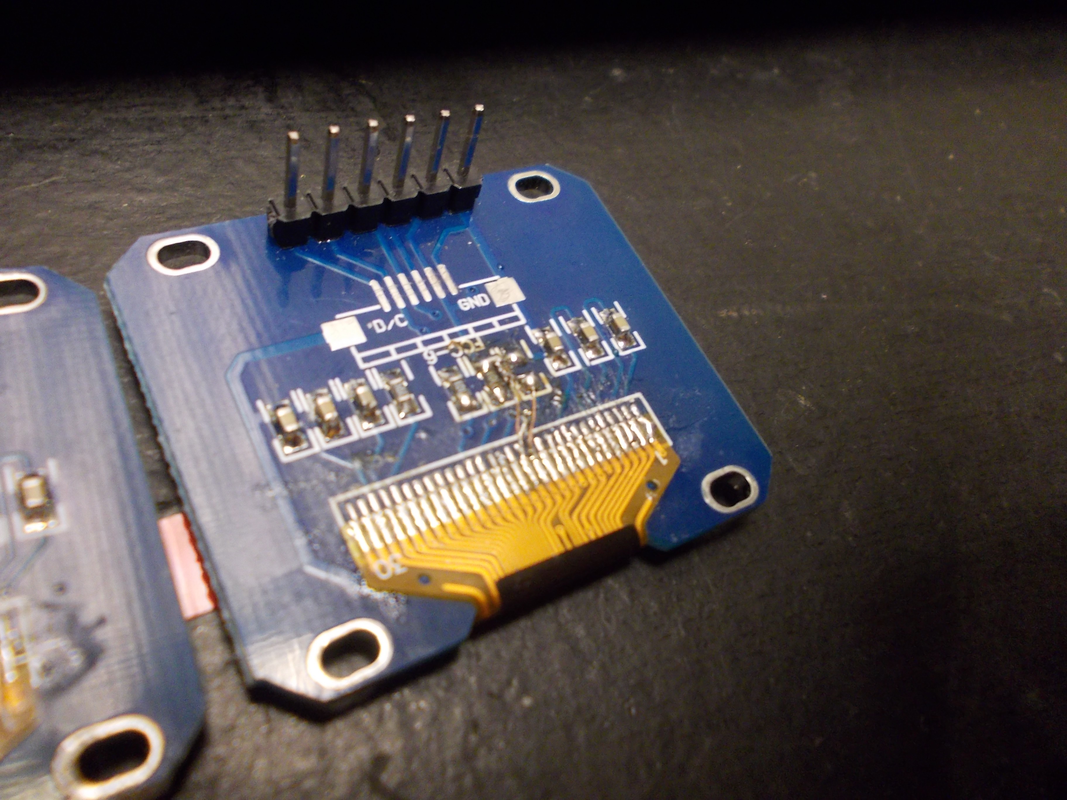
First idea was to cut out the RESET signal from the OLED panel FPC and short CS signal to the pad that RESET pad of the FPC was supposed to connect to. However, it turned out that CS pad was shorted to ground - and the trace couldn't be cut, because it was on the section of breakout PCB that was under the flex cable. Oops. I decided to disassemble all the displays, that is - unglue the OLED panel and desolder the panel FPC from each board, then set panels aside and work on modding the PCBs. Panels were desoldered (with 1 or 2 lost to "broken panel edge" problem) and left on a table at the hackerspace. In a couple of days I went to collect them to put them all aside, only to find that, apparently, somebody has dropped something heavy on them, breaking 5 panels. Oops. Lesson learned, I guess.

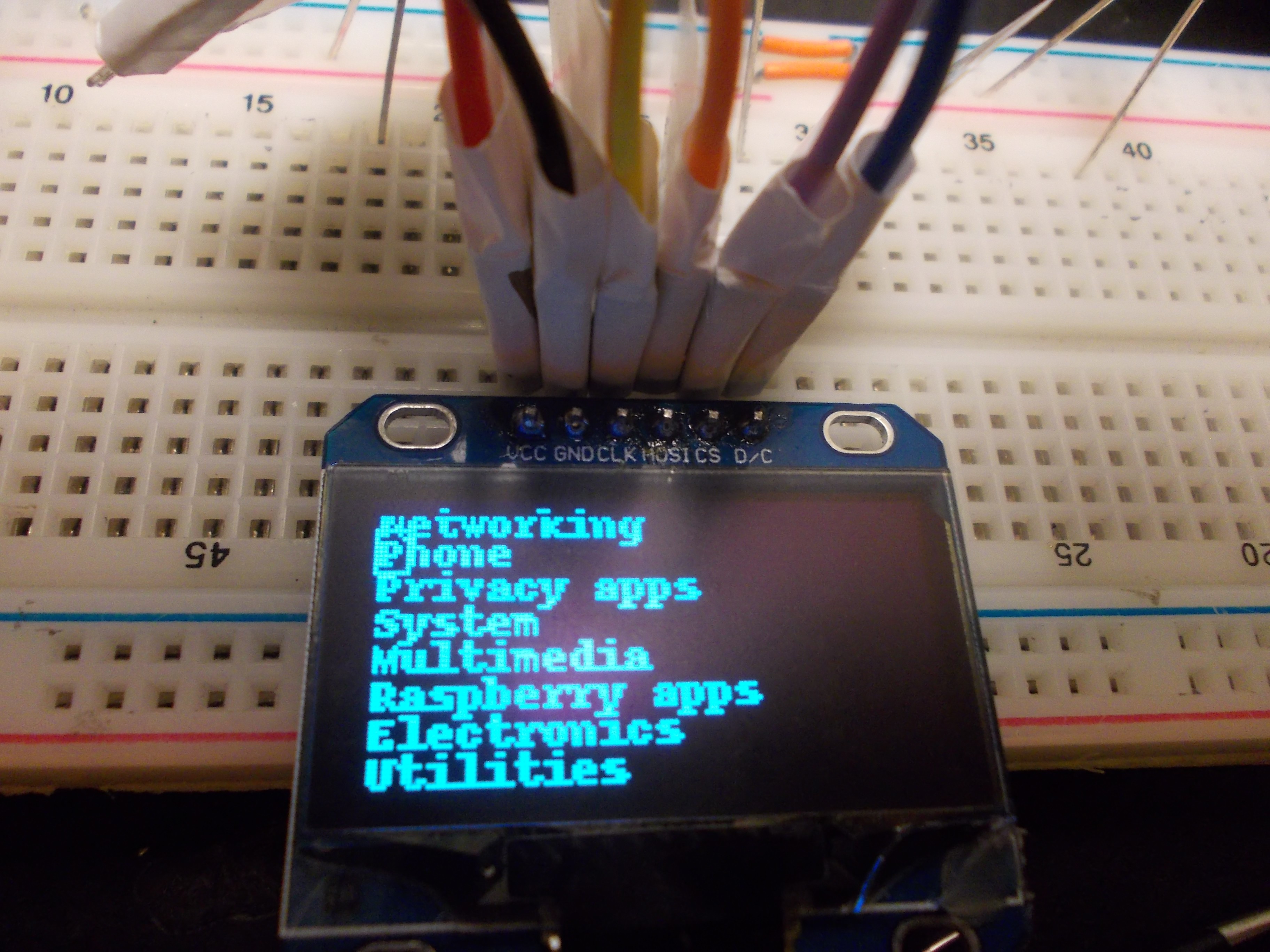
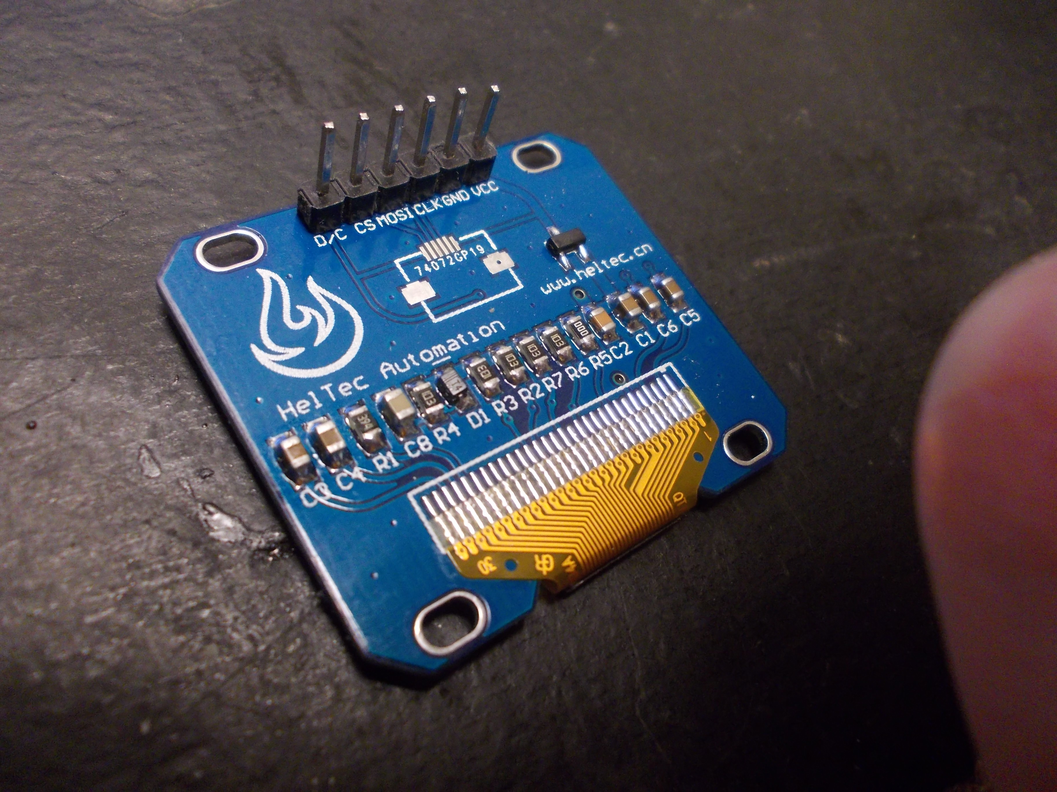
As I got the panels separated from breakouts, I could try putting panels on 7-pin breakout PCBs I had, which have both RST and CS available. They worked, so the panels were, supposedly, similar - the difference must have been in the breakouts. I didn't have enough 7-pin breakouts, and they don't fit the ZeroPhone that well anyway (they're kinda ugly and have oversized outlines), so I had to get the CS signal on the 6-pin breakouts I got.
Next idea was to cut both "CS-GND" and "RST-header" traces and re-wire them so that they'd be "RST-pullup" and "CS-header". X-acto knife, magnet wire and some resistors did the job electrically, but it didn't work, either. At this point, I wasn't even sure that there wasn't a chance that there was something wrong with my Pi (given that it, apparently, survived some negative voltage on SPI, because I accidentally swapped polarity when connecting displays, at least a couple of times by then). I got one more sacrificial Pi Zero and checked with it - it still didn't work.
I experimented with the displays some more, adding and removing pullups. It wouldn't work, no matter what I added. I tried to connect a 7-pin display - it would work with RST signal, but the re-initialization procedure wouldn't go through again if RST signal was removed. Could it be the luma.oled library? It does get updated, after all, and they do consider RST to be a have-to-connect pin, so it might just be that the library used to send a soft-reset code but it got deleted in the next release... Something was fishy.
Today, I recalled I still had one display which had a 6-pin header with CS and no RST.
However, dramatic music, in order to get to it, I had to disassemble the first ZeroPhone that I assembled. The one that started it all, had to go, so that I could move further with the project. I found it and started the disassembly, almost with tears in my eyes.
*flashbacks*
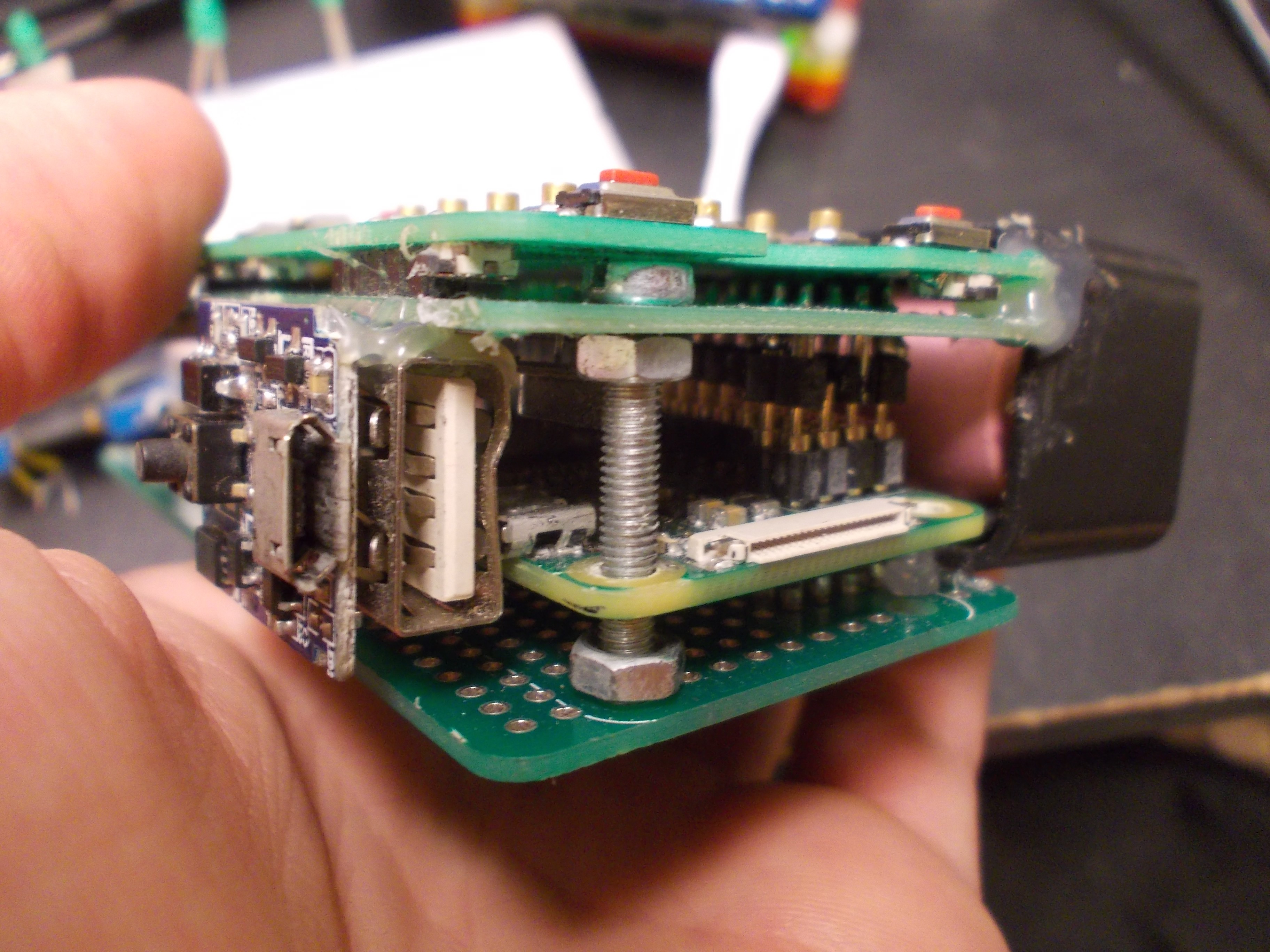

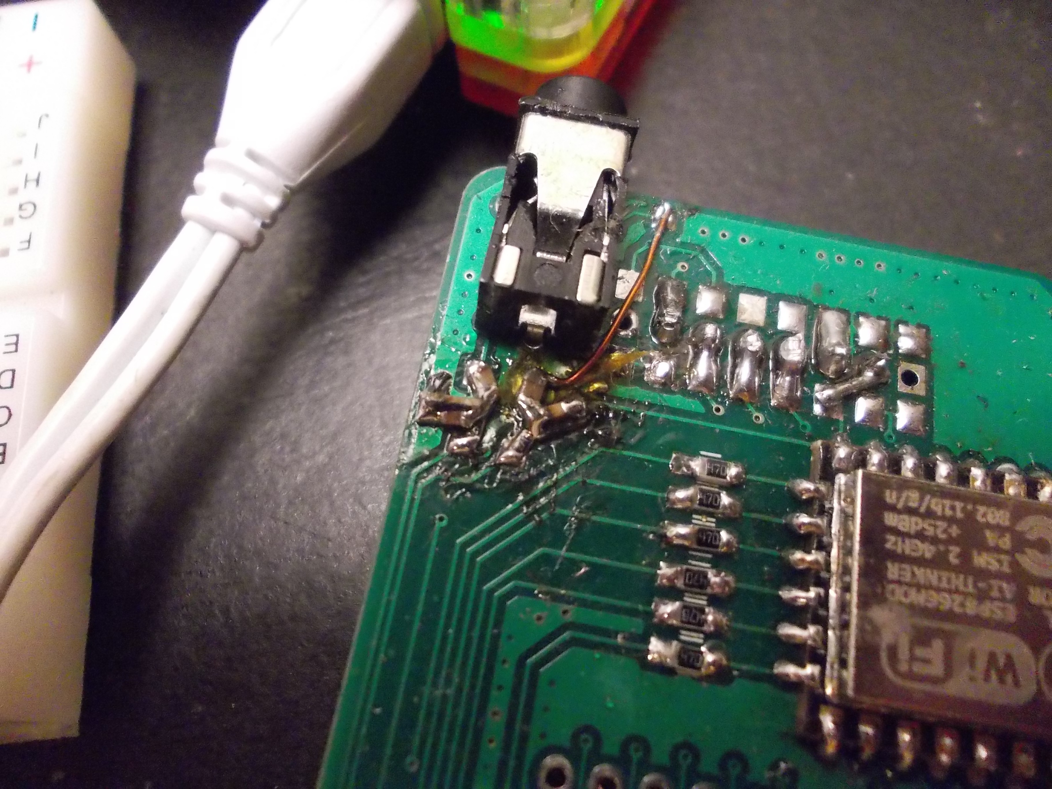
I wiped the tears off my face, desoldered the display and looked on the back of the PCB.
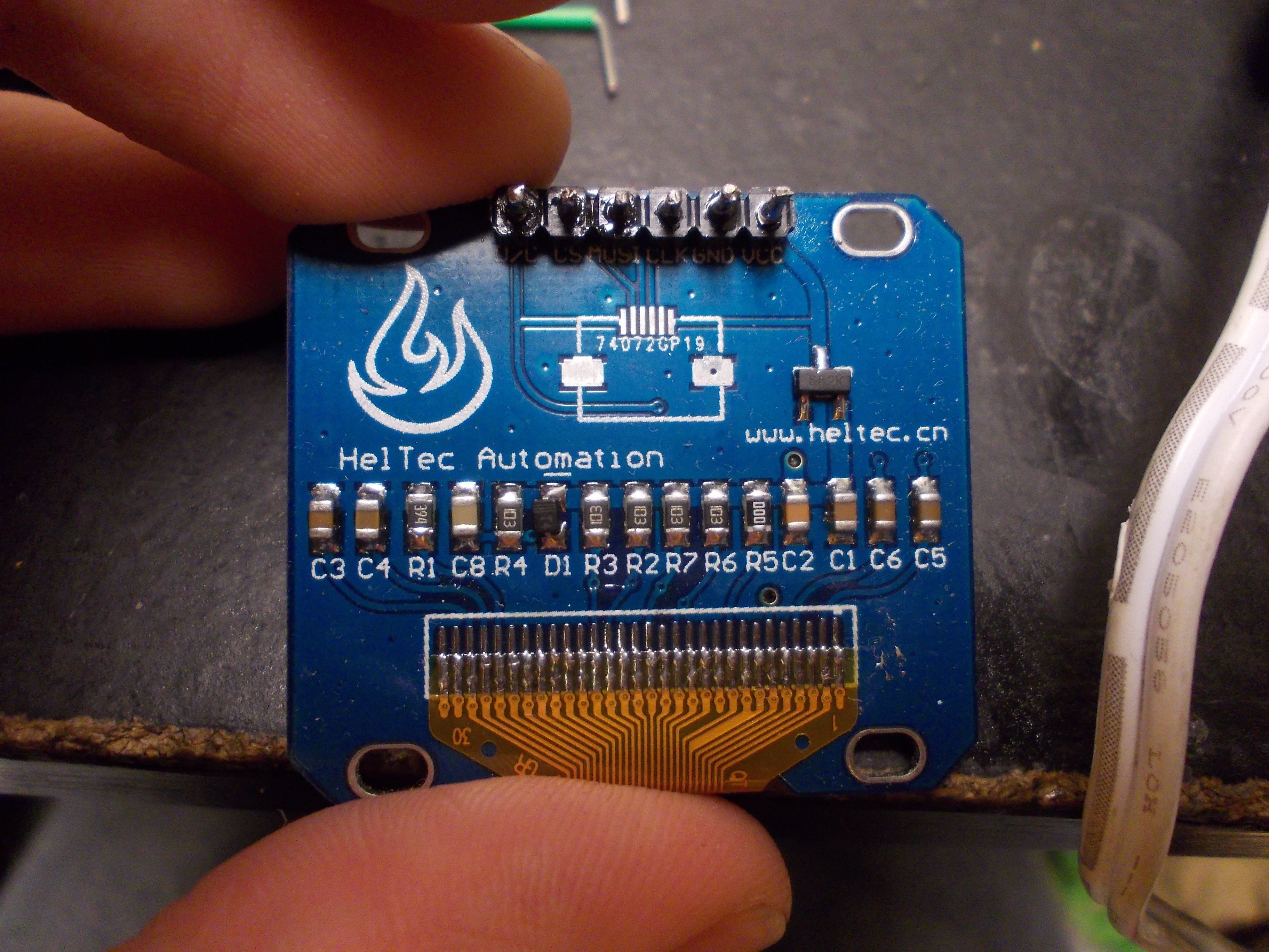
What would it be? Where does the RST signal go? On the first glance, nowhere. On the second glance, though...
Now, pretty much the only display-related trouble left is figuring out the importance of a voltage regulator on the display breakouts. In theory, the displays should be OK with 3.3V, which is currently the voltage available on the headers - but I know that at least one display behaved in a weird way after removing the regulator and shorting its VIN to VOUT.
This is how a big ZeroPhone trouble finally ends. This is not the end of "problems to be solved ASAP", though - there's this mysterious noise in the GSM audio lines, and I swear it wasn't there on the beta boards... To be continued.
Also, I still have to make a video, at least a short one. However, I'm quite sleepy by now so this will have to do.
Discussions
Become a Hackaday.io Member
Create an account to leave a comment. Already have an account? Log In.
Great news! Thats an epic bit of hacking, and a really good writeup :-D
It seems breakouts are the new lottery :-/
Are you sure? yes | no
This is even more unfortunate for a project that's based on breakouts =D But I'm trying to keep it under control.
Are you sure? yes | no
So glad to see this project continues! I know it's probably been asked a million times, but is there an estimated time of when crowd funding can start? I'm super excited to get one of these.
Are you sure? yes | no
It's a valid question, and the reason it's been asked a million times is because I've been postponing the date for a long time now =( On Monday, I'll start shipping prototypes, but it seems that I'll really need new display boards, so it seems that most prototypes will be delayed by this.
Are you sure? yes | no
I'll excitedly continue to check back daily then! (just read the software log, super excited to try it out!) going to get the pycli running on my pi later. Then I can try making some apps! Thank you for being so quick to respond!
Are you sure? yes | no
"5 days of response time" I wouldn't call it "quick to respond", and I'm sorry for this delay - for some reason, I didn't get a notification for your message, as I don't receive them for many comments on this project or project logs. I do look for comments manually, but for some reason I missed this one =(
Are you sure? yes | no
Still quicker than some correspondence I attempted with other projects! So no worries. You're busy.
Are you sure? yes | no
FML, no notification again. I'll go open a bug report about this, it's driving me nuts.
Are you sure? yes | no
Fritzing can do curved lines without any problem!
https://644db4de3505c40a0444-327723bce298e3ff5813fb42baeefbaa.ssl.cf1.rackcdn.com/6e21c4ac25430682b86fb8be9971d274.png
Are you sure? yes | no
At this rate, it's going to be weird to have 10+ boards designed in KiCad, and a single one - in Fritzing, but I'll look into it - if KiCad doesn't actually have any way to draw/import curves, and if I'll be bored enough =)
Are you sure? yes | no