-
1Step 1
Instructions are under construction
Sorry for any inconvenience =) It takes time to make them as good as I want them to be.
-
2Source the PCBs
You can use OSHPark, DirtyPCBs, Elecrow or some other PCB manufacturing service to order PCBs. Grab the latest release from GitHub, order the PCBs and wait for them to arrive! More detailed instructions are available here.
-
3Source the components
The full list of components (with links to places where to source them) is still being compiled here. Meanwhile, you can use this Google doc as a reference - I'm also making my calculations for larger-scale manufacturing runs of ZeroPhones there.
-
4Assemble the 18650 holder board
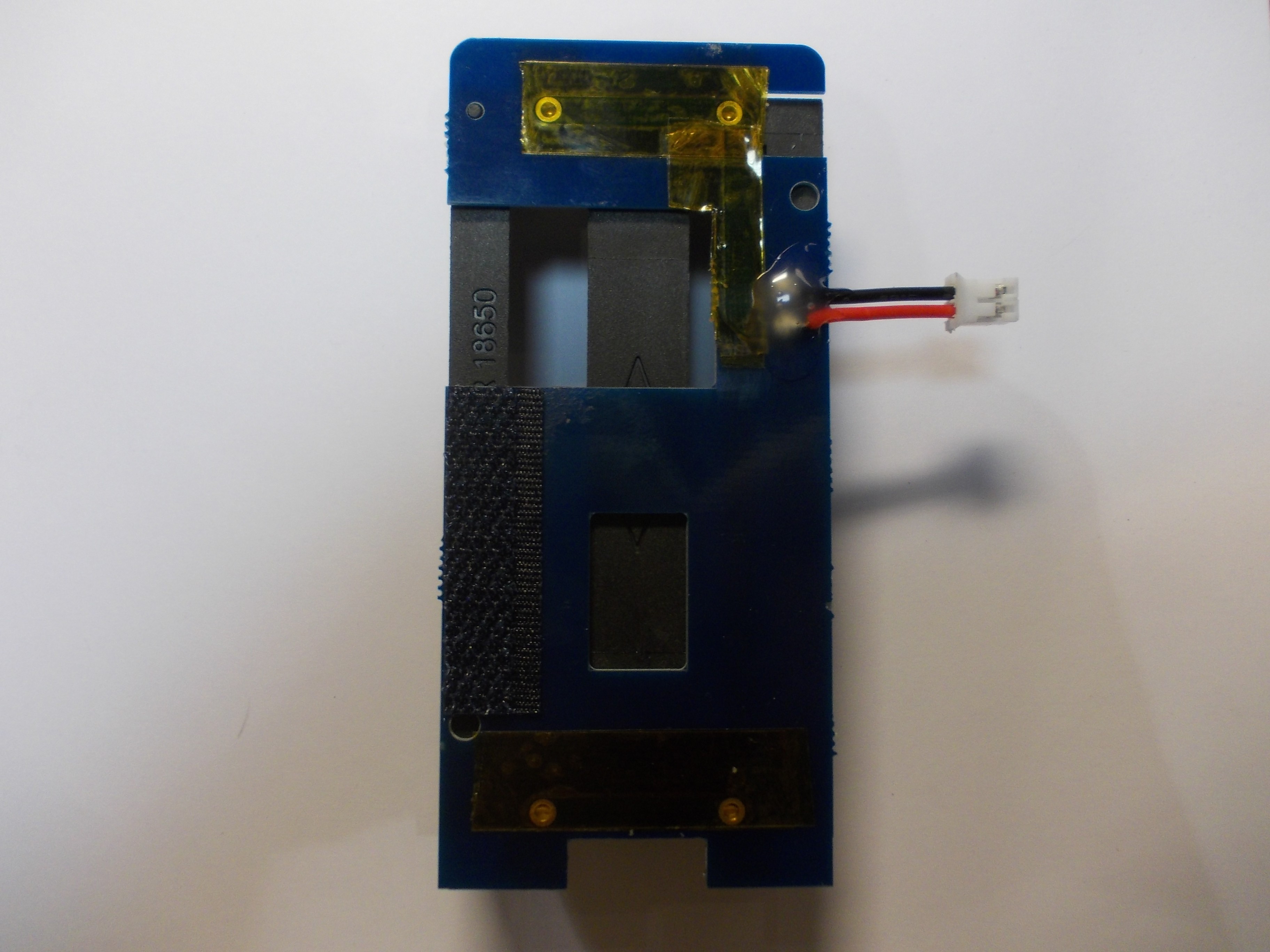
This board is the easiest to assemble by far, you just have to solder the 18650 holder to the PCB, then solder a 2-pin JST-PH pigtail (that is, connector on a wire) onto the holder and attach a strip of Velcro. For Gamma revision, you also need to apply a bunch of fixes - apply Kapton tape and some hot glue.
Preparations - PCB (with holder already soldered on), JST pigtail, Velcro strips, Kapton tape and hot glue
JST pigtail soldered on
Hot glue and Velcro applied, Gamma board Kapton tape fix made
-
5Assemble the keypad
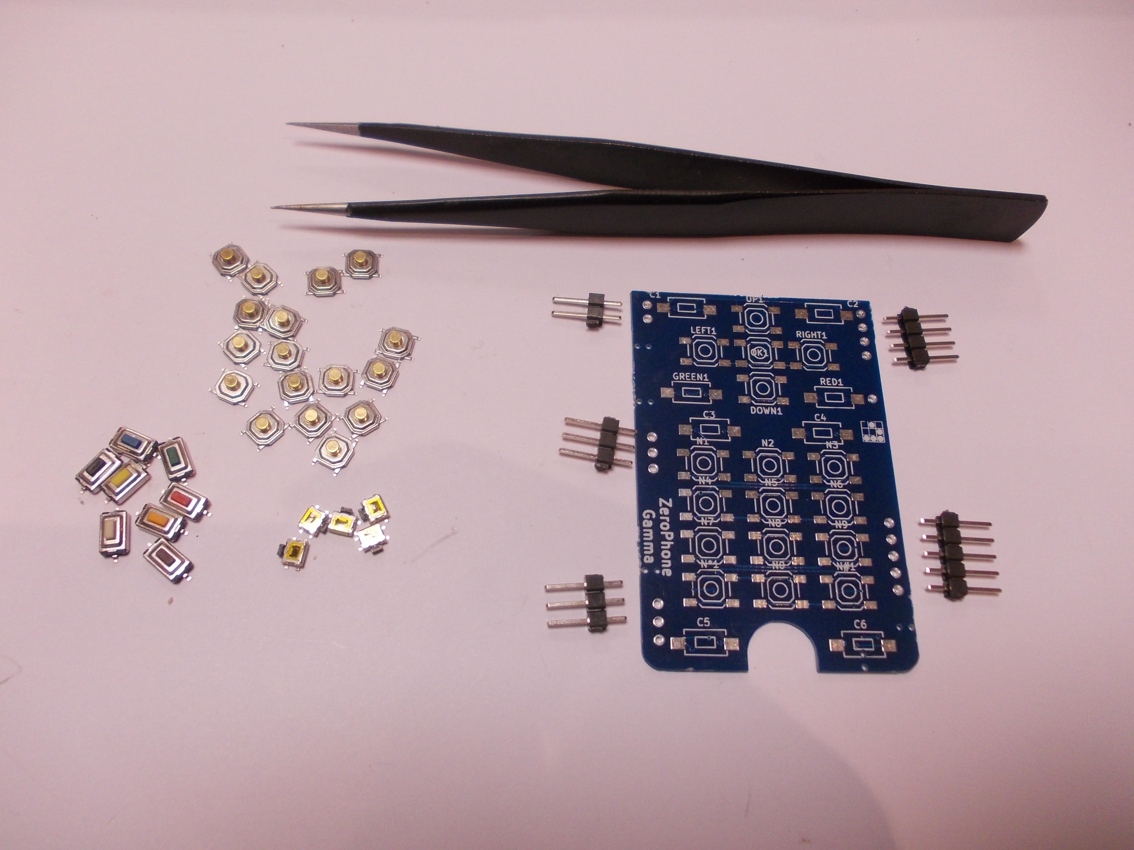
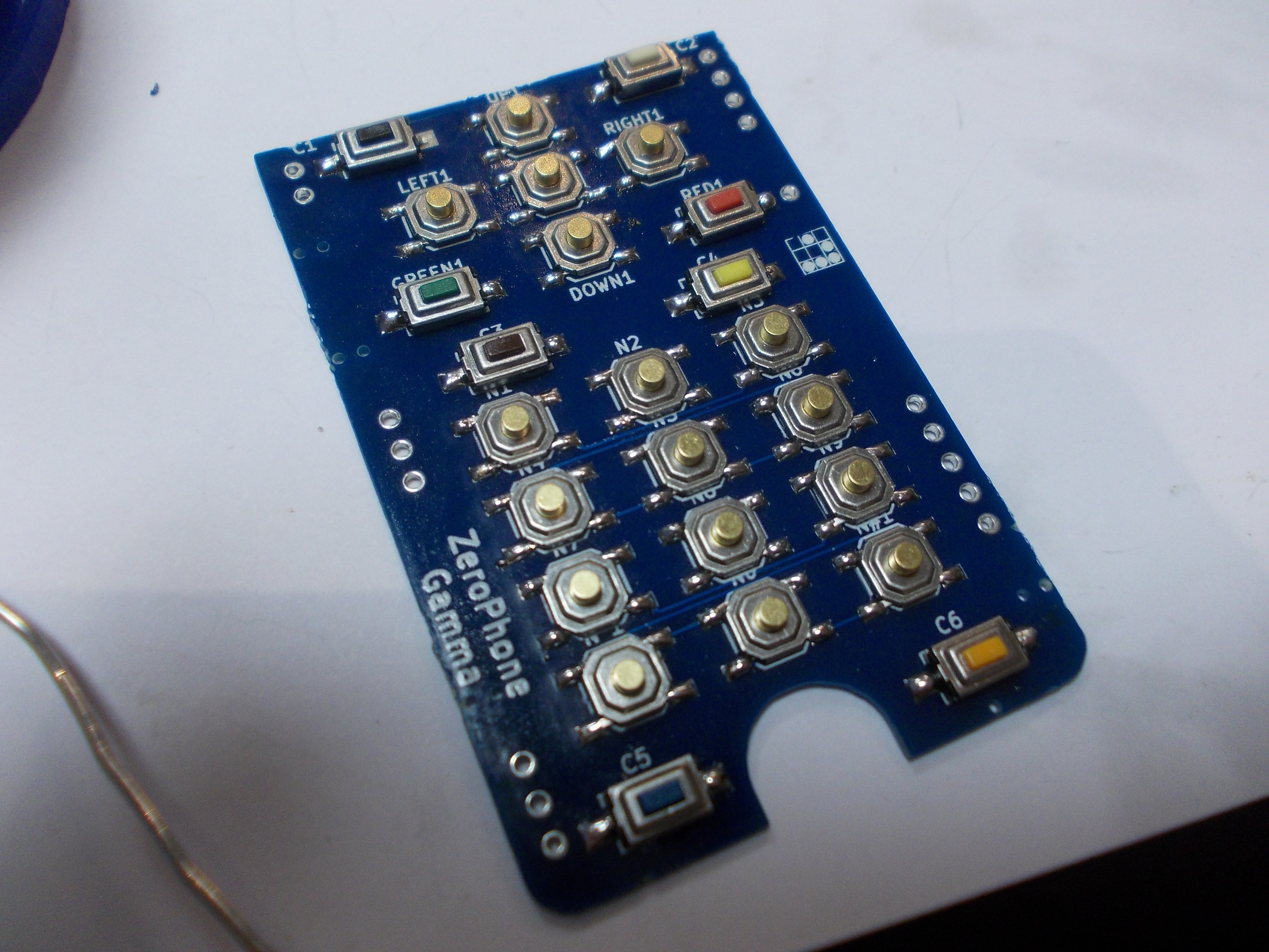
This is the second easiest-to-assemble part of the ZeroPhone, it only has SMD components and failing to assemble it won't do any electrical damage to the phone (at worst, keypad won't work at all, I'll list things to beware of down below). Prepare components - the PCB, 17x 4-pin buttons, 8x 2-pin buttons and 5x side buttons, as well as a pair of sharp tweezers (and, of course, a soldering iron with solder):
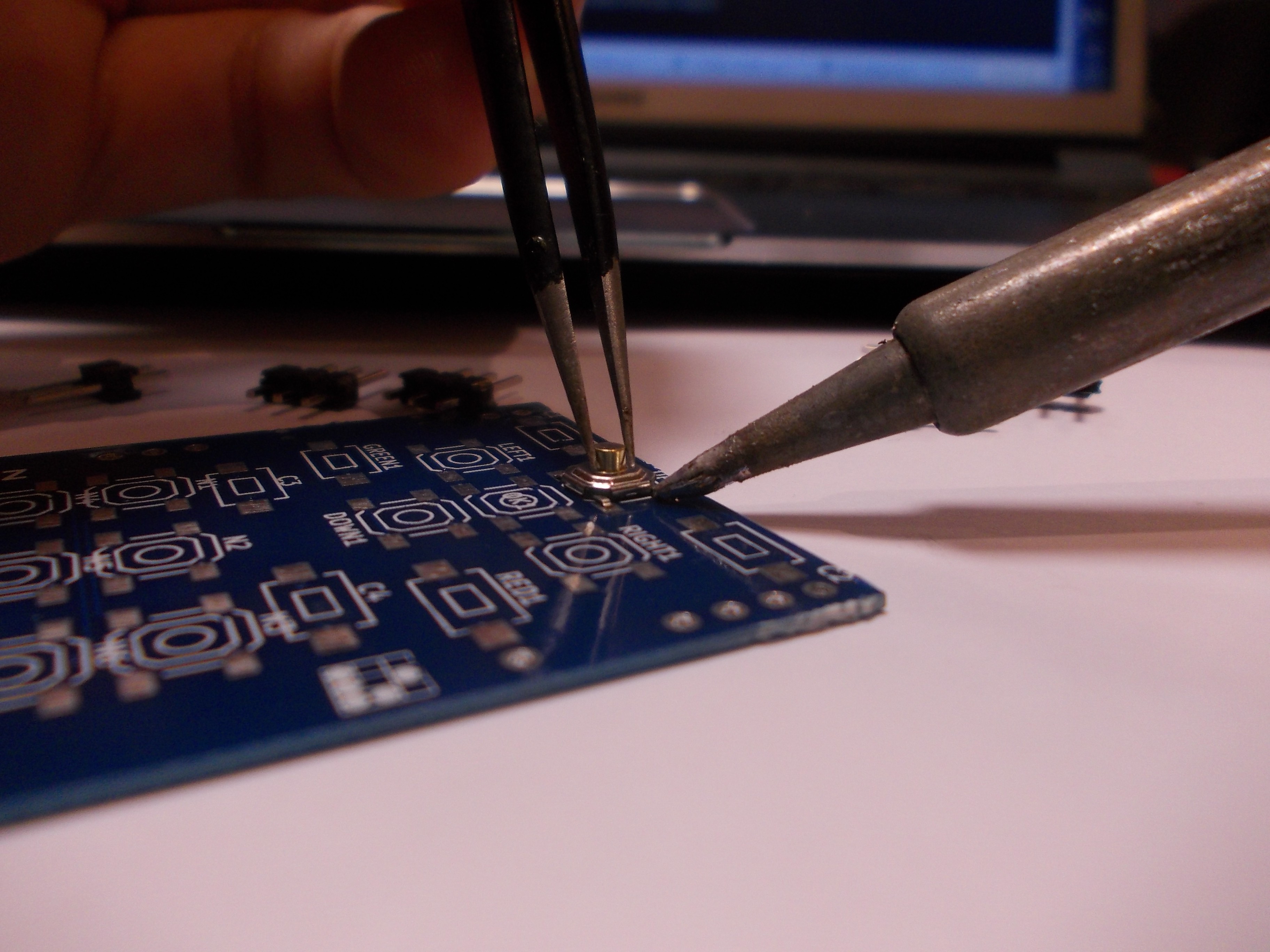
Start by soldering 4-pin buttons. Put solder on one of the pads of the button footprint:
While still heating the solder with the soldering iron, take a 4-pin button with tweezers, insert it into the solder and position it just right.
Solder all the remaining pins:
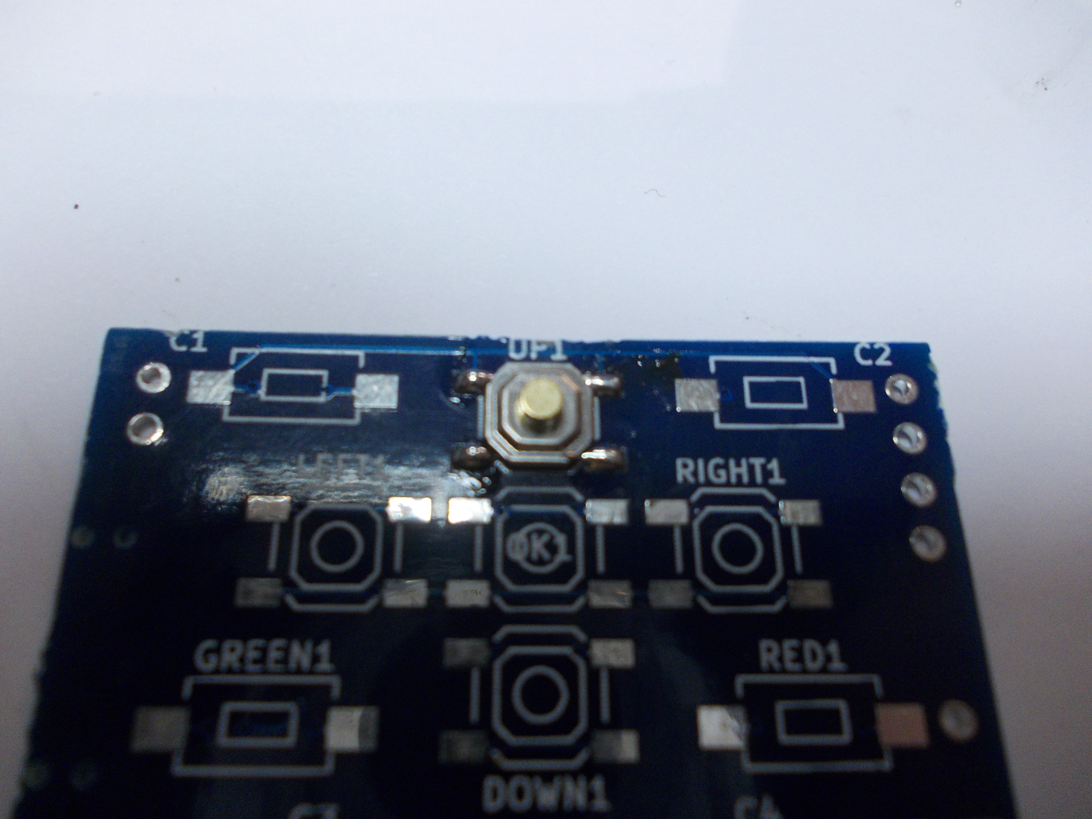
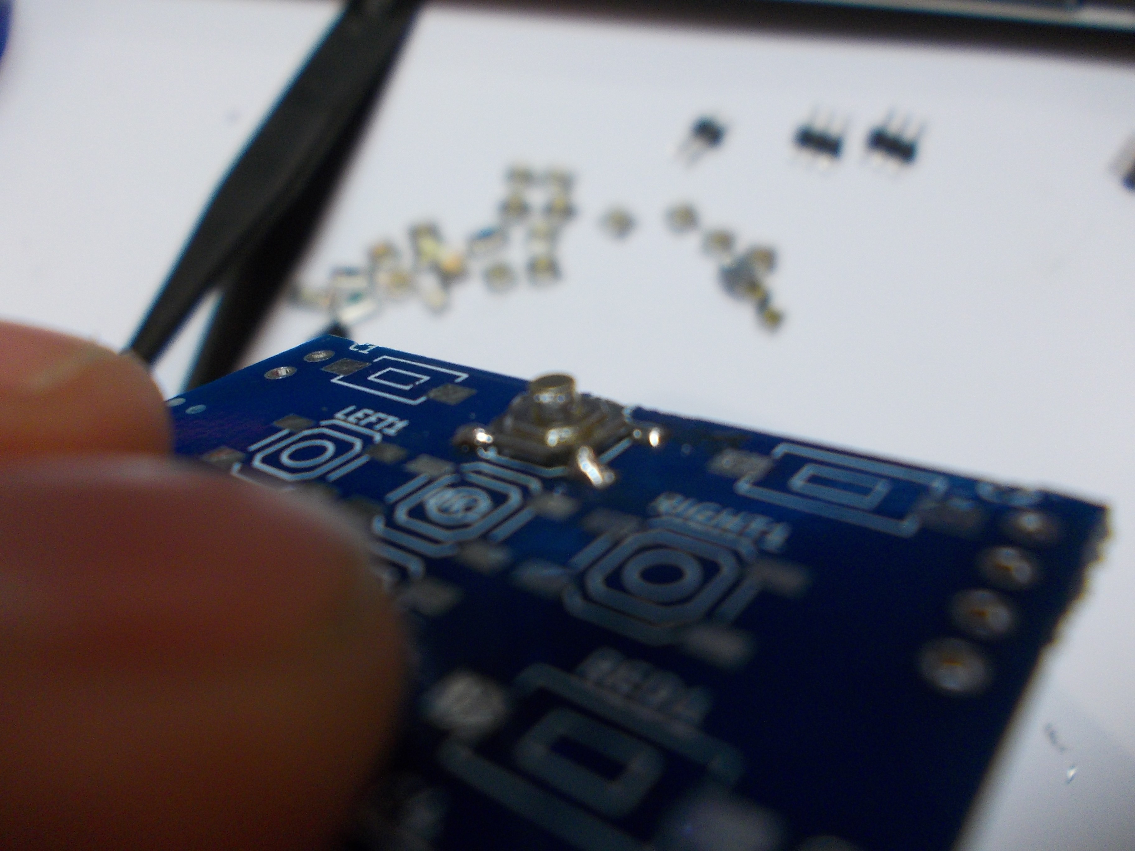
This is how not to solder the button:
Note excessive solder on the closest pin, bridging the pin to the button's metal shield, as well as some solder on the golden-ish part of the button, those both are not advised.
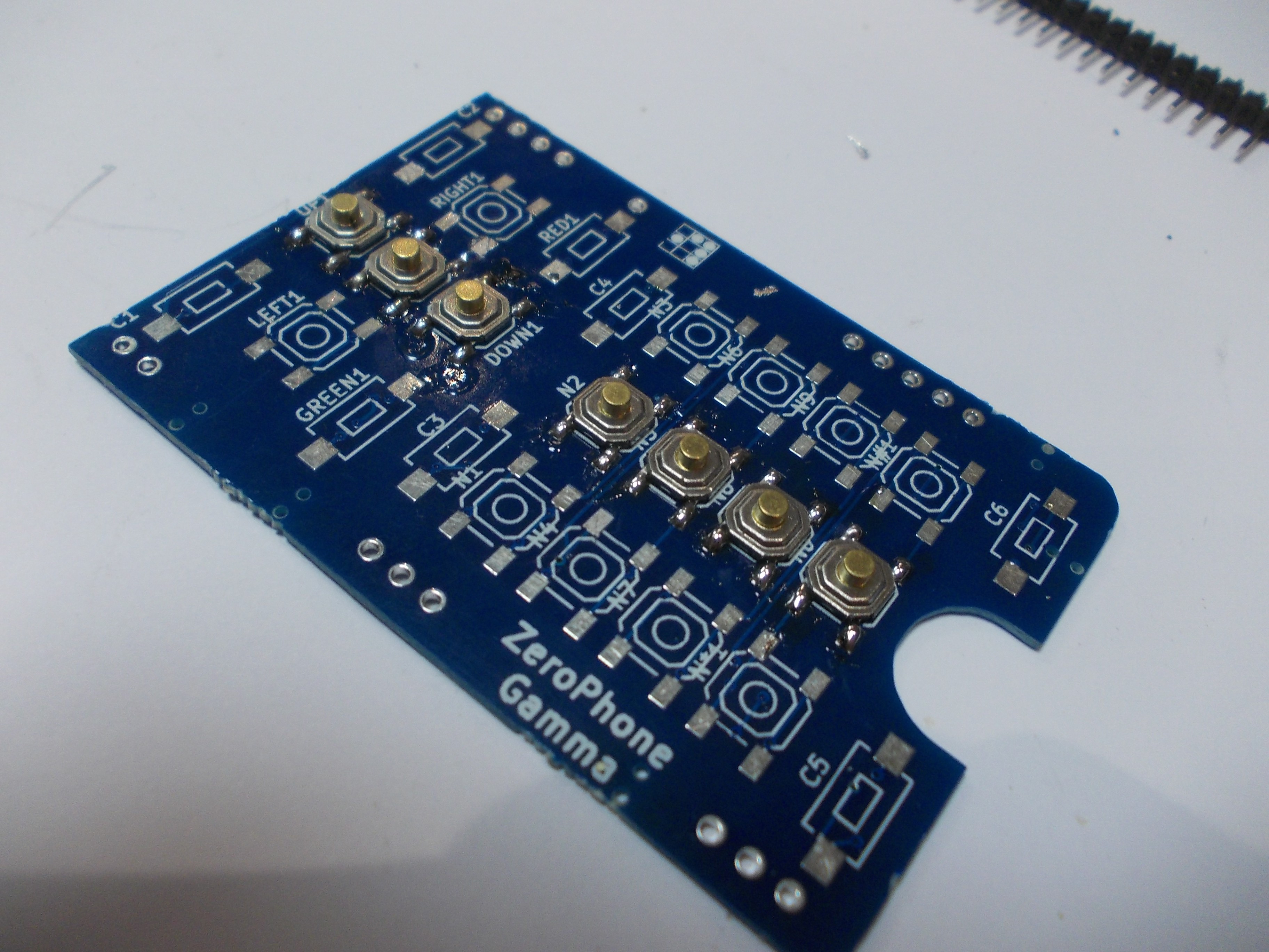
Solder the center row:
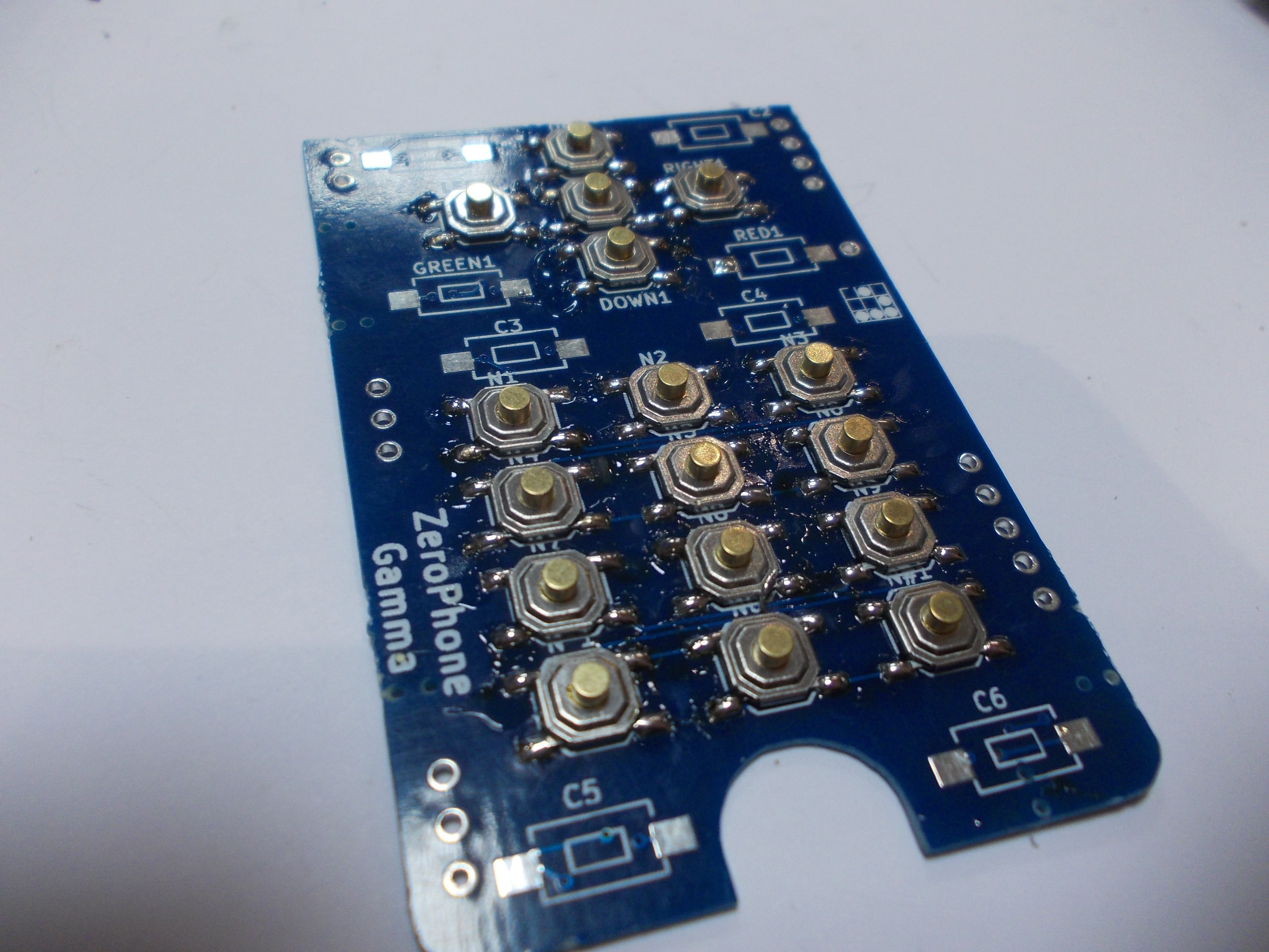
Solder the remaining rows:
Now you can solder the 2-pin buttons. The idea is the same - put solder on one pin, put the button on the board so that one pin is soldered to the board, then solder the second pin.
Note the 2-pin button color scheme - if you have colored buttons, this is the scheme that I advise you to follow. Otherwise, go wild! =) I went over the board with a flux cleaner spray, that's why no flux is visible.
Now, we need to flip the board and solder side buttons on. If your buttons have small alignment pins on the bottom of the board, soldering them will be slightly easier. If the buttons' bottom side is flat, I suggest you use a little bit of superglue to attach the buttons to the board, before soldering them. In my case, buttons didn't have alignment pins, so I used a toothpick to place small droplets of superglue on the board, then put the buttons on the board and adjusted them before the glue would set:
Now, onto soldering them. Do it one pin at a time, and be careful not to solder two adjacent pins - otherwise, the button will electrically look like it's always pressed, effectively blocking any other keys from being detected.
-
6Assemble the front board
-
7Assemble the back board
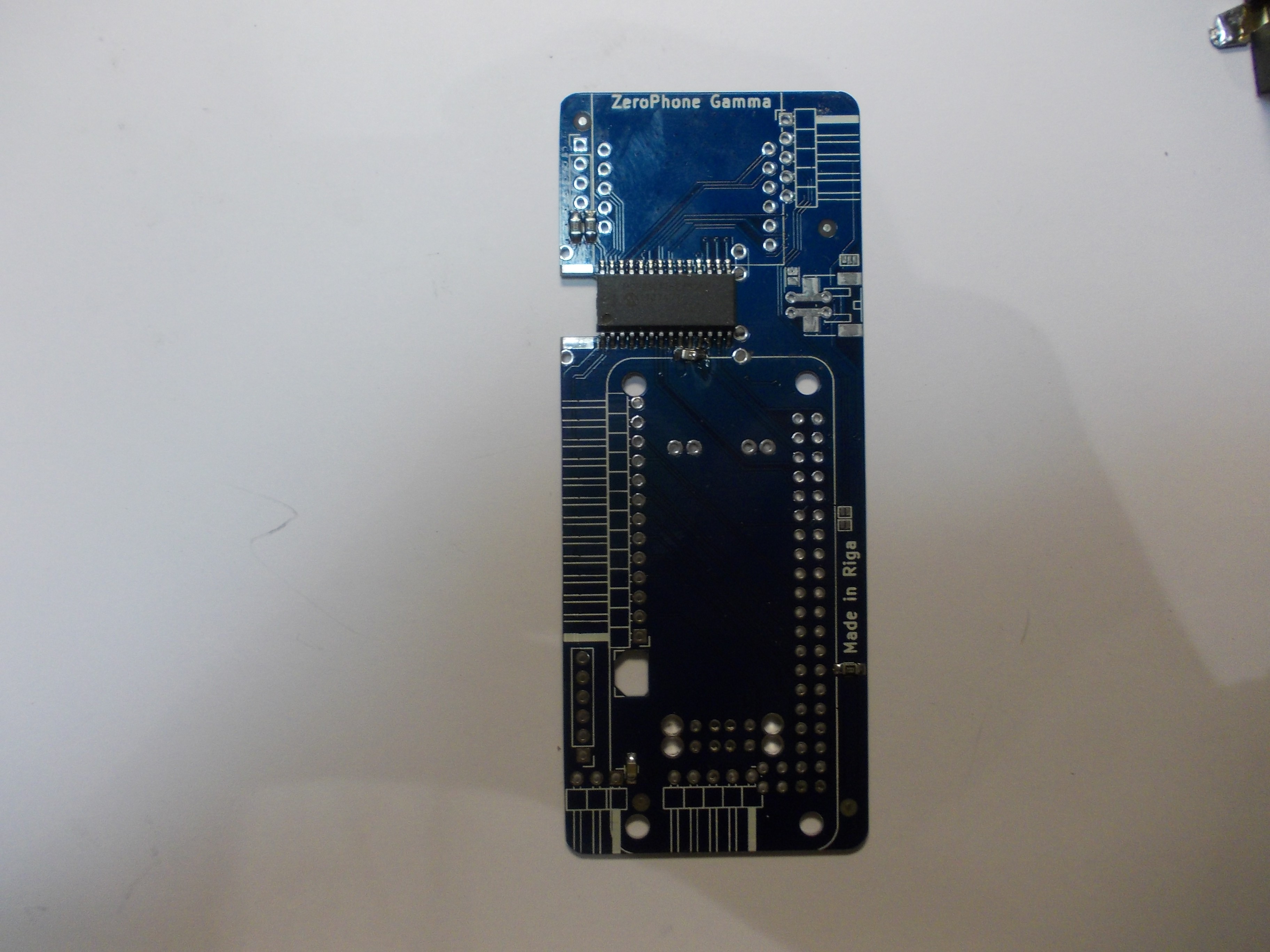
The back board has a MCP23017 IO expander with some resistors and capacitors on one side, and mostly power management circuitry on other side.
Front side with SMD components mounted
-
8Flash ATMega on the front board
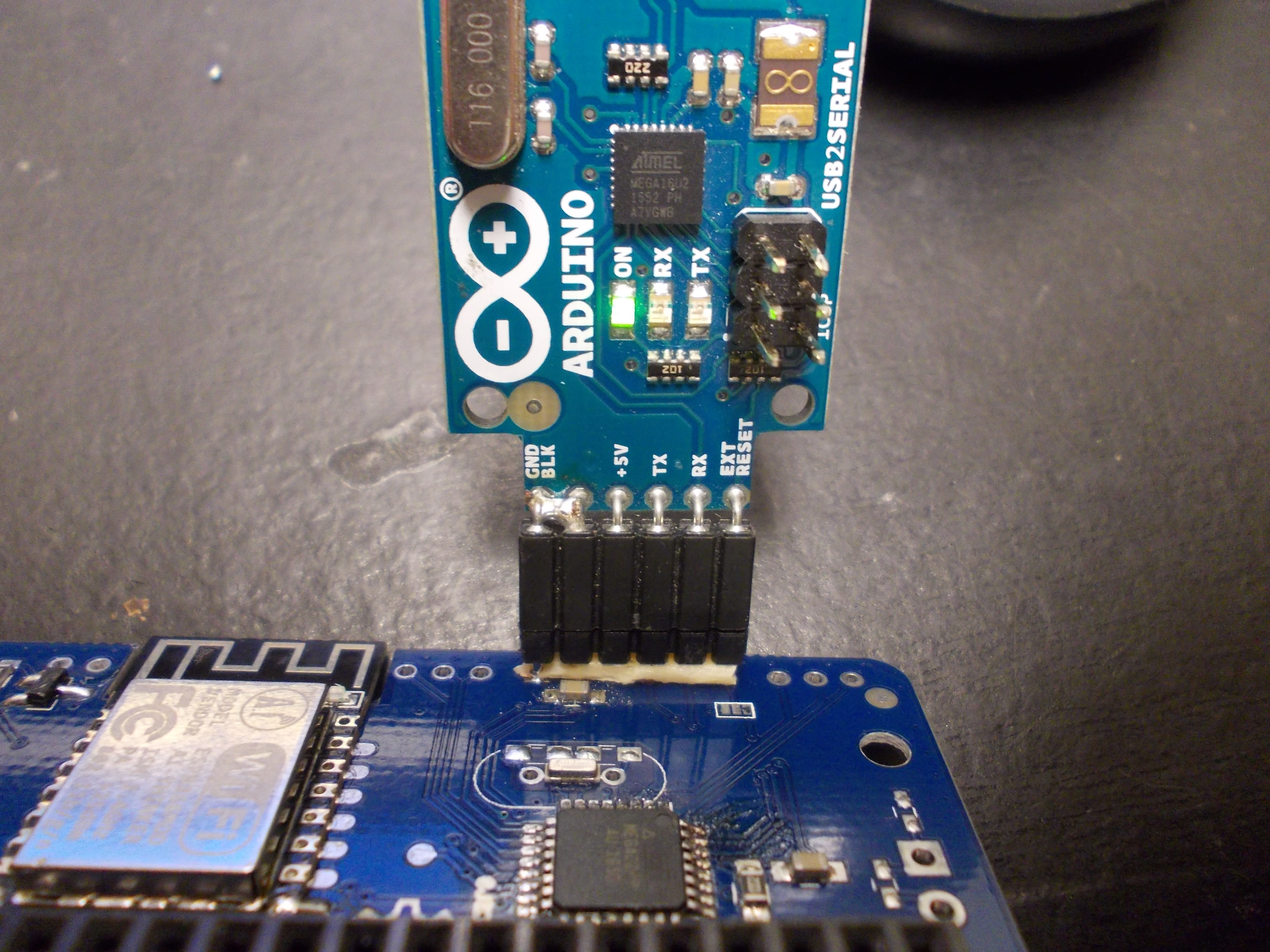
Use Arduino IDE and a USB-UART adapter (preferably, with the "FTDI" pinout, as it's going to be easier to use). Firmware is available here, use "Arduino Pro Mini, ATMega328P, 5V/16MHz" settings in the Arduino IDE settings and flash it. More detailed instructions and information on the ATMega functionality is being kept and maintained here.
-
9Solder the Pi Zero onto the back board
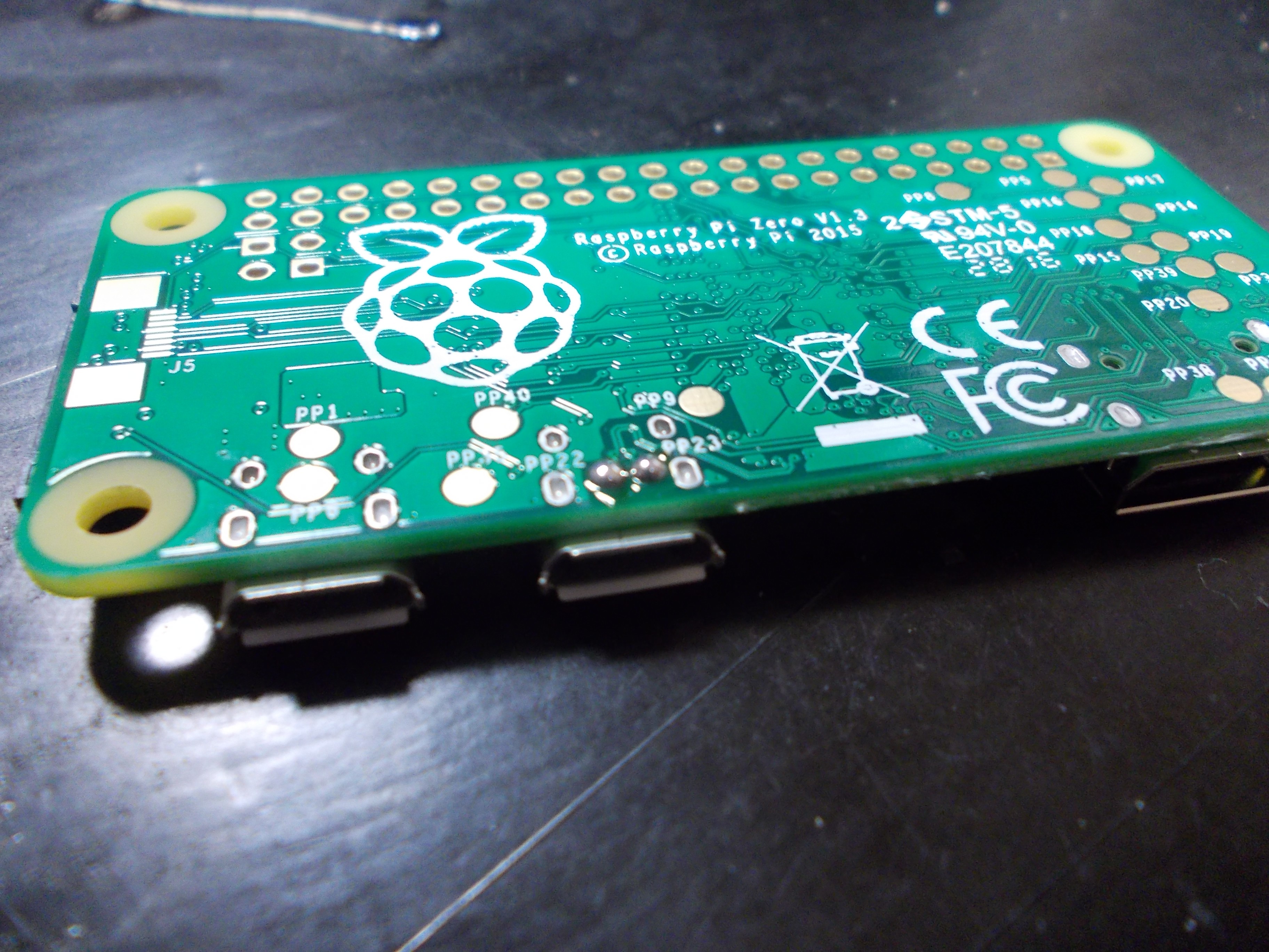
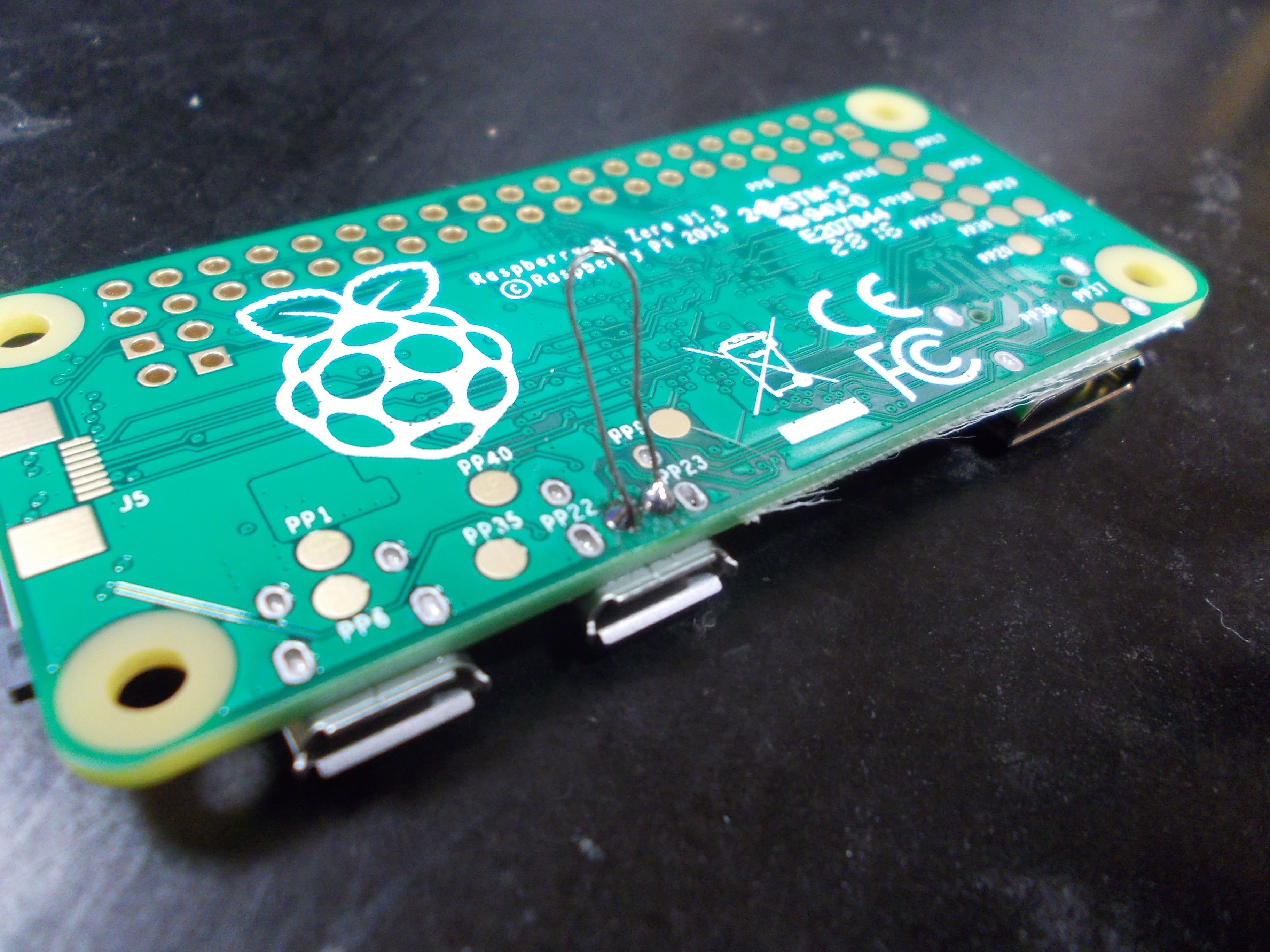
The Pi Zero has to be soldered onto the back board pin header. You also need to use small bits of wire to attach the Pi Zero USB data line testpoints to corresponding pads on the back board.
This is an almost-irreversible operation. Before you solder that, make sure you have soldered the full-sized USB port into place.
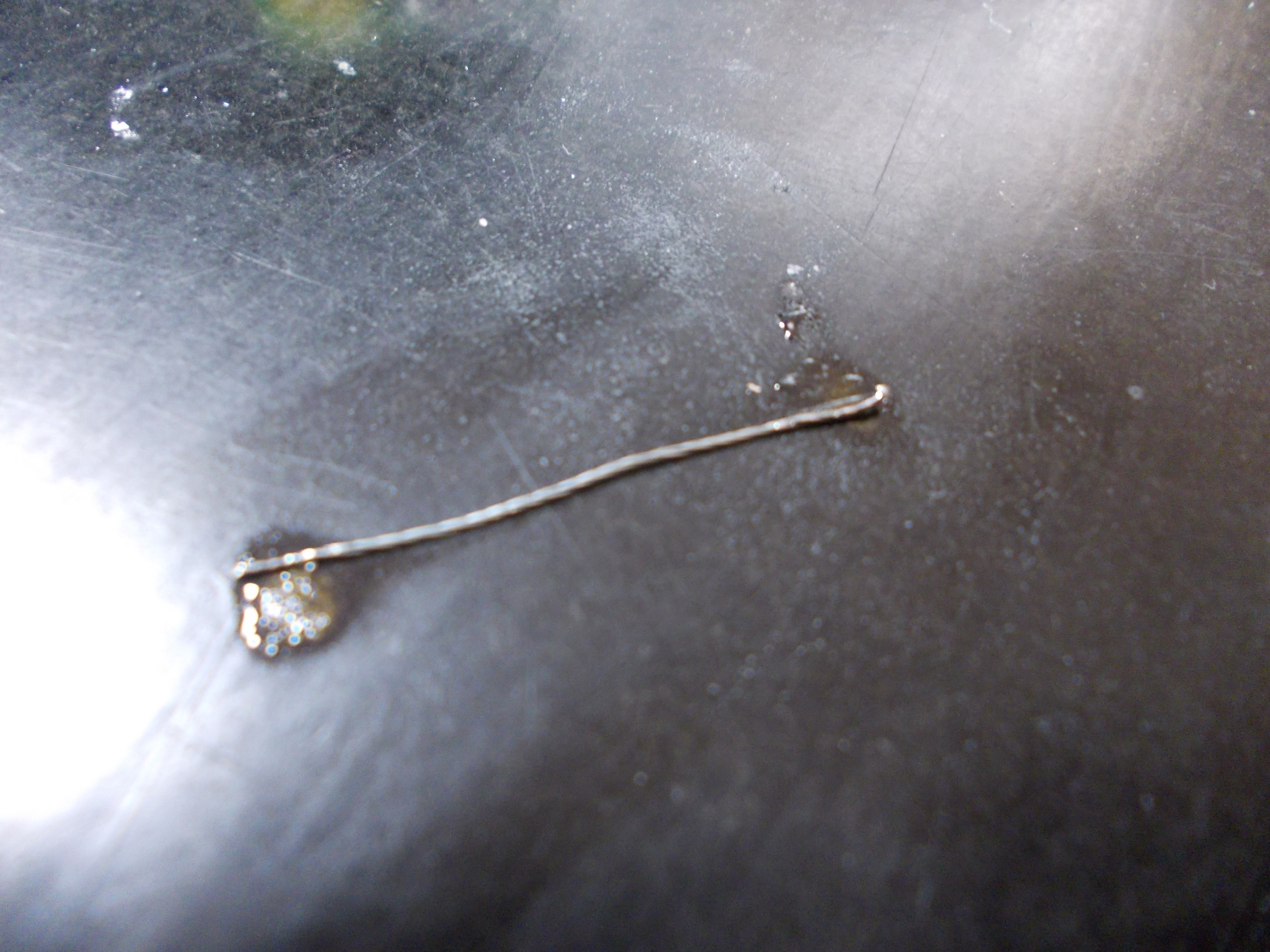
First, prepare a 2.5cm (~1in) piece of non-isolated multi-strand wire. Twist it, then tin it from both ends:
Add solder to the Pi Zero's USB data line testpoints:
Bend the wire in half, and solder it to the pads (taking care not to bridge anything to anything)
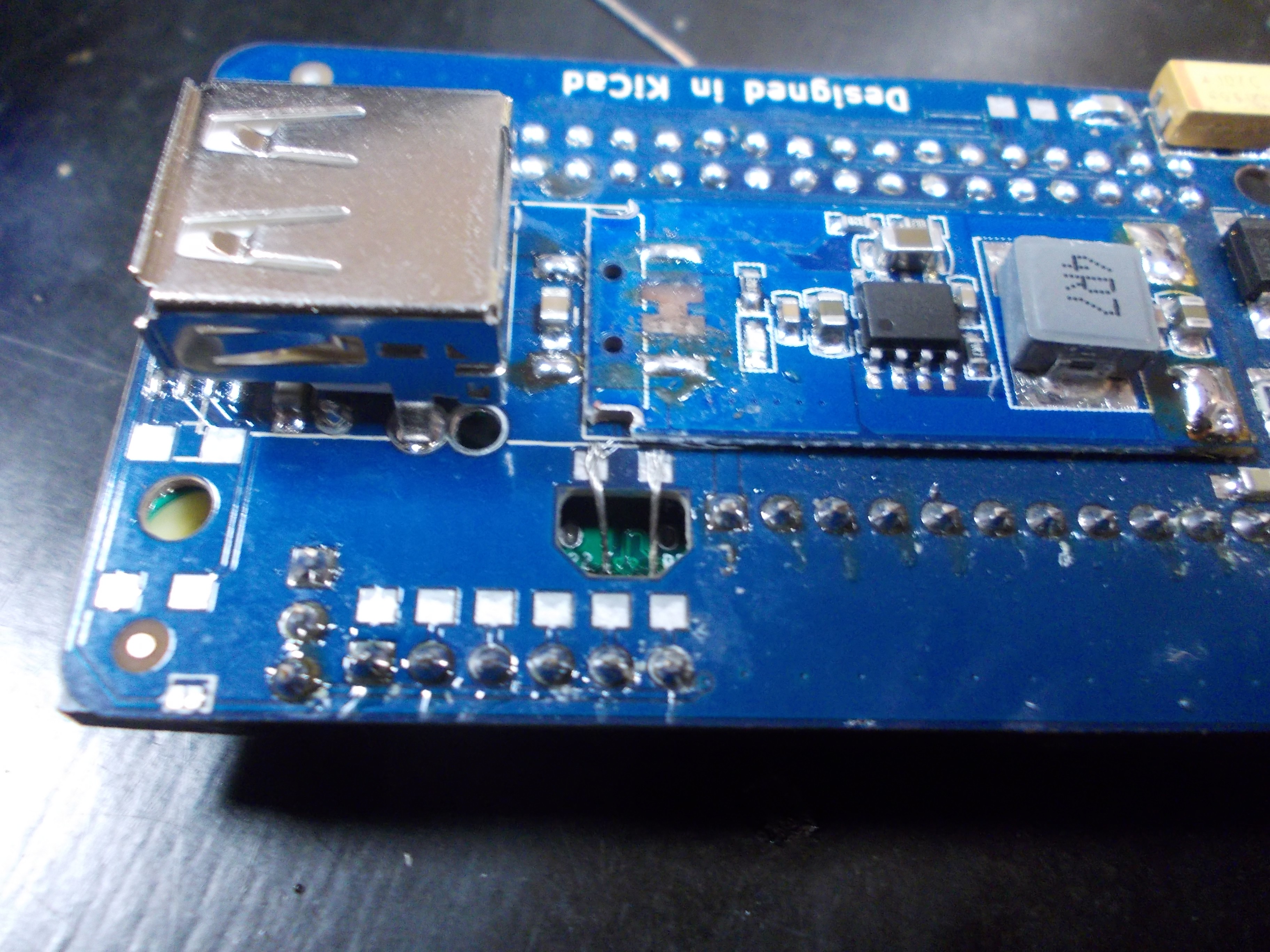
Now, seat the Pi Zero onto the 40-pin header on the back board - taking care so that the wire we just soldered goes through the opening in the board. After the Pi Zero is seated on the connector (no gap between Pi Zero PCB and pin header plastic), bend the wire onto the back board, cut it in half and solder to the pads:
TODO: replace this picture with a picture of wire that's soldered.
Now, onto soldering the Pi Zero to the pin header. -
10Go through the assembly checklist
Check if you have missed some not-so-straightforward steps - the checklist is available on ZeroPhone Wiki
ZeroPhone - a Raspberry Pi smartphone
Pi Zero-based open-source mobile phone (that you can assemble for 50$ in parts)
 Arya
Arya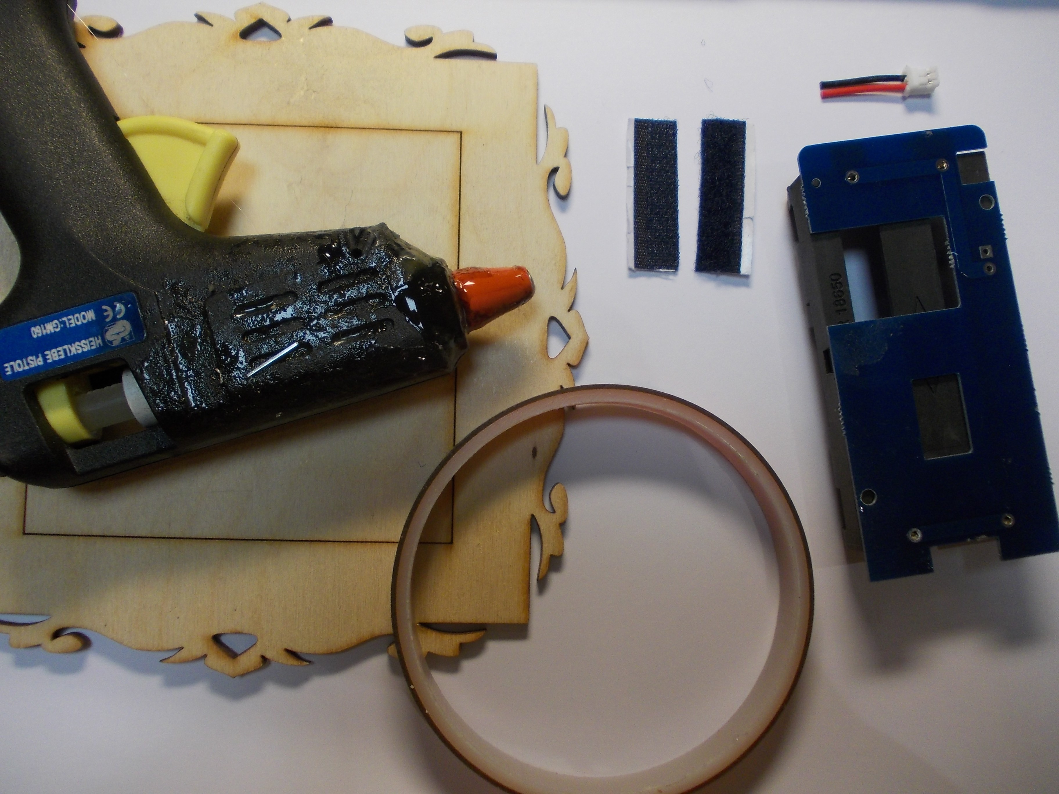


Discussions
Become a Hackaday.io Member
Create an account to leave a comment. Already have an account? Log In.