Arya
Arya-
A guide on powering Pi Zero directly from LiIon batteries
10/23/2017 at 05:10 • 3 commentsAt the project's beginning, when I was writing the "Features" section in the project's description, last entry was "Tons of Pi Zero-related hacks that were discovered along the way, that I'll share with you as the project goes =)". I didn't actually get to sharing any of them in 9 months' time (also because there actually weren't many I found noteworthy), so last time I was editing the project's description, I just removed that line. Now, I've been reading through hackaday.com/blog, as usual (to be exact, through email notifications that I receive for each post that comes up there - highly recommend subscribing to those). Pi Zero-based projects get there every now and then, part of them are portable projects, most of those use LiIon batteries for power - for example, SegaPi Zero does - check it out!
The small problem that I see with portable Pi Zero-based projects is - they all use a step-up, to get 5V for powering Pi Zero. When I started designing ZeroPhone hardware, one of the biggest problems was: how to avoid the stepup? Board space was not plentiful (still isn't), I don't know of many 5V-suitable step-ups that actually work well and are easy to source, and sourcing yet another part would be a PITA. Now I'm sure that, in many "Portable Pi Zero" cases, having a step-up is unnecessary, and ZeroPhone experience so far proves it.
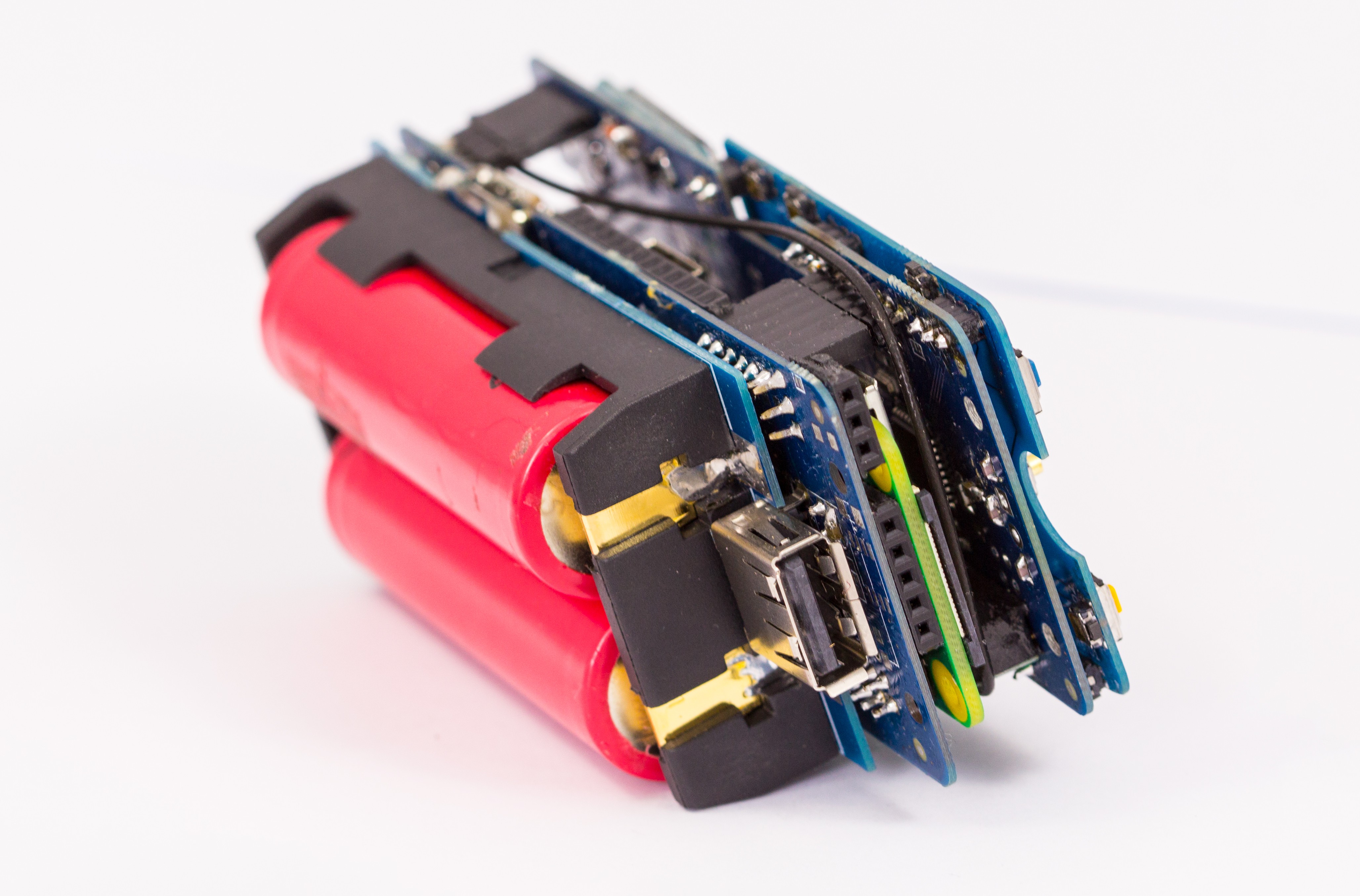
In ZeroPhone, Pi Zero is powered from a Lithium-Ion battery directly (so, instead of suggested 5V, it's getting 3.3V-4.2V). Does it work? Hell yeah it does! It works reliably, saving power, money and board space. What follows is a wall of text that describes why I went that way, and how's that supposed to work:
---------- more ----------![]()
One of the step-ups that I found to be highly unreliable in my previous projects
So, why even bother powering the Pi Zero directly from a LiIon battery?
- Powering the Pi Zero from a stepup is unnecessary waste of energy, due to the fact that it's doing "boost, then regulate down" conversion instead of just "regulate down" (the conversion losses are bigger). So, going without a stepup gives you more runtime for your project.
- Cheap step-ups tend to be unreliable. You can source a more expensive one, from Adafruit/Sparkfun, but you might as well use that money on something that'll be actually useful for your project.
- Stepups take up space in your project's case (in my case, a stepup would take up board space).
What are the disadvantages?
- You need to track the battery voltage. You do need that even when you're using a stepup, just that with a stepup it's easier to overlook (but also easier to run your battery beyond the safe limit).
- You'll still need a stepup if you need to power random USB devices.
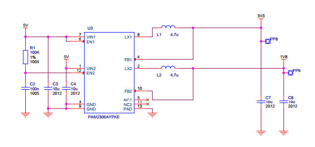
Here's where I started with this topic - people on Raspberry Pi forums reporting success with powering the Pi Zero from as low as 3.3V. Let's take a look on the small part of Pi Zero W schematics, to be exact, a small part of a small part of the schematic:
![]()
5V on the left is what we get from, usually, the USB port, and 3.3V & 1.8V on the right are what's used for the CPU, peripherals and whatever else needs to be powered on the Pi Zero board. We need to see if we can replace the 5V with 3.3V-4.2V, and to see if that's possible, we need to know where 5V is used. So, the parts where 5V appears are:
- The PAM2306 regulator (wired according to the schematic right above)
- USB ports - in case of a Pi Zero, there are no protections or anything, the USB ports' VCC is wired in parallel.
- 40-pin header - pins 2 and 4, also in parallel
- HDMI port's VCC - through a diode (to avoid backpowering the Pi through the HDMI port)
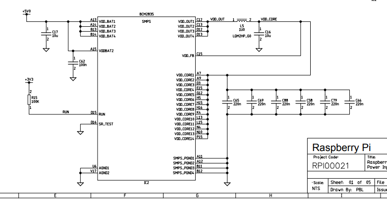
- BCM2835 built-in voltage regulator:
![]()
The built-in regulator uses the 5V to generate the VDD_CORE voltage, to power the CPU itself.
Again, LiIon voltage is going to range from 3V to 4.2V. Which of the mentioned components are OK with this, and which aren't?
- The PAM2306 claims Vin range to be from 5.5V to 2.5V. However, the version of the regulator, evidently, is a fixed-output version, and one of the outputs is 3.3V - as PAM2306 doesn't have boost capabilities and isn't even wired to be able to boost anything, What's the minimum voltage we have to feed it, then? Well, this graph from the datasheet says it's tested to work with 3.5V while fixed on 3.3V:
![]()
With this, and the fact that regulator claims to have 100% duty cycle operation capability, let's say that the resulting range is 3.4V-4.2V - well within operational capacity of most rechargeable LiIon batteries (not talking about LiFePO4 or other, even more exotic breeds) - Are USB devices compatible with 3.4V-4.2V? Even though USB specification defines USB VCC as voltage in 4.75-5.25 range (IIRC), some devices don't actually need that much - many feed 5V into a linear (sometimes switching) regulator that drops the voltage to 3.3V, or even less. I've had success with running CP2012-based USB-UART dongles, USB-ISP dongles, even WiPi dongles and some other devices (like flash drives and USB hubs) from 3.4V-4.2V. I definitely wouldn't attempt to charge a smartphone from that, though - that's where those 5V are actually necessary (since battery chargers in phones aren't designed to operate from LiIon voltage, they'd need a step-up to keep up with the 4.2V CV step requirement). tl;dr - here's where having a step-up is actually economical. I also wouldn't power a USB 3G modem, for instance.
- 40-pin header on Pi Zero is blocked by ZeroPhone boards, from both sides, so you can't actually plug a HAT that could require 5V ;-) On both front and back boards, there are no devices that actually require 5V - most of them either work from 3.3V, or from VBAT.
- HDMI port's VCC is designed to power an EDID EEPROM (so that the monitor's characteristics can be read from it), or a HDMI-to-whatever adapter. Well, by now, I'm sure that none of EEPROMs used in more-or-less modern monitors actually require 5V - the 5V-only EEPROMs seem to have become obsolete, since it's not exactly economical to produce them, as compared to EEPROMs that accept a wide range of input voltage. Anyway, it's a requirement mismatch, and I don't have an opinion on the adapters - they might as well require 5V and not a volt less.
- I don't remember anymore where, but I've read, either in some Raspberry Pi documentation that has since vanished, or on Raspberry Pi forums, that the VDD_BAT accepts a wide range of voltages, including the LiIon battery range (which makes sense, since the voltage it has to output is pretty low, about, what, 1V?)
So, there are problems with powering USB devices, and possible problems with HDMI. There are, actually, more problems:
- It's bad practice to power something from a LiIon battery while the battery's being charged - that can lead to the charging cycle never finishing properly, essentially, whatever you're powering will be powered from the charger, and it's going to be, at best, confused about that. I've heard something about potential for the battery to be overcharged, I don't understand the topic enough to confirm that's a possible consequence, but that is something to be on the lookout for =)
- There has to be a low-voltage cutoff, so that. at a certain point, if the charger is not connected and the battery voltage is too low, everything's powered down until battery gets back up again. The charging&protection circuit has a 2.5V cutoff, but that's not good enough - the Pi Zero will go into a cyclic reboot long before that.
- If you're powering a Pi Zero from LiIon voltage, you need to take care to not connect 5V in parallel, that is, if a battery is connected to the 40-pin header of a Pi Zero, do not connect a MicroUSB cable with 5V to the Pi Zero's USB ports! Best case is battery's protection circuit will trip (that's why I highly recommend you have one). ZeroPhone solves this by making MicroUSB ports on the Pi Zero inaccessible, hiding them behind a 6-pin header that connects the front and the back boards.
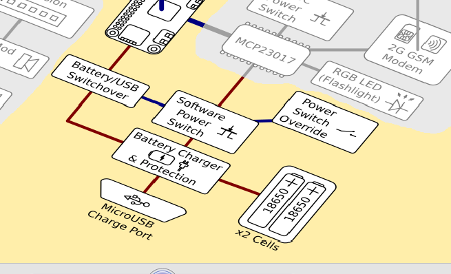
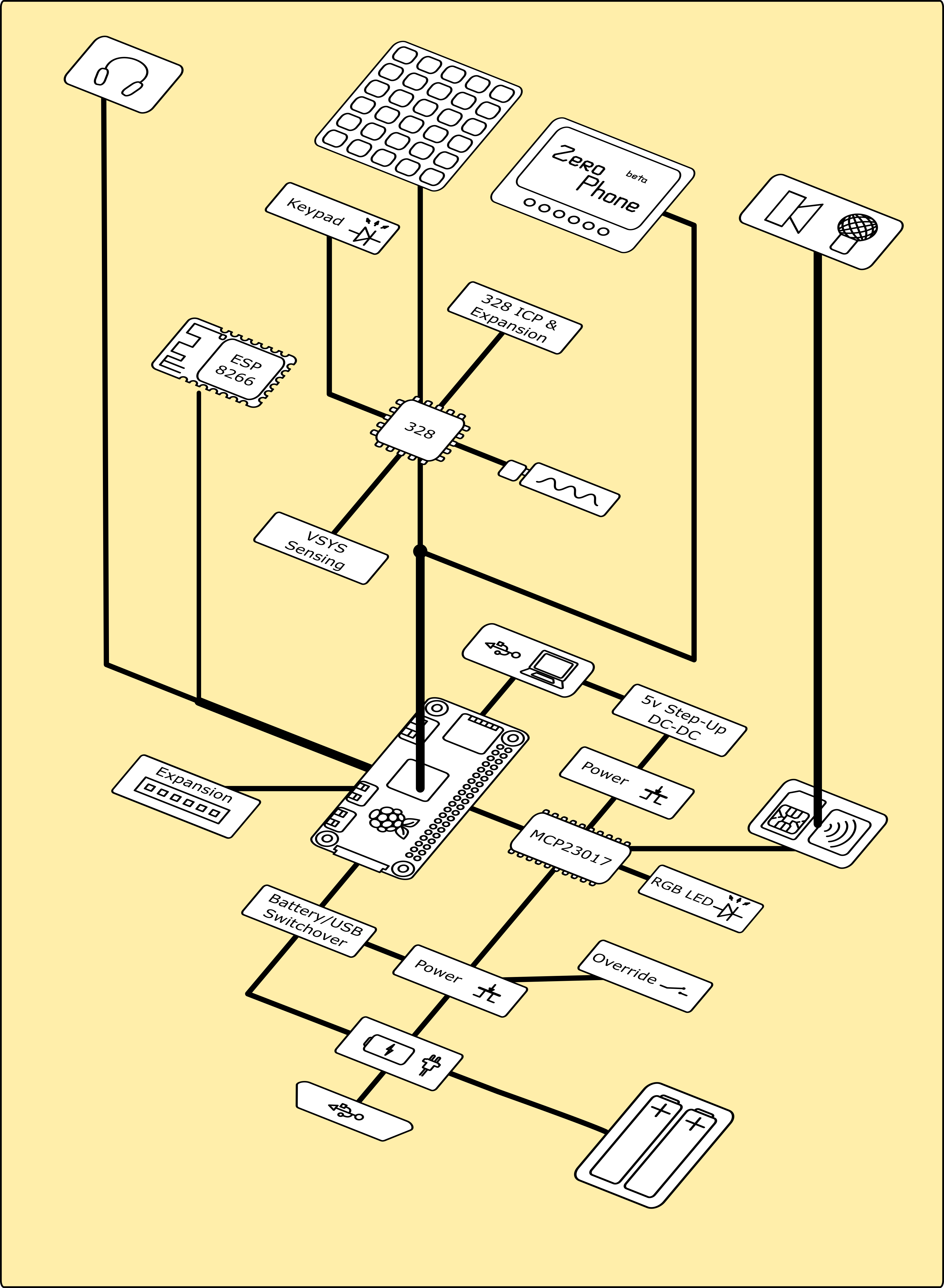
How does ZeroPhone solve those problems? What else is necessary to make it all work as good as it has to? Let's take a look at the block diagram:
![]()
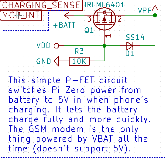
There are two operational modes to take into account - when a ZeroPhone is powered from LiIon batteries, and when it's connected to a charger. When it's connected to charger, it's in our best interests not to continue powering everything from the battery, as the battery won't be able to charge fully. So, the "battery/USB switchover" block is responsible for that. Here's how it looks:
![]()
Here's an in-depth description of this circuit. Effectively, when a 5V charger is connected to a MicroUSB port, the Pi Zero is actually powered from 5V, so it doesn't load the battery and it can charge in peace (the GSM modem, on the other part, is connected straight to VBAT, since it can't tolerate 5V - haven't yet found a good way to solve that, but the charger still seems to be able to finish charging the battery just fine). This also works as a workaround for any possible problems with HDMI power - if a device requires 5V, you can work around it by plugging ZeroPhone into a charger, so that the HDMI voltage will rise to 5V.
Now, about "software power switch" block - it shuts off the battery from the system, and it's controlled from the Pi Zero. Its main function is to work as a low-voltage cutoff. The idea is simple - on Linux side, there's a daemon that tracks the battery voltage (which is available from two sources - from the GSM modem and from the ATMega, which has system voltage available through a resistor divider). There's no software support for this switch yet, though - the daemon capable of such a thing is not yet written, main reasons for it are: 1) the GSM stack is not yet integrated into ZeroPhone software, so there isn't yet a consistent way to expose GSM modem's battery voltage tracking capabilities 2) ATMega firmware doesn't yet expose the battery voltage 3) there has to be some kind of UI to notify the user, and pyLCI doesn't even have notification support yet, not to mention a home screen, where you could show the battery icon. However, we'll get there eventually =)
Now, about powering USB devices - that's where a step-up is, unfortunately, indispensable in a setup like this:
![]()
However, on ZeroPhone it's only enabled when it's actually necessary to have 5V for powering something, due to the fact its power is controlled from software, due to the power switch - so energy still isn't wasted =)
So, you don't want to read all this, and you want to power your Pi Zero in a more efficient way, so that you get that additional hour or two of runtime. What are the requirements, and what are my suggestions?
- Make sure you're using a protected battery, or have a protection circuit on the charger breakout you're using. If it has separate contacts for OUT+/OUT- and B+/B-, you likely do have a protection circuit on the charger breakout, otherwise, use a separate protection circuit, or one built into your battery (if it has one). This requirement applies even if you're not using a stepup.
- Use a switchover circuit, it'll allow your battery to charge fully, and will help in case there are problems with HDMI. It's simple - one P-channel MOSFET (I use IRLML6401), one Schottky diode (I use SS14, I guess 1N5819 would work too) and one resistor (10k works well for me). If you don't want to source parts and solder it yourself, I have 20 small boards with those components already on, that I can sell for $5/each (excuse me while I go and open a Tindie store with these, but feel free to PM me to order one or two before it's set up =) ).
- If you have an accessible USB port, that's where you actually need to have a step-up. Otherwise, you need to make sure that the USB devices you're powering is compatible with this voltage internally (though, worst case is, it just won't work).
- Make sure to not connect cables with 5V on them to MicroUSB ports if a LiIon battery is connected to the 40-pin header, and vice-versa.
I guess this is why I haven't done this writeup before - because of all the text I had to write to make this article as good as I wanted it to be. Regardless, I do hope this helps to creators out there, those who want to make Raspberry Pi-powered portable devices, just like I do =)
-
Low-key project state: Hackaday Prize video, cases!
10/21/2017 at 12:48 • 5 commentsJust made a video for the Hackaday Prize. Right now I'm too sleepy to talk about it, especially given that I accidentally the whole script, so I had to rewrite it 10 hours before, and some photos came to me at the last moment possible =(
Recently, I made a "How I use my ZeroPhone" worklog. It was really easy to write for me, I shared it on Reddit, got a lot of positive responses and some really good questions. Those questions prompted me to write two more worklogs - "Why ZeroPhone ships with 18650 batteries" and "Making ZeroPhone work as an actual phone". The first one was easy to write - the second one was noticeably harder =) Anyway, stay tuned for the next part of "How I use my ZeroPhone" - I hope it's going to be as easy to write as the first part!
Now, about project's contributors. @Ninjalicious has the first design of a ZeroPhone case!
![]() ---------- more ----------
---------- more ----------
It needs more work and testing, and we need to clean up files before we can publish them, but it already works as a case! Now, it does underline the ZeroPhone problem - it's really thick =D So, even though, as I mentioned, I can't use pouch cells as a default option, I will have to do more research on this and make sure it's an option that's reasonably accessible for people that don't have huge pockets.![]()
-
Making ZeroPhone work as an actual phone
10/20/2017 at 21:15 • 2 commentsOne of the most important factors that can contribute to a project falling into obscurity is - does it work as well for calls/SMS/data connections as a real phone would? Right now, it doesn't, and it's immensely important it does. I want to make it a point to have the GSM part, both in hardware and software, stable, and make it one of ZeroPhone project's promises. It's pretty much a pre-crowdfunding priority - that is, until I know it's possible to solve it without changing the project in some major way, I don't feel safe launching the crowdfunding. What's the plan?
[TODO: insert photo/gif of current phone UI]
First of all, the 2G modem works with ZeroPhone. I can send AT commands through the serial port to initiate or accept calls, as well as receive or send SMS. Apart from some bugs in the modem's firmware and an issue with the microphone noise (only affects current revision of PCBs), the hardware is accessible and working - but, obviously, you can't use the terminal to call others on a daily basis, and PDU encoding of messages is not that easy to decode by just looking at it =D Now, it needs GSM backend software to be usable.
---------- more ----------Well, it turns out that writing a decent GSM backend is hard. I have already attempted doing it, when I was still working on beta boards - as a result, pyLCI has a small UI for making calls and receiving calls, and the backend for it. Writing a working base meant accounting for a lot of special cases, however - modem doesn't respond to AT commands instantly, you need to track its states, properly route URCs (info messages that can come from the modem at any moment, such as "OH MY GOD UNDERVOLTAGE") and handle them. All of that involves having at least one more monitor connected, with the modem's AT command documentation open on it, and Ctrl+F-ing a lot through English where you'd need a thesaurus to find anything, since you can't rely on the translator having picked the obvious term for the function you're looking for (and not going for the least obvious one, and misspelling it to in a way that makes your eyes bleed).
I implemented URC handling (and limited processing), and all was going well. But then, when it comes to, say, SMS handling, it all needs an SMS storage system, with a separate API, provisions for adding various hooks, as well as decent input UI elements for editing SMS (basically, writing text editor logic in Python - doable, but not as simple). A contributor was going to implement this, but then I assessed the situation and decided that telephony is one of the last parts that would ever be have to be written from scratch. For example, what about GSM data? Whatever GSM backend is used, when GSM data mode is enabled, the GSM backend needs to create a network connection, while still keeping track of when the connection is broken (from either modem or user side), so that it can resume handling calls and SMS messages (you wouldn't like to miss a call or an SMS because tethering was enabled!). Can this be done in Python, in a way that is quick enough to not induce nostalgy about times when dialup was still widespread? It probably can... Well, with the most important parts written in C, that's my guess. So, the experimental UI and backend will remain there - but only for testing purposes.
What about existing backends?
Most useful link (that, for some reason, I only found recently) is going to be the description of telephony stack that Jolla uses, and the most interesting from all of that is ofono. I've actually seen ofono mentioned in Hackernews comments about ZeroPhone, even back in January/February, so I've tried it back then, and couldn't launch it - the documentation for a "start from scratch" situation just wasn't there. However, I've subscribed to their mailing list, have been reading conversations and patches, and I'd like to think that I started understanding how it works, and about ZeroPhone-relevant aspects of it =)
There is also ModemManager. Their documentation is much better than ofono's documentation is, but they're not actually that well-suited for, say, handling voice calls - networking seems to be their stronger side. However, I'm still looking on its capabilities, as a backup plan - and reading their mailing list, of course.
I've asked a couple of questions on the ofono mailing list a couple of days before, and got answers that were more than satisfactory:
>>  Hi!
>>
>>  I'm interested in running ofono on a Raspberry Pi (BCM2835, 1GHz), connected to a SIM800 modem over UART (the stable Pi UART, not the MiniUART). I also have RST, DTR and RESET signals connected to the Pi, and for sound I'm using analog audio outputs and inputs of the modem. Basically, I'm talking about using ofono in ZeroPhone project - https://hackaday.io/project/19035 .
>>
>>  For now, I'm interested in 1) notifications about voice call status (not concerning audio for now, as it's handled in hardware) 2) SMS and MMS support 3) 2G data connections (whatever available connection types are on 2G networks) 4) USSD support. My questions are:
>>
>>  1) Is ofono going to be suitable for my needs? I'm more than OK with using DBus and rolling my own user interface to it.
It supports everything except MMS. That requires a separate MMS stack
and is out of scope for oFono. I don't know of any full-featured open
source MMS stacks, but I'm probably not paying enough attention. Maybe
someone here can give you pointers.
You can take a look at the (now undeveloped) mmsd project to see how the
MMS stack should interact with oFono:
https://git.kernel.org/pub/scm/network/ofono/mmsd.git/
>>  2) How do I run ofono from command-line and tell it to connect to a specific serial port and use a specific ofono driver?
You write a driver for it and since it is a serial port modem, use udev
rules to setup the TTY port accordingly. See doc/sim900-modem.txt for
an example. The device detection magic is inside plugins/udevng.c and
most modem drivers reside in plugins/*. See the plugins/sim900.c, it
may be close enough to the sim800 to get you started.
>>  3) Do you foresee any necessary changes to ofono? For example, need to make a sim800-specific driver?
The most likely answer is yes. All new modems integrated into oFono
required 'some' vendor/firmware specific handling. However, it is not
possible to answer that unless you have the modem control protocol
specifications in hand. If it is a standard AT command based modem,
then the changes should be minimal.
>>  4) I see that Sailfish phones are using ofono as the GSM backend. Did they upstream their changes, or do they have a fork?
They have a fork.
>>  5) I'm planning to work with SIM5320 modem in the future, and attempt using its USB connection. I know it creates multiple serial ports, and supports streaming audio over one of them. Does ofono come into play here, does it have some kind of provisions to convert this kind of audio input/output into actual sound devices under Linux, or is that usually handled by other software?
oFono does not handle the audio bits. We can take care of sending the
necessary AT commands to the device to configure the codec, etc. But
the actual audio processing belongs in your audio daemon. E.g.
PulseAudio or whatever.
--------------------------------
>>  Thank you, that was a great answer. I'll focus on one part for now:
>>
>>  Is it possible for me to run ofono from command-line, without involving udev? I'm asking this because, in my application, I'm using the UART as a debugging UART for first 30 seconds of phone's boot, then, if there's no activity (or other trigger set), I enable the GSM modem and run the GSM backend. Is there a reason why ofono is not capable to be run this way (provided it's not capable of this)? Is there a way I can just do the setup that udev would normally do, but manually? If so, where should I look for pointers - code, documentation or somewhere else? (doc/sim900-modem.txt? plugins/udevng.c?)
oFono can be started any time you wish. udev is just normally used to
detect the hardware. Either via probing the USB bus, or in the case of
serial devices via external configuration (e.g. udev rules). Without
udev oFono would not know what TTY corresponds to the modem. E.g. on
some platforms it may be ttyS0 and others it would be /dev/ttySAC0, or
whatever.
The oFono plugins / modem drivers are free to do anything they want. So
if you want to hardcode the behavior, that is fine. You can always
implement your own detection logic. For example plugins/phonesim.c uses
a config file, plugins/rildev.c uses getenv. The possibilities are endless.
udev is the preferred approach, other approaches might not be palatable
to upstream.
In terms of documentation or pointers, it really depends on your
hardware setup. If you have a traditional AT command based modem with a
multiplexer, then take a look at doc/calypso-modem.txt and
plugins/calypso.c. This is the modem used on the original Freerunner.
If you have multiplexing handled by the kernel, then the SIM900 docs /
plugin might be applicable.
So, now at least I have an idea on how to launch it. What's more, ofono even ships Python code examples! The plan is as follows:
- Make ofono run with a known-working modem, see if it's fully compliant to what ZeroPhone needs, determine requirements for mobile data support
- Write a driver for SIM800 (can be based off SIM900 driver which already exists for ofono)
- Write the pyLCI-side UI for calling
- Add SMS and call history storage - either use an existing one, or roll our own (only in case of fundamental incompatibility, and borrowing as much architectural decisions as possible)
- Add UI elements for SMS viewing and writing
- Add SMS support to ZeroPhone
- Work on mobile data support
- Work on hooks (allowing users to add features like automation, blacklists, remote control, etc.)
What about 3G? The 3G modem I'll likely be using for the 3G mode board is SIM5320, it's slightly worse than SIM5360 but it has analog audio built-in (which ZeroPhone currently uses), so I don't need to add additional circuitry. With a single UART, it's going to be trickier to make it work - if you have a 3G modem, you'll definitely want data connections to work reliably! However, SIM5320 has a USB port, and it exposes not even one, but 3 UART connections over it - so, provided that SIM5320 will be connected through USB on ZeroPhone, the software should work with minimal changes. Of course, that also means having to add a USB hub chip onto ZeroPhone (or a SPI-USB host chip, like MAX3421E), which will mean slightly increased power consumption and inability to use the USB port in slave mode (not in the SPI case, though). I'll see about whether there's a better way to implement all of it.
About those hardware glitches I was talking about. First problem with the current GSM setup on ZeroPhone is that the GSM microphone, all of a sudden, has a lot of noise with the current boards (the previous revision didn't have any noise). It's either a result of changes that I made to microphone traces, or that decoupling is not good enough. So, next revision will have better microphone traces and more advanced decoupling, too - once ZeroPhone gets a landing page, I'll use a @zerophone.org address to finally be eligible for free samples, and sample some better capacitors =D
Second problem is that the modem doesn't always register when the call has ended, so, say, the person you're calling has hung up, but the modem remains in sort of a "limbo" state, still thinking that the call is long finished - and not accepting any commands to finish it, either =( It might be solve-able with a firmware update - thankfully, there are Linux tools for updating the modem, and the update protocol is documented, so, provided that there's a firmware image that works well, there's even a possibility for fwupd compatibility in the future.
Also, one more popular question - what about open-source GSM modems? Well, stay tuned - soon, I'll be describing one promising open-source (but not libre) option that is suitable for ZeroPhone usage, its licensing status and what's going to be done to make sure it works with ZeroPhone =) It'll most likely be a part of long awaited "licensing status of ZeroPhone components" worklog. -
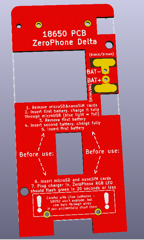
Why I'm currently using 18650 batteries
10/20/2017 at 15:50 • 7 commentsSo, there are a lot of questions about my battery choice. ZeroPhone is known to work with LiIon batteries that have 3V-4.2V voltage range, so both 18650 cells and pouch cells will work (though some chemistries, such as LiFePO4, are not yet supported). So, why not decrease the thickness of the phone by using some kind of pouch cell by default, as opposed to bulky 18650 cells?
![]()
The main problem is - I don't actually have control over which batteries others will use, I can only suggest. Lately, lithium batteries are really hard to ship, so when I send ZeroPhones, best I can do is include a holder of some sorts. So, the kind of holder that I include (and assembly instructions which I include by default) is going to the way I can make I suggestion. Currently, I include a holder for 18650 batteries, and instructions are also tailored to these. It's done for multiple reasons:
---------- more ----------- 18650 are the easiest to source. Sourcing is an important thing here - even if I send out a fully assembled ZeroPhone, the recipient still has to source batteries (since, again, I can't ship those without getting the shipping cost up). With pouch cells, you'd need to source one that fits into 4x10cm dimension (so that it doesn't stick out the ZeroPhone outline), has enough capacity and the right connector. Do I want to subject somebody to this sourcing process when it's all that stands between a working and a non-working ZeroPhone? No way. 18650 cells are easy to get from vape shops, regular online shops, and even harvest from laptop batteries - the latter is where I got all my 18650 cells from.
- 18650 standard size and resulting capacity average. With 18650 cells, you know you're getting about 2000mAh of capacity in one in the medium-to-worst case, you know the length is 65-67mm, the diameter is 18mm + 1mm for isolation, and these things won't change significantly, so you don't have to mod a ZeroPhone case for your battery before printing it, you don't have to worry about finding the right one among many because even the worst ones will likely still fit the requirements.
- Price. 18650 cells are ubiquitous, and they're cheap. Especially compared to pouch cells - I can get 18650 batteries in my hometown for 3.5EUR/one, and pouch cells start from 10EUR/piece (those are not even quite suitable ones). And then, there's harvesting!
- Safety. It's much harder to pierce a 18650 battery, they have venting mechanisms built-in and they're really unlikely to burst in flames - unlike the pouch cells, which are much easier to pierce inadvertently, and they will react violently, and they don't quite have a venting mechanism - they'll just inflate, until they crack the case they're in, or, worst case, get pierced by something.
Having said that, I know that thickness of ZeroPhone has to be reduced, and there are safety precautions that can be taken. So, I welcome everybody that'd like to mod their ZeroPhone to accept a pouch cell instead of a 18650 bank, and I'll eventually provide both instructions and materials for such a mod (namely, JST pigtails and something that could be inserted between back board and the battery to prevent damage.
[TODO: insert a photo of experimental ZeroPhone with a pouch cell here, just need to take it]
-
Visual materials - leaflets, block diagrams etc.
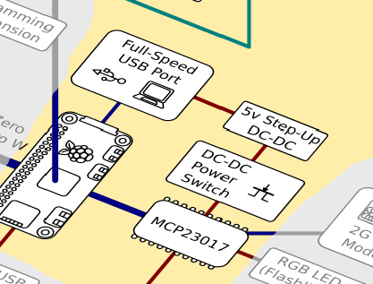
10/16/2017 at 08:29 • 0 commentsThis project log is dedicated to Morning.Star's work on this project. He is, so far, the most active contributor, and he helps with something that I'm absolutely horrible at - art and graphical design. Here's his latest work for our project:
![]()
We're making an easy-to-read block diagram of the phone, so that it's easier to understand what is connected where. This one is still work-in-progress, but this is something that many projects lack - an overview of high-level blocks, that lets you understand how everything is connected without reading a lot of text and going through multiple pages of the wiki. For this project, I believe it's critical to have such diagrams. The more people understand the hardware, the more they can do with it, and that's one of the goals of the project - seeing what others can do with it..
I just sent three phones, and when I was preparing them, I decided that I have to improve their packaging. For example, I'd send links to instructions on starting with the phone by email, and that was kind of cumbersome - you need to get online, read a lot of text, make sense of it and then follow the instructions. There has to be some other way - and inserting a paper leaflet in the box seems like an obvious solution. The boxes I currently use are 194x60x50mm, so I wanted something that'd fit the dimensions and not leave lots of free space. Here's what Morning.Star designed:
---------- more ----------![]()
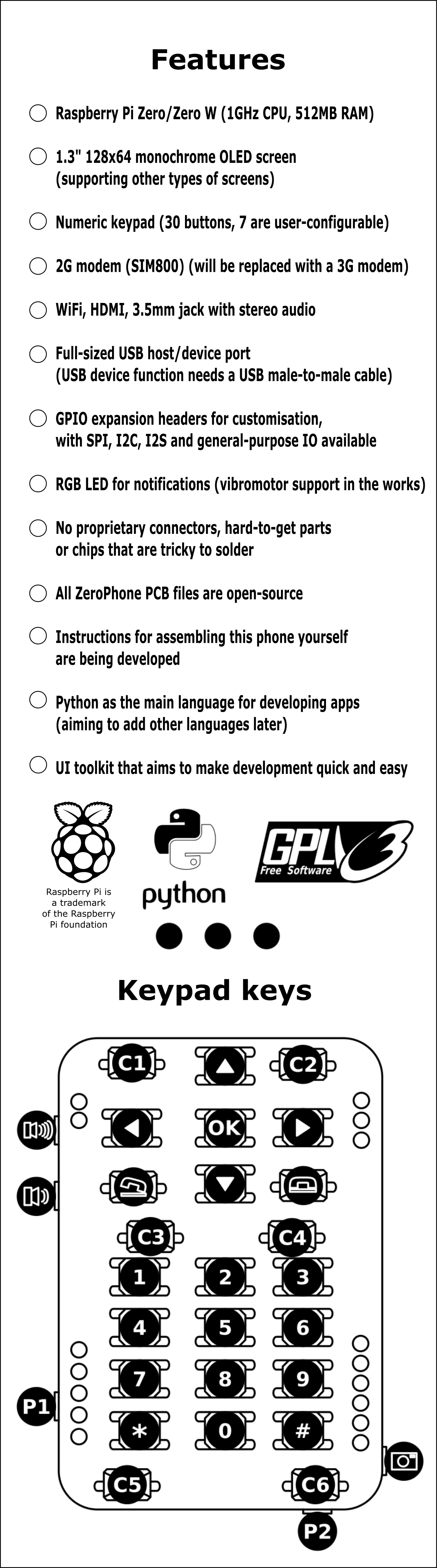
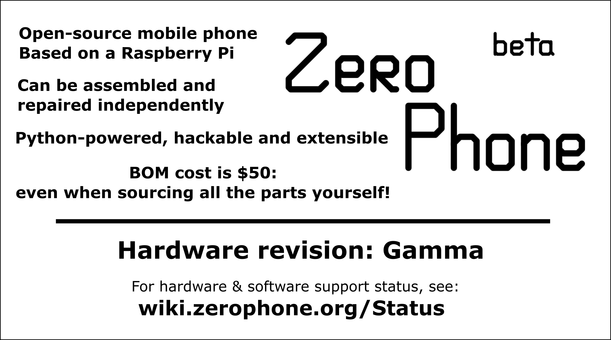
A "list of features, and information on the keypad" sticker, to be glued to the box.
![]()
![]()
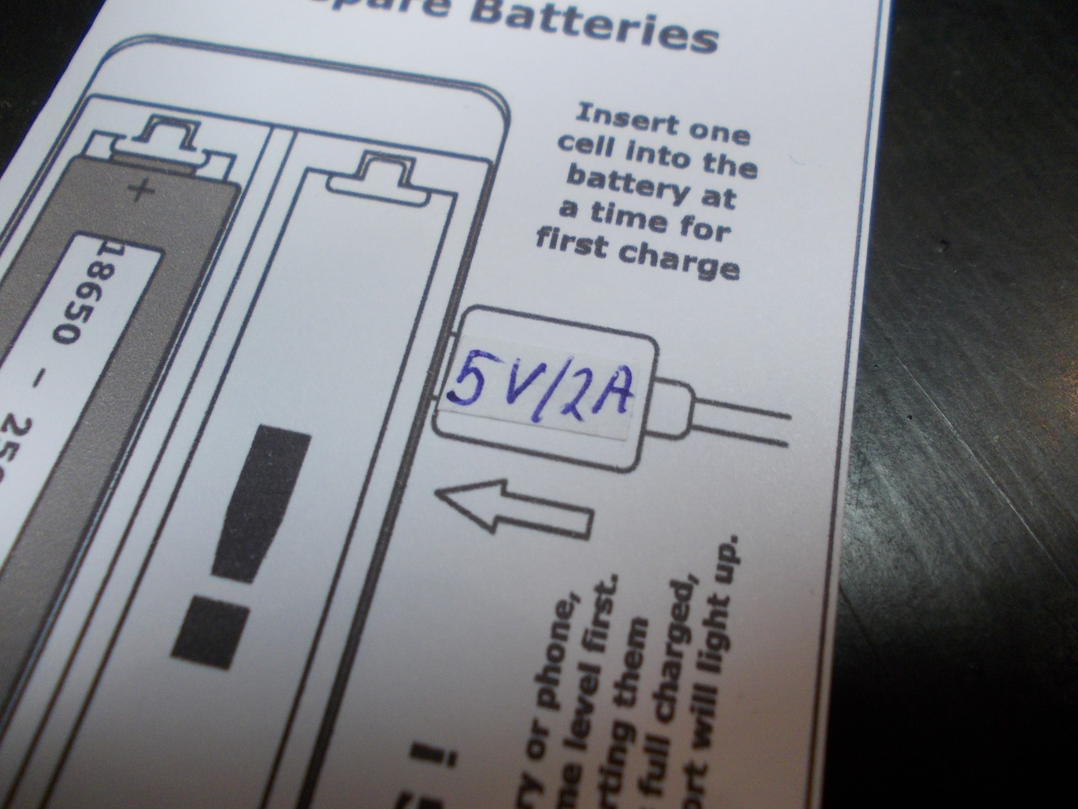
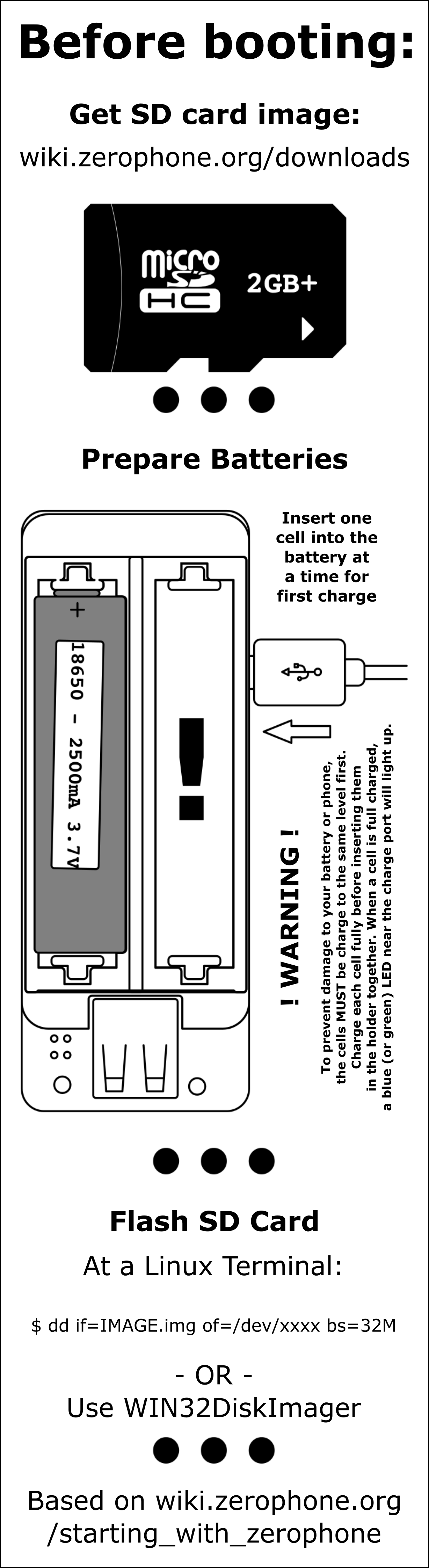
A leaflet to be put into the box along with the phone, with instructions on how to boot it up
![]()
A small 90x50 card, to be glued somewhere on the box/phone - just so that it's clear which revision it is.
If there are some things on the images that are not as pretty as the rest of it, I tweaked them afterwards so this is the likely cause =)
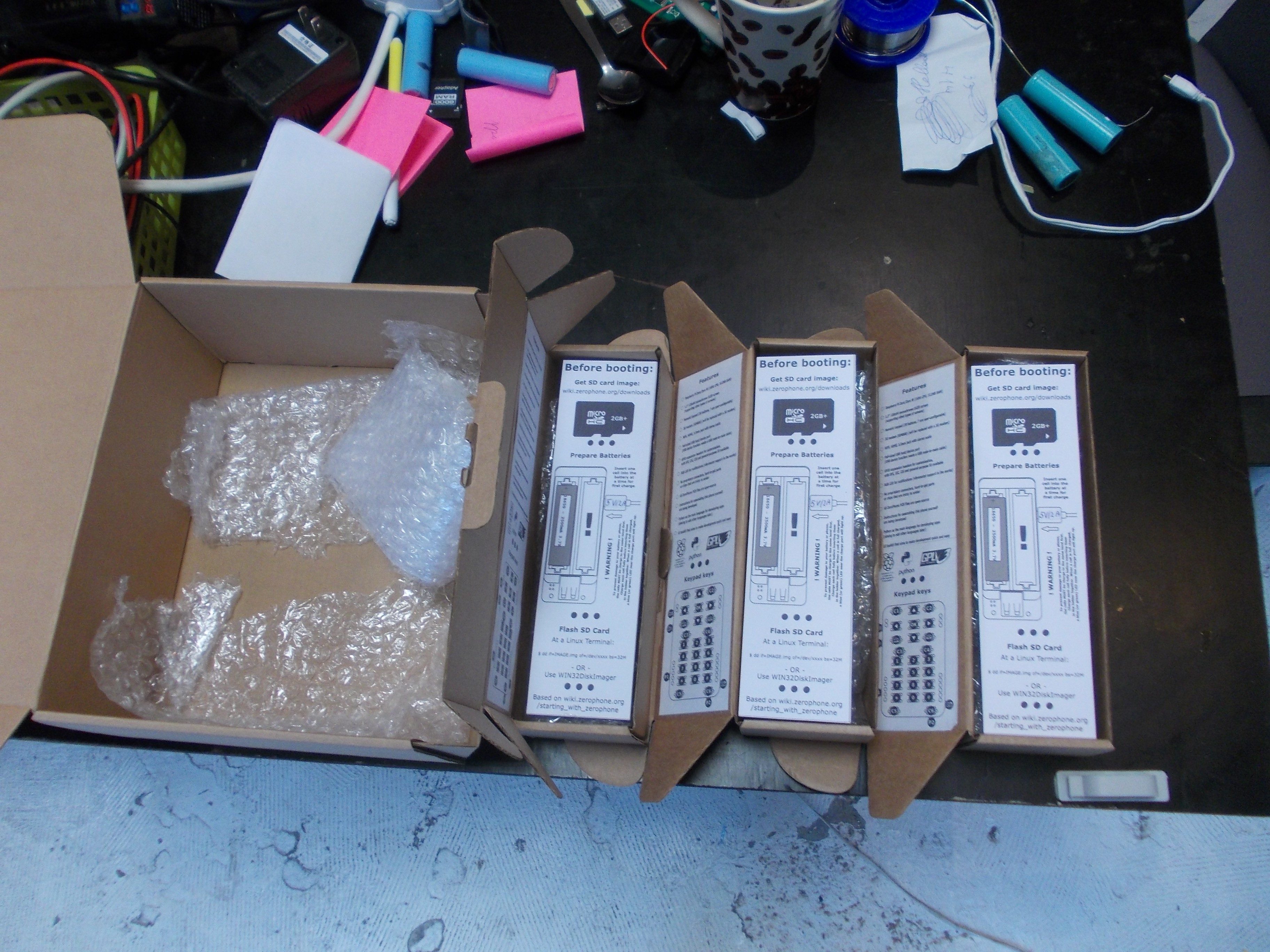
That's how it looks in reality:
![]() Some quick fixes were necessary:
Some quick fixes were necessary:![]()
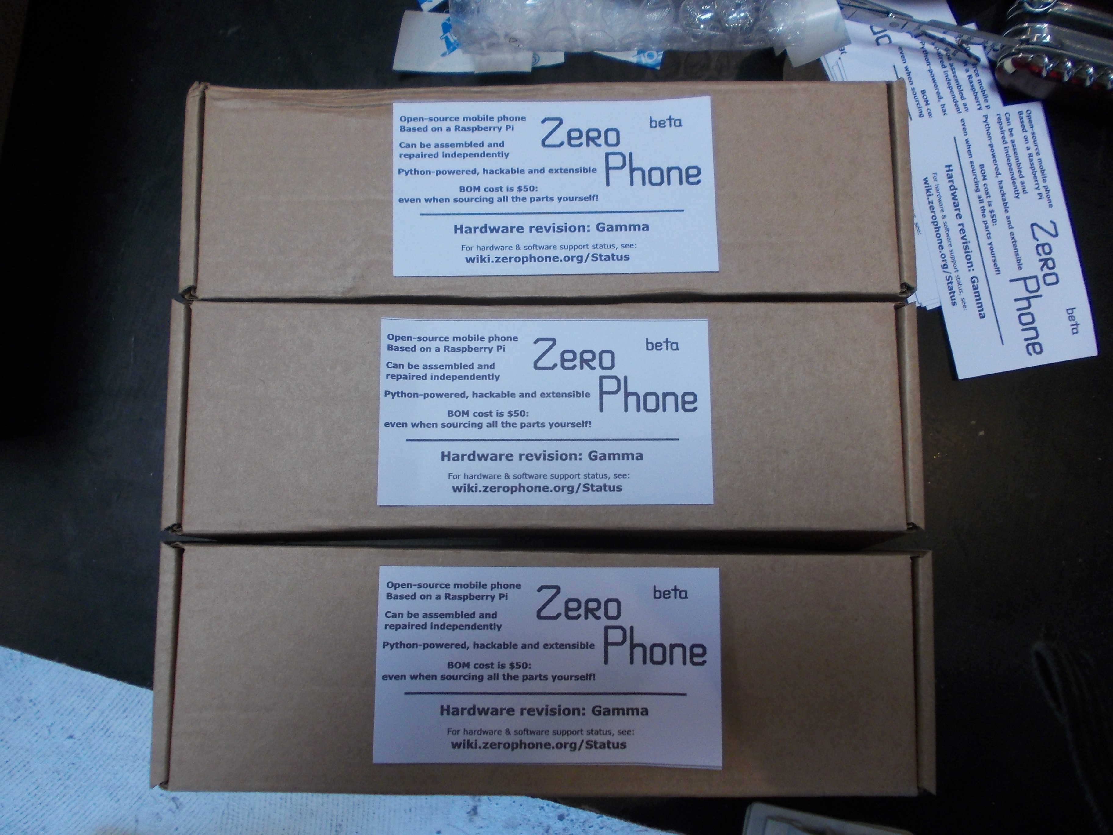
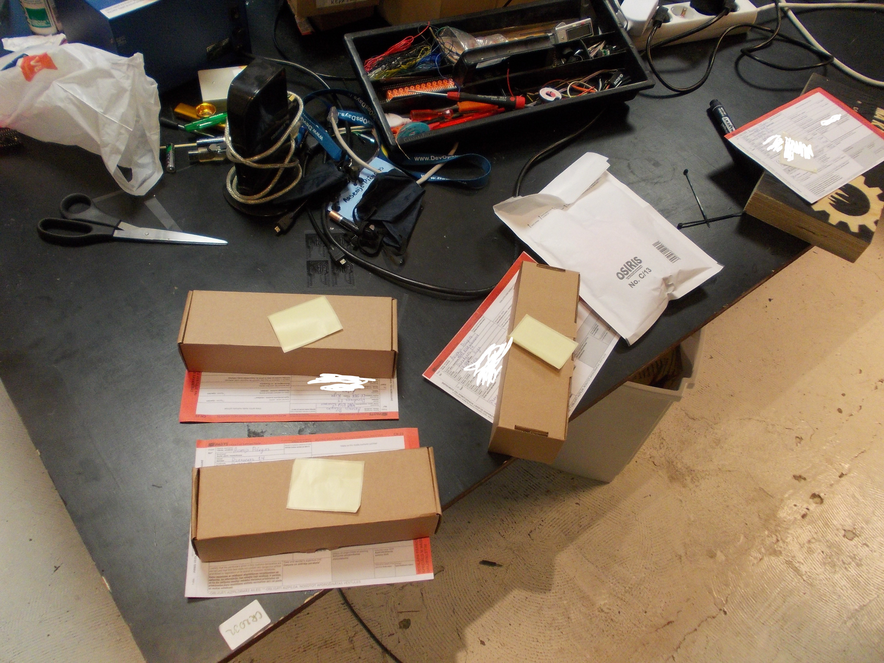
Boxes ready to ship:
![]()
(they were shipped in one big box, otherwise they'd have shipment address stickers on them)
Source files (and .PNGs) are available on GitHub: https://github.com/ZeroPhone/leaflets
Once again, I want to thank Morning.Star for his contributions to the project - he's covering ground I cannot cover, and it makes the project much more complete and useful. Check out his other work, too!
-
How I use my ZeroPhone (part 1)
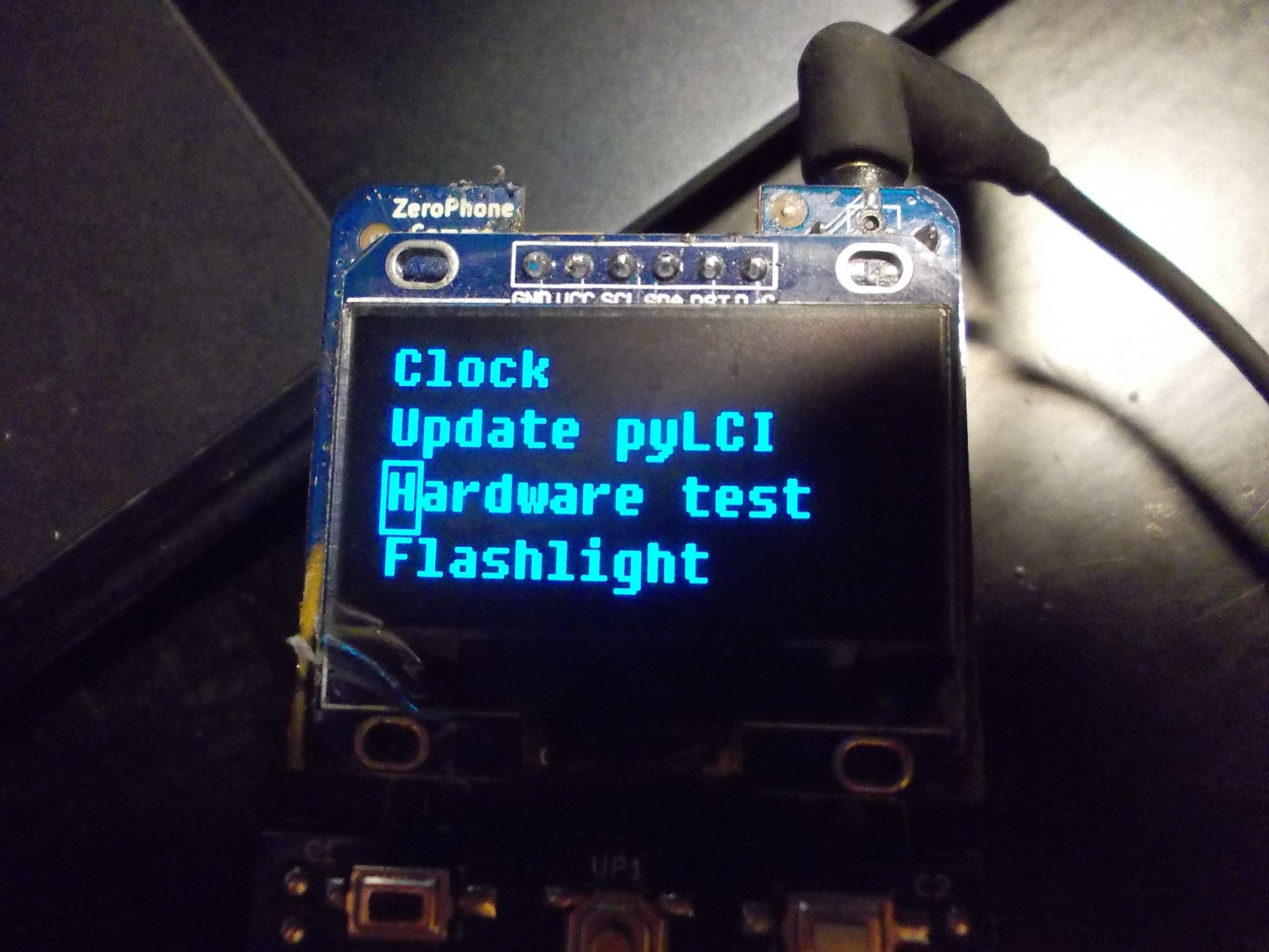
10/16/2017 at 03:19 • 7 commentsI've been using various versions of ZeroPhone for more than half a year now, from just carrying one with me to pretty much depending on having it with me. I've also been thinking about what's necessary to integrate it into my life as much as possible. I'm a hardware hacker that does software, and what I like about ZeroPhone is that I don't have to do a lot of software work to achieve my goals. Still, there are lots of goals and features that I have in mind, and many are not covered by existing software. So, once I write the most important pieces of software that I think ZeroPhone needs, I'll make a followup blog post - right now, I'll show what's possible almost out-of-the-box.
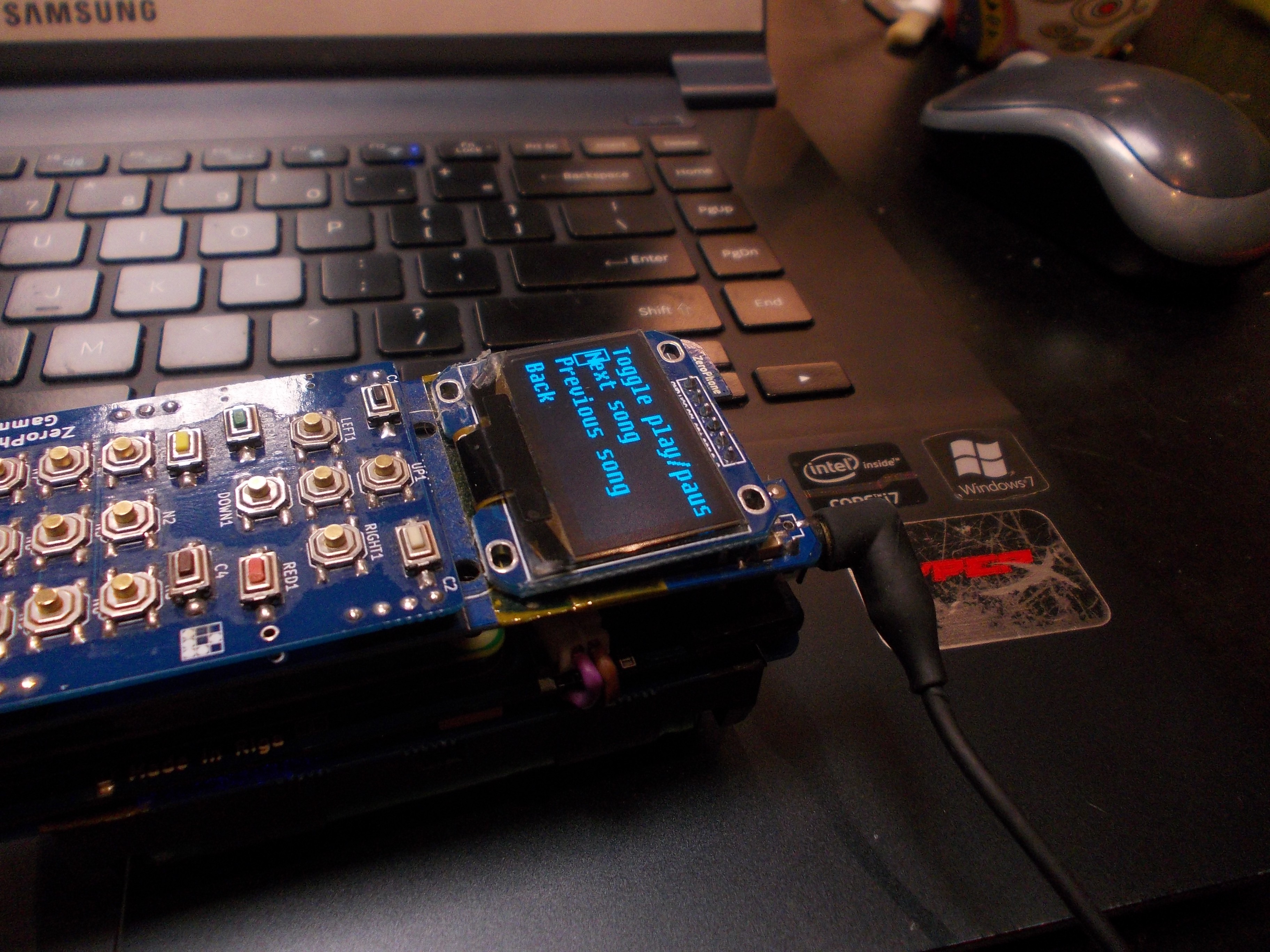
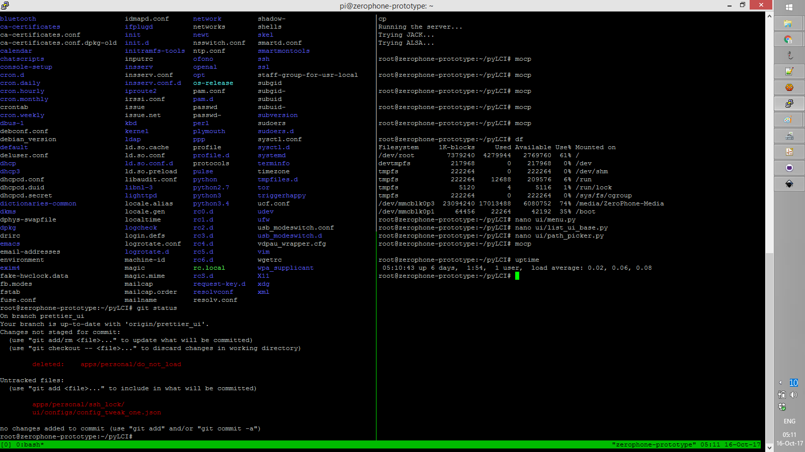
So far, my main usage of ZeroPhone is listening to music, this is the main reason I have my phone 24/7 in my pocket. It drives me, makes me more energetic and gives that boost I sometimes need, turning a boring trip around the town into a quick fun ride and helping me stay in the flow when I'm working. I have a 32GB microSD card, and I've made a 23GB partition on it specifically for music. It seems it's going to be full soon, though - df says that it already has 17GB of MP3s.
![]()
To actually play music, I use mocp from command-line - just point it to a directory, and it plays it (this is the feature that can be really hard to find in smartphone music players, with all their "databases" and "collections"). I have a small pyLCI app to go to next/previous song, and I even have the "next song" available on a hardware key, so whenever a song I don't feel like comes up, I can press a single button to skip it. The only problem with mocp is that I can't actually start it up from the UI after a reboot (you have to use the ncurses UI to make it play the first song). However, it's not a problem - my phone's typical Linux uptime is up to 10 days (assuming I connect the charger each night), it only resets when I forget to charge the battery, or do some hardware hacking that shorts 3.3V to GND =D
To sync music with my collection, I can use whatever tools Linux has for syncing files. In addition to that, I have a Python script that syncs music by reading file paths from a playlist, one more that downloads songs from YouTube if necessary, etc. The point is - I get no artificial limitations in software I use, I can write my own, and if I ever crave better features, like playlist tools or multiple backends, I can switch to something like Mopidy.
Now that I think of it, audio seems to be a promising medium for notifications, enabling certain workflows and improving the UI. Not only it's going to be necessary for accessibility functions (which have been mentioned as a priority in ZeroPhone survey responses multiple times), it can augment the visual UI even for those people that don't actually require accessibility features to use it - if done right.
ZeroPhone has a full-sized USB port, and can run Linux command-line software - so, it's not uncommon for me to use a ZeroPhone and esptool to flash a MicroPython firmware into a ESP8266, develop Python scripts for it in a cozy environment I get through SSH, and then upload the scripts to the ESP using something like ampy. The toolchain I get as a result is something I could never really get in Windows - it's stable, works quickly and is even automatable if necessary. I used to use a separate, Linux-powered, laptop just to do hardware work like this - now it's doable with the phone I always have in my pocket.
![]() ---------- more ----------
---------- more ----------Incidentally, I can also charge a smartphone through this port - even though my tests have shown the current is limited to about 0.5A, then the voltage drops too low to be of use (the DC-DC is not that good). Nevertheless, it works as an emergency powerbank, for when my smartphone is at 2% but I really want to continue reading something interesting, or for when my portable hotspot is low on battery. My further plans with the USB port are to develop a backup app - it'd wait for a specific flashdrive in the USB port, then copy all the personal data from the ZeroPhone (or, alternatively, upload it to a home server once you're home), and could easily encrypt the backup.
I use the USB port more than I expected I would. It's great for general-purpose hardware hacker needs, such as formatting and partitioning flash drives (using the superior Linux tools available for that), reprogramming microcontrollers of all kinds, doing simple RTL-SDR stuff or maybe using a WiFi dongle in monitor mode, to analyze the spectrum, see how many clients are connected.
Last but not least, having a full-sized USB port is great when I have a USB device but I have no idea what it does - I've had that need quite a lot of times, researching or reverse-engineering things, or just getting familiar with something. I can plug it into the ZeroPhone, read the USB VID/PID right from the interface (there's an app for that) and then know . A good, though unlikely, thing is that if the device is a USB killer, I won't lose my laptop to it =D Not to mention the USB2IP potential, for example, which I plan to explore.
Talking about SSH, I SSH into the phone a lot, generally from my laptop, and do all things Linux.
I could write a lot about this - I do my programming, research and experiments here. Somehow, a VM just doesn't cut it for me (especially given that I do lots of hardware stuff), and even though I don't get a graphical display on this, I don't really need it. For example, one thing I now can easily do is getting access to files on a flash drive/MicroSD card with a ext2/3/4 filesystem. Earlier, I'd need a VM or a dedicated laptop, now I just plug the device into ZeroPhone, mount it and use scp to retrieve files.
Fun fact: 99% of ZeroPhone software work is done on a ZeroPhone! I, as many others, wish I could use it standalone, without SSH - and I think I have just the idea that I might showcase when the crowdfunding will be active. Nevertheless, it's fun to realise that I'm actually doing work by using a device which is, at that very moment, located in my pocket =D
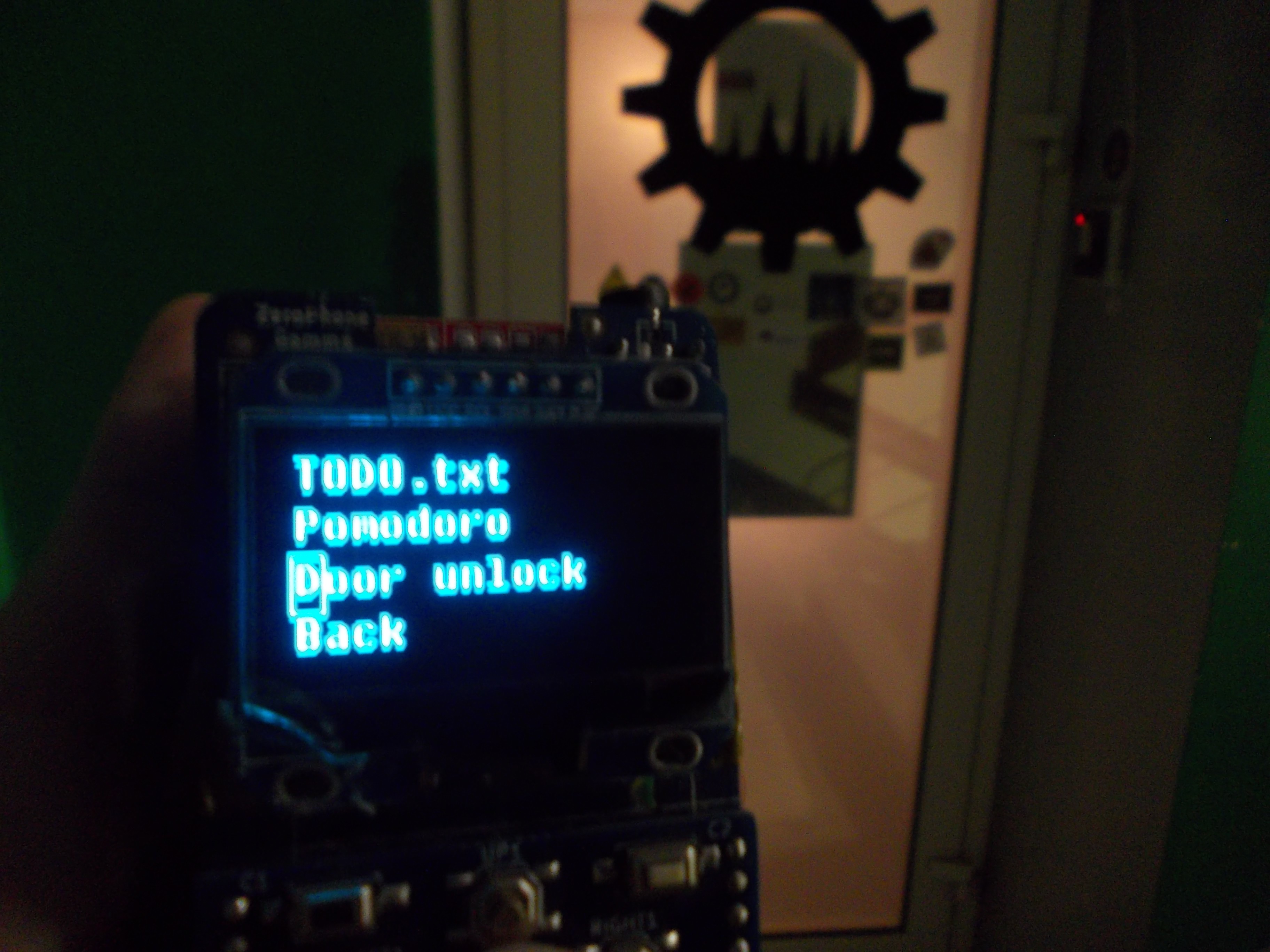
Our hackerspace has a digital door access system. I recently added a SSH server (written in Python) to it, so that members wouldn't have to use RFID cards and could use SSH authentification to open the doors. I created SSH credentials for myself, too, and then I thought - why not create a small ZeroPhone app that'd let me in with one keypress? So I made it in half an hour's time. Here's how the app looks in the "Personal" menu, among other personal apps - press the button, it automatically creates an SSH session (using paramiko), enters my credentials, and the door unlocks.
![]()
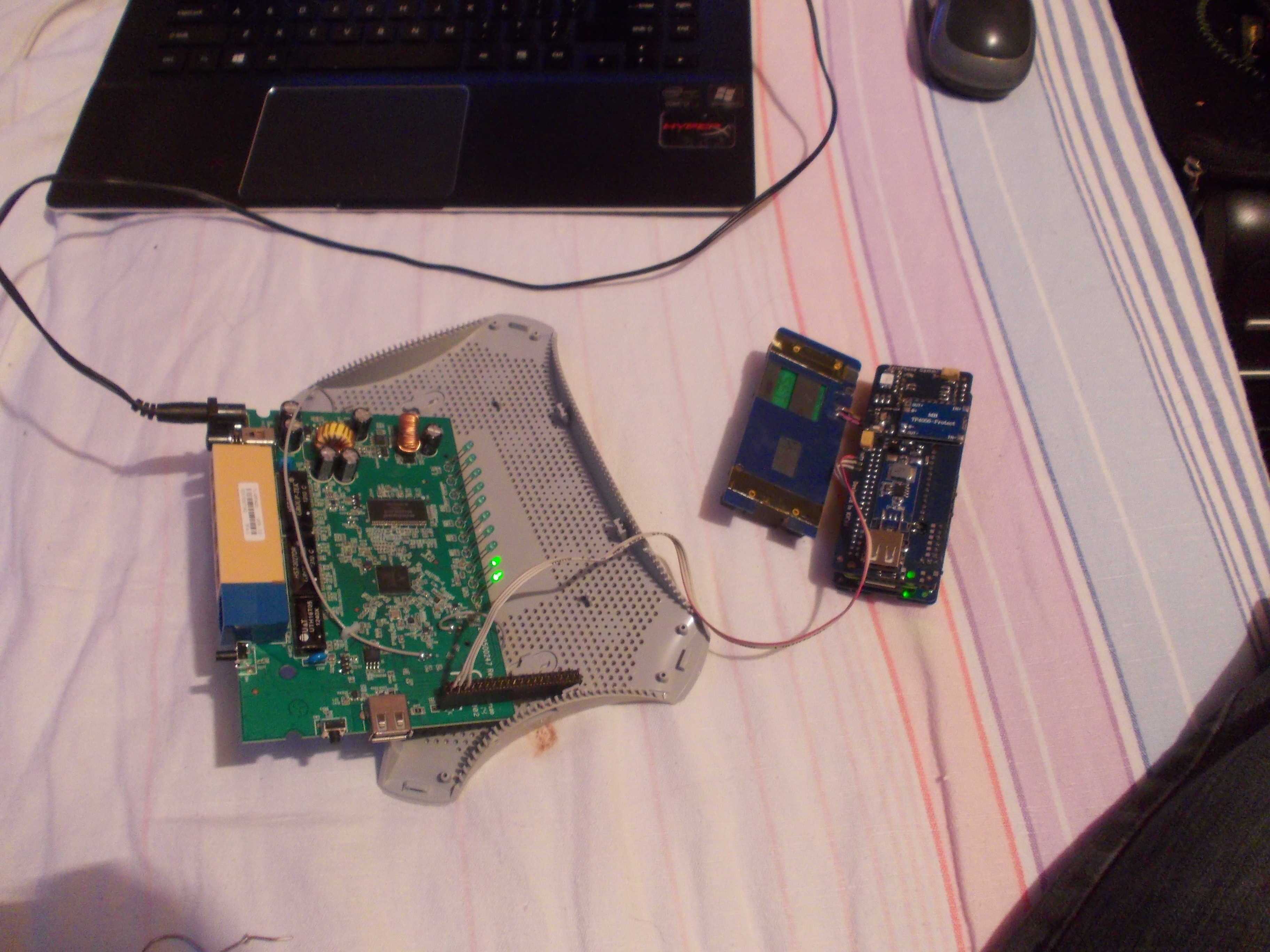
Recently, I got stuck at home when our wireless router broke. I had an old router, flashed with some kind of OpenWRT fork, and I plugged it in - then I realised it was still configured to work with a USB-3G modem. I went to the admin panel, only to realise that I no longer remembered the admin password. Found recovery mode instructions, but it wouldn't go into recovery mode for some reason, so I had to connect through UART and reset the password - or leave myself and my family without Internet access, which'd make for a bunch of unhappy people in one room. I had a soldering iron, found some IDE cable wires, and the only female connector I could find was a 2x20 one. The result:
![]()
...And I got it to work! The wires are soldered to the UART pads of ZeroPhone, and UART is typically connected to the GSM modem on ZP, so I had to put the modem into RESET state (basically, flip one GPIO).
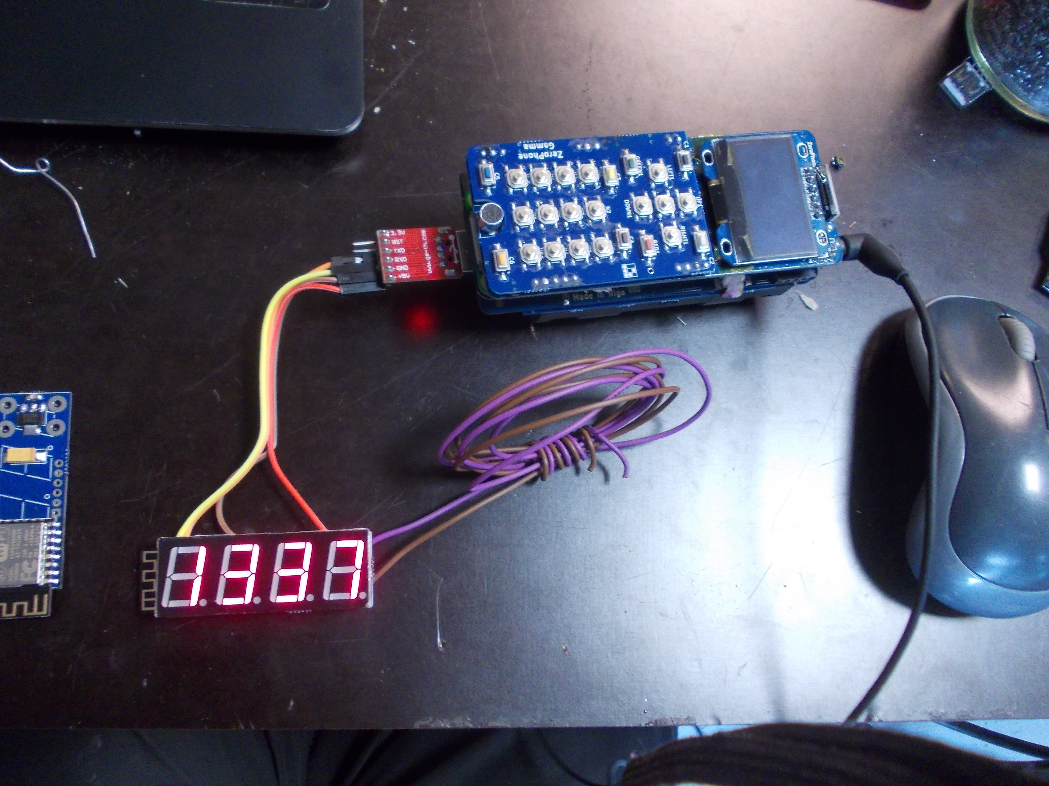
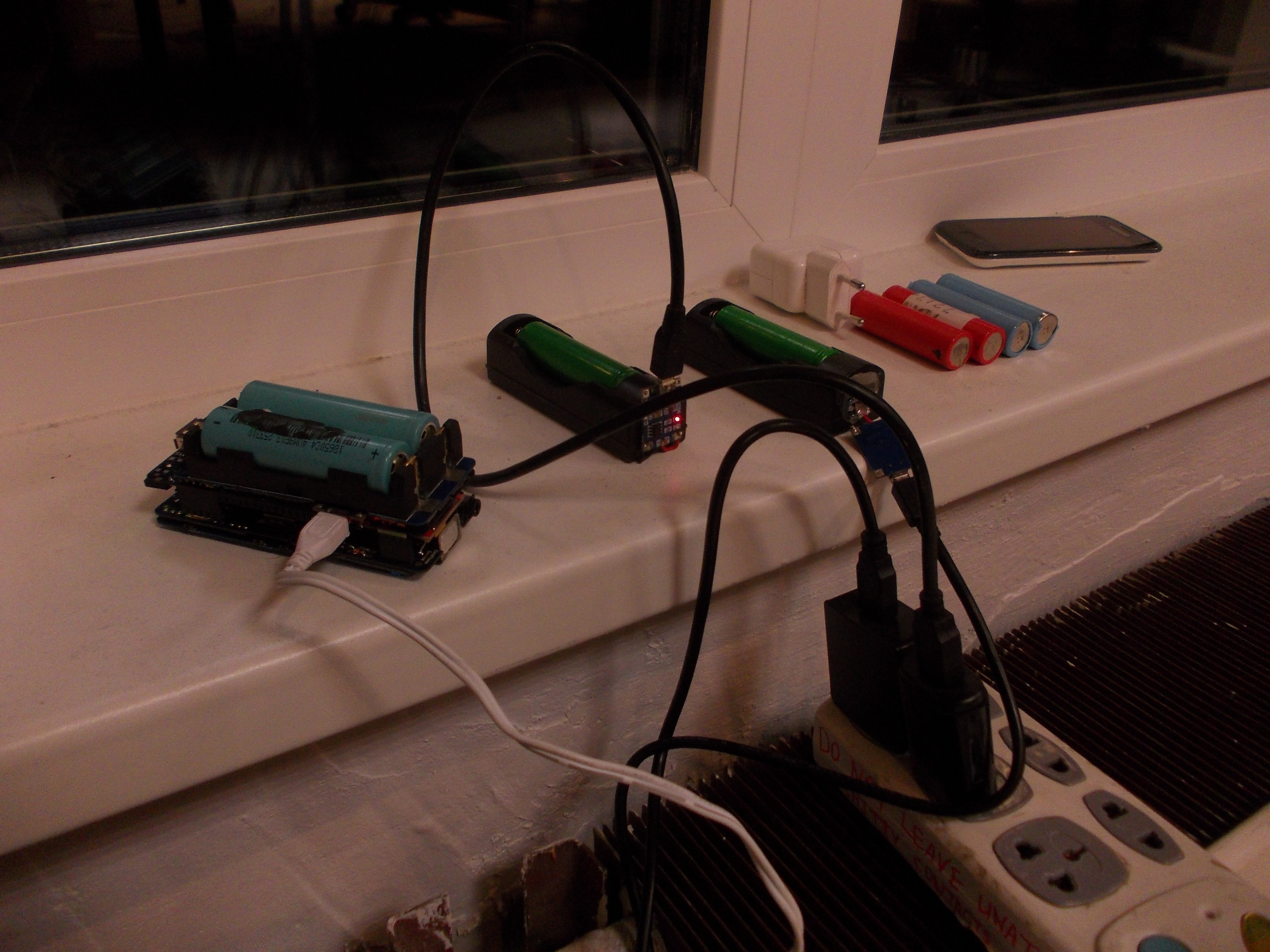
In a pinch, ZeroPhone works as a LiIon battery charger:
![]()
Talking about batteries - while 18650 are bulky, they're easy to source, are very safe and easily replaceable. You can even remove the batteries while ZeroPhone is connected to the charger, and plug fully charged ones, so that you don't have to wait for the phone to charge. What that means is - ZeroPhone replacement batteries are easily available, and they can even be hotswapped! No more "planned obsolescence" because of batteries just not holding a decent charge anymore, 18650 batteries have been with us for tens of years, and are only getting better (and more popular among general populace, because e-cigarettes).
That's it for now. I didn't even talk about expansion ports, and there are much more things that I do with my ZeroPhone, but I don't want to make this worklog too long, and I still need to spend time on making assembly instructions. After that, I'm going to go and see prices for 64GB cards - I want to carry more music with me, just found some albums I'd like to check out, and I don't want to constrain myself. I'm sure about one thing - the upgrade is going to be straightforward, and I might even be able to do it without turning my phone off for longer than a minute - because Linux!
-
Project state: Gamma batch assembly and UI rework
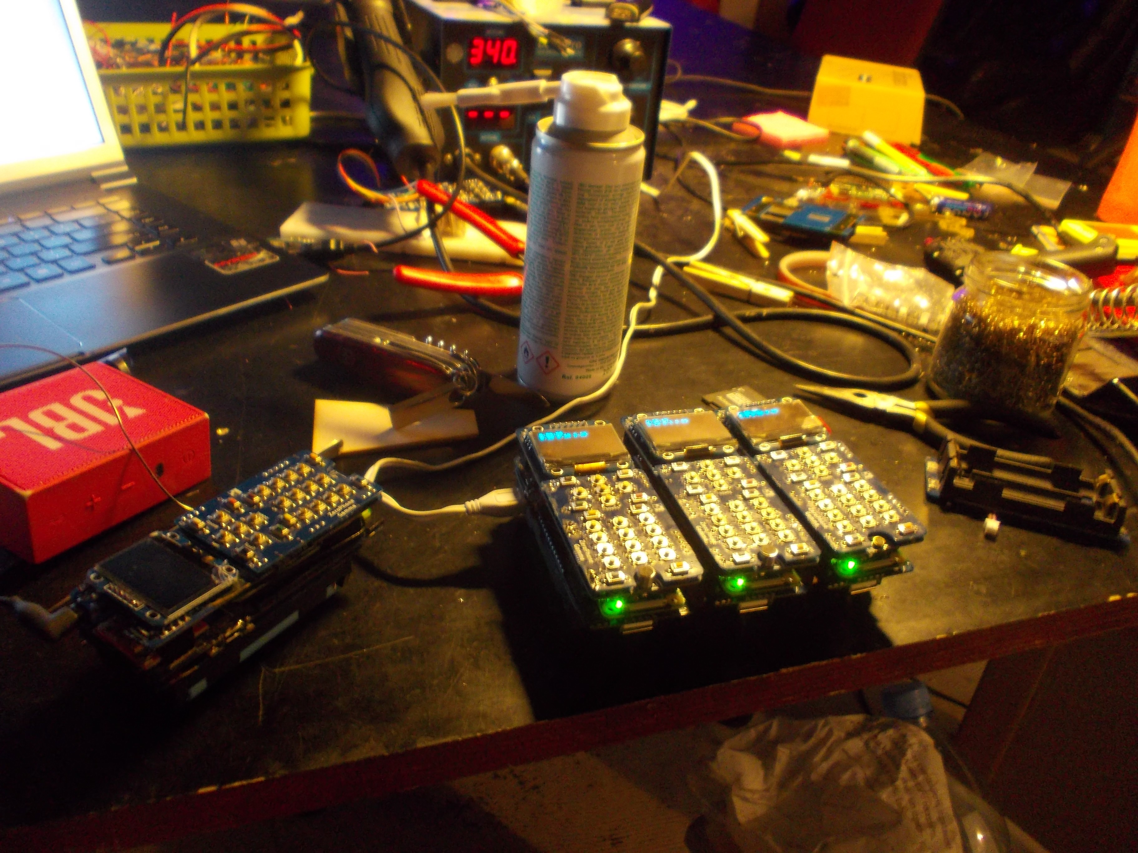
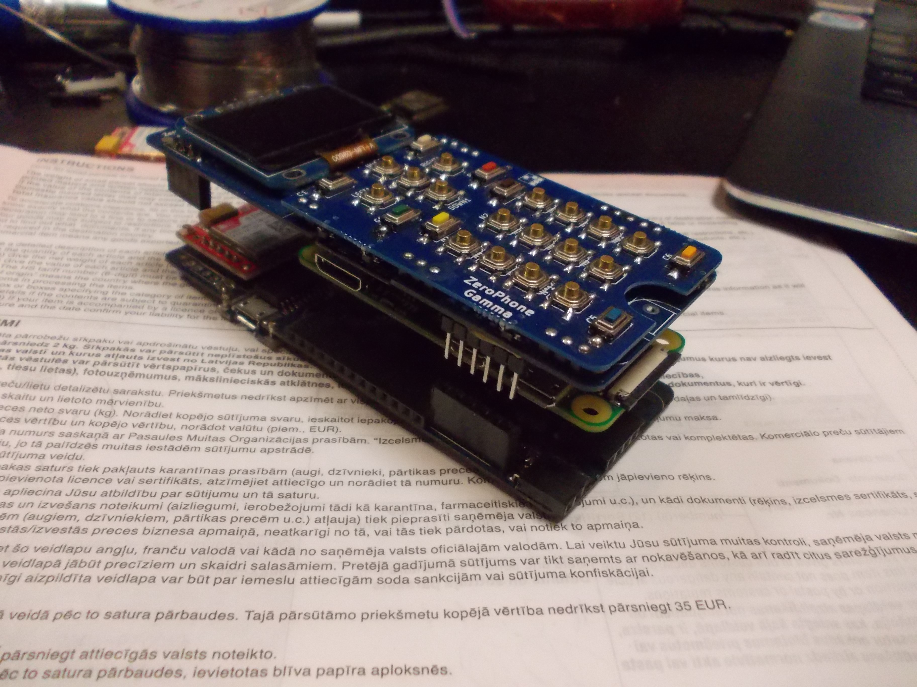
10/15/2017 at 00:49 • 0 commentsAfter the last newsletter, I was on a small 10-day event, which is kind of a vacation for me, since I didn't have access to my tools and everything, and couldn't send out ZeroPhones. Right after that, I went on a hackathon, and from 2nd of October I'm back on track. It's time to send out 3 more ZeroPhones - to Hackaday, for Hackaday Prize Best Product round.
![]()
Here are the 3 phones that I just assembled, in about 7 hours' time - not from zero, of course, all SMD components and some THT components were already soldered on, I had to solder on the USB ports, the Pi Zero, the displays and then make some finishing touches. However, in the following days, I had to do testing and a lot of debugging - so I just wrote down my thoughts on testing ZeroPhones =)
![]() ---------- more ----------
---------- more ----------While assembling all this, I got even more fixes/additions/ideas for the next revision (ZeroPhone Delta), hoping to make it as complete as possible - and I'm going to build at least 10-15 of those, too!
![]()
New 18650 holder board, fixes most of the bugs and problems I had with the current board. Just hoping it doesn't introduce new ones.
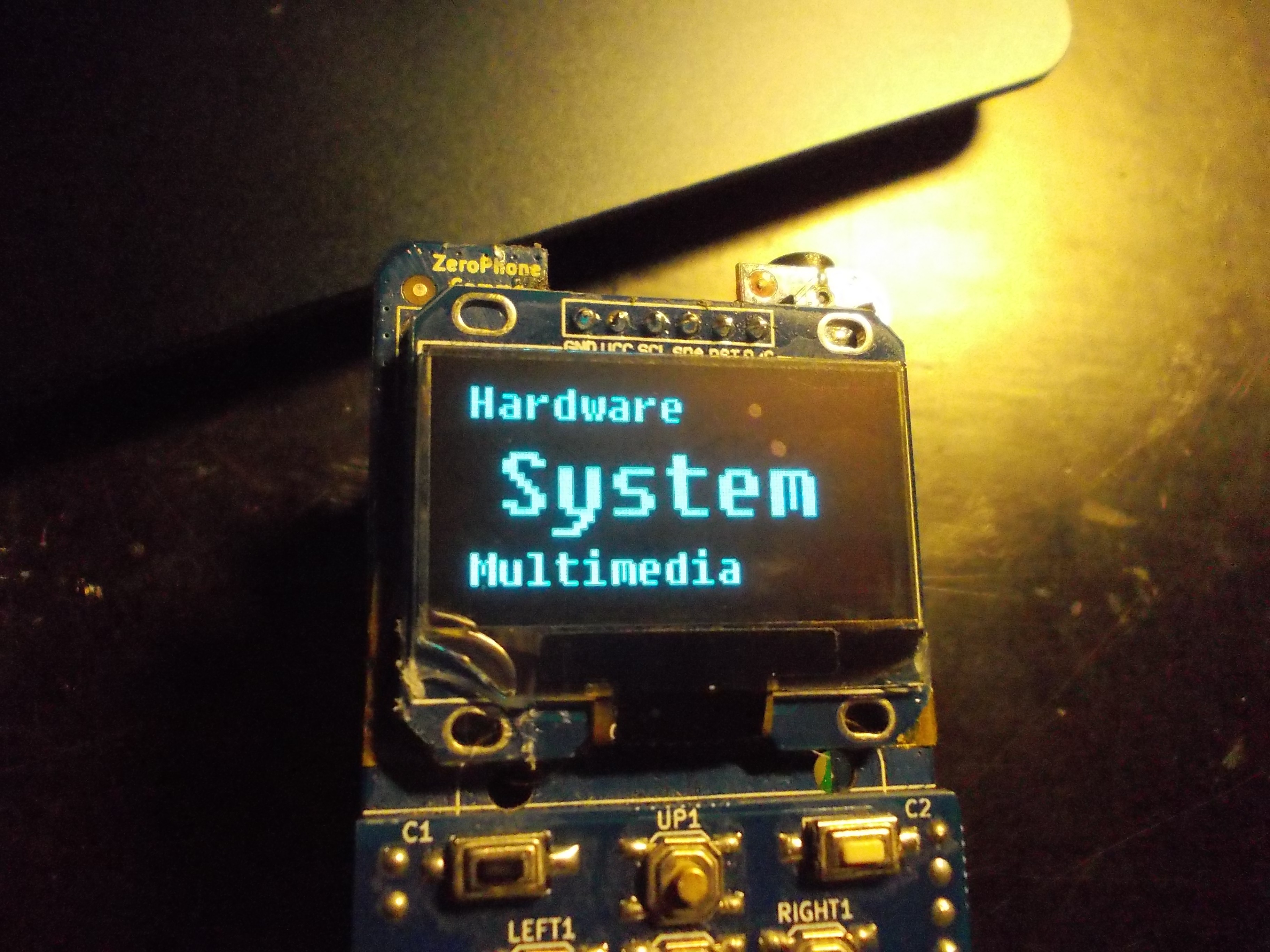
On the event, I still could code, so I fixed a couple of bugs - and worked on finishing the "prettier UI" feature branch. ZeroPhone UI looks pretty basic as it is now, since UI elements used to have text-only representation - so I'm refactoring it, and now UI elements are in control of how they look like. What does it allow to do?
![]()
Custom fonts and bigger letters
![]()
Bringing back menus we've had on older phones
For example, this is something you could meet on a Sony-Ericsson dumbphone (not sure I could call those dumb, though), current menu entry is in the center of the screen and previous&next menu entries on top&bottom. It has no animation so far, so the transition doesn't yet remind of Sony-Ericsson, but it's a great example of what can be done with UI view abstractions I'm putting in place. At some point in the future, I'll make a Nokia 3310 menu, just for fun - you know, the one where each menu entry takes the full screen, but has an animated icon. It's likely going to be highly experimental and won't be mainlined, but it's going to be worth a try for the nostalgy points =)
Furthermore, you can change which views are attached to which UI elements. I've made a simple JSON-based configuration way, so that it's easy to to define, which view is used for this specific UI element or just UI element type, as well as which view is the default. It allows adding new JSON files instead of modifying existing ones, which makes the whole thing a little bit more git-friendly (allowing to update through git using the "Update pyLCI" button in the main menu, without stumbling upon possible merge conflicts). For examples and a better explanation, see a new Wiki page about UI configuration
The new UI is not yet included by default, it's in a separate branch, which will be merge as soon as it's "good enough" - which'll require also adapting the emulator, testing the UI extensively (at the very least, manually) and making sure that the new UI is comfortable to use.
Now, priorities are: accessible BoM (in the form of sourcing guidelines) and assembly instructions. Instructions are already under construction, will be working on those tomorrow =)
-
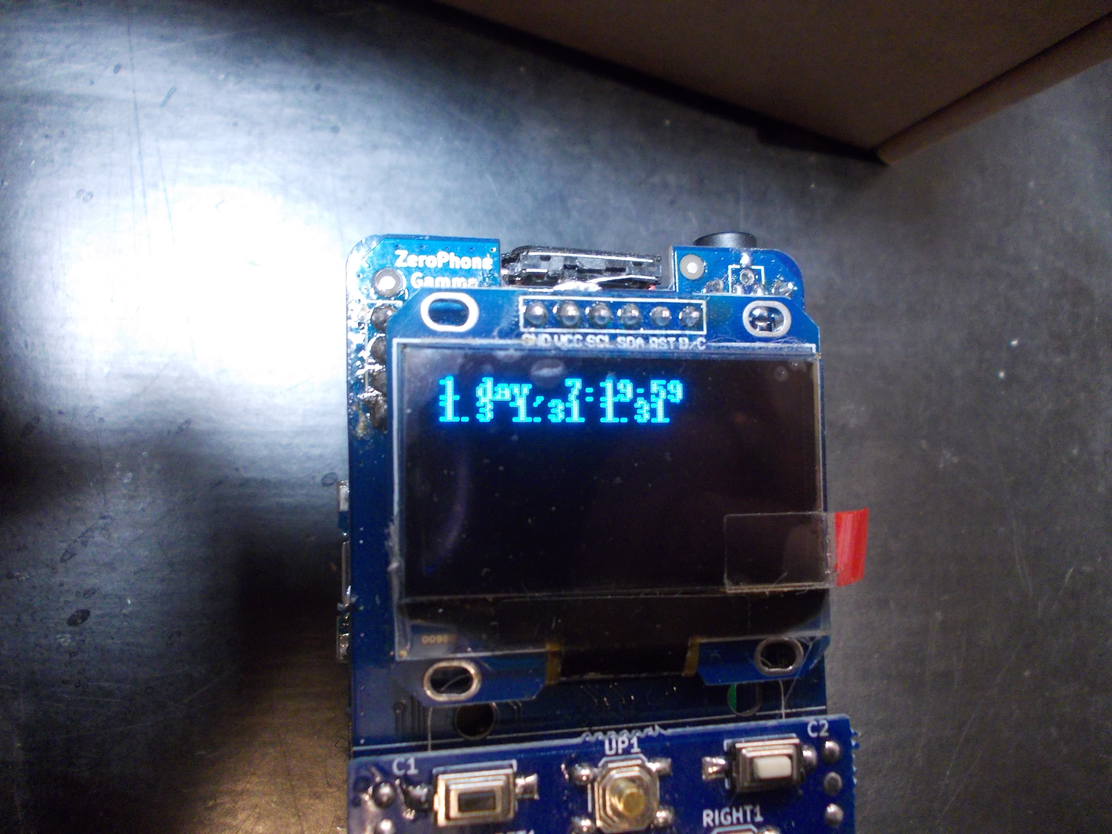
On testing of ZeroPhones
10/15/2017 at 00:33 • 0 commentsI don't yet have a testing stand for testing components that might give trouble. So, when I assemble a ZeroPhone to be sent out, I just put it in my pocket for a day, doing whatever I usually do - going to places with a bicycle, sitting at the desk writing something, doing things at the hackerspace etc - the batteries are good for at least 20h of testing or so. If the phone reboots even once, shuts down, has some kind of other glitch, I know it's faulty, so I know it should be debugged.
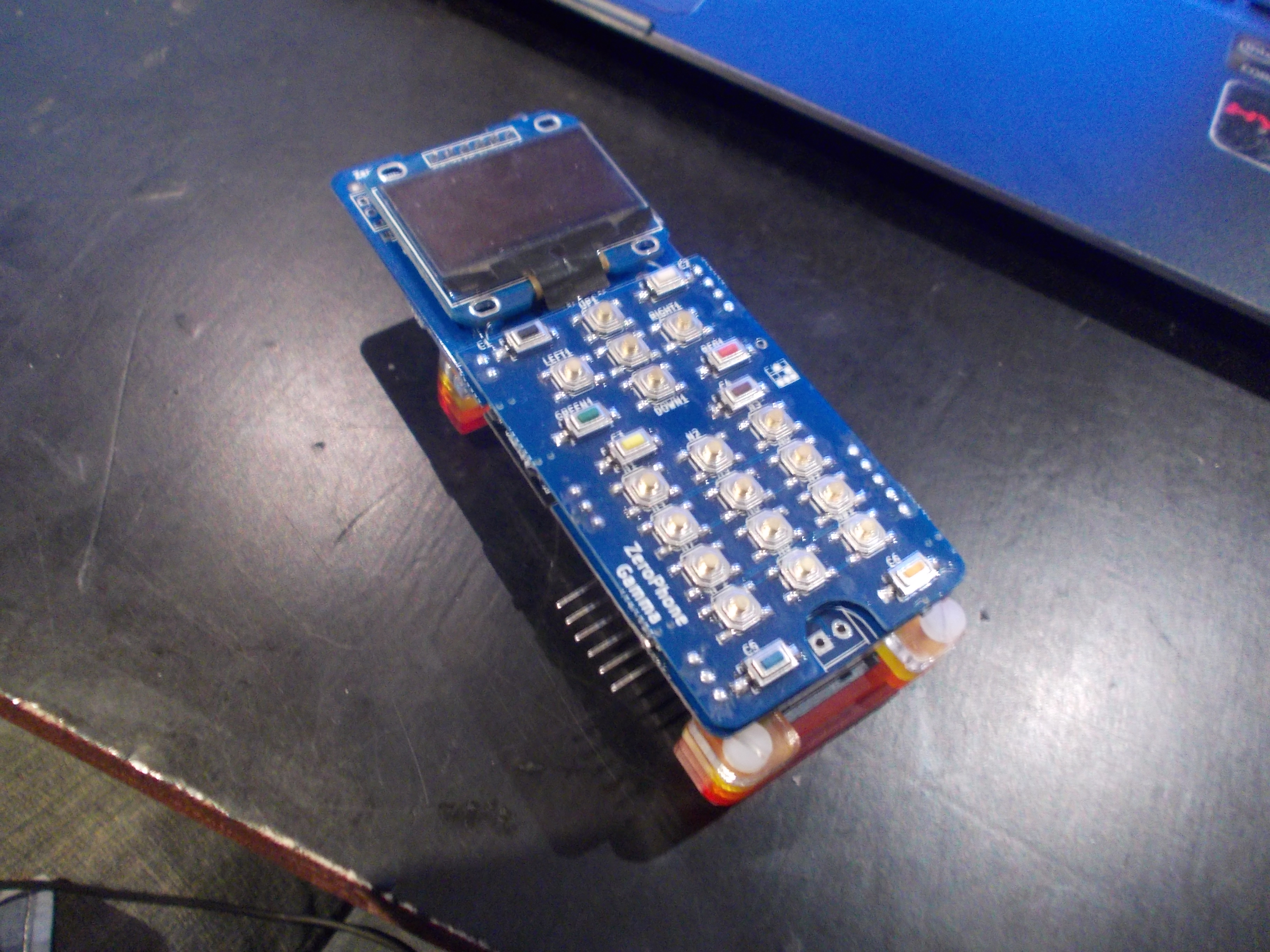
![]()
Uptime of a phone that passed testing
![]()
Two of these phones are going to pass testing - one is going to suffer the "reboot when disconnecting charger" problem
So, with this small batch of 3 phones, I actually assembled two back boards that'd show the same problem - phone rebooting when the charger would be connected/disconnected. I still haven't understood the problem, and since this has to be done ASAP, I just assembled new back boards. So, now I have three back boards that need to be fixed - on one more, the Pi Zero just doesn't boot for some reason.
Of course, piling up broken boards, leaving them to be debugged later on, is not a viable strategy. So, what is it that I need?
---------- more ----------- A testing stand for displays. Even though the LCD troubles are over - I've found the company that manufactures the right kind of displays and they're willing to supply them - I still would like to make sure that the breakouts work, especially if I'll assemble some modded breakouts (nothing unrealistic, since I've already designed replacement 1.3" OLED breakout boards). There could easily be some computer-vision-assisted testing, too, I think.
- A testing jig for protection circuit boards. I've found at least one that was faulty - it's now waiting for me to do some detective work on it. The problem with it is that it'd just shut out randomly, as if an overcurrent condition occured. So, the idea is: test the board with a varying voltage on the battery input and see if it shuts out under fault conditions and doesn't when everything's alright - then probably slap a small "QC" sticker on it or something =)
- A testing jig for 5V DC-DCs. I've had only one fail on me so far out of ~25 I worked with, but that's still a chance I wouldn't like to take.
- A testing jig for Pi Zeros. While it's even more unlikely for those to fail, since they're simple in assembly and are very unlikely to use low-quality parts, it's good to be able to rule out that possibility when something doesn't work, since it's really hard to desolder a Pi Zero from the back board when something goes awry. Also, it's likely going to be the simplest to test, since Pi Zeros seem well-designed from that standpoint - I can connect an SD card using pogo-pins, through testpoints at the bottom, and see if there's UART output, and that's pretty much going to do =)
- A testing stand for assembled front boards. Those might have ATMega problems, or front-to-keypad board soldering problems - right now, I think I'm going to remove the source for most of them by changing the way I'm assembling the boards, but it's going to be important to make sure that a front board doesn't need its solder joints re-soldered by the user.
- A testing stand for back boards, without the Pi Zero. It's important to know that the front board is OK before the Pi Zero is soldered to it. For example, there are 3 voltages on the board - LiIon voltage, 5V and 3.3V. Does any of them short into another? If it does, it's potentially destructive, and if a Pi Zero is already soldered to the board when the fault is discovered, it's going to be difficult to recover the board and refurbish it. On a Zero-less back board, I could easily test the power parts, the MCP23017, the RGB LED and, maybe, something else.
Also, one more thing is that all those testing jigs should be repeatable - so that, if somebody wants to assemble ZeroPhones and sell them, they can spend less time on testing. I could even assemble, say, 10pcs of each testing jig and sell them on Tindie - so that people won't have to source all the different pogo-pins I'll likely be using =)
On low-volume assembly, testing all the parts is something that can be easily automated. What about higher volumes? That's where it gets more important, and tricky. My best guess is that improving the supply chain will do the most - for example, it seems to have helped with displays. Other than that, some kind of "flying jig with pogopins" might do the job - but might as well not work with some more complicated boards. I know who I should ask about this, but I'm not sure I'll be getting satisfactory answers.
So, that's on testing. What about optimization for manufacturing? The thing is - during crowdfunding, I plan to provide ZeroPhone kits, with as much as possible pre-assembled, and a small batch of fully-assembled phones, with the latter being, certainly, the most popular items of the campaign. The more I can optimize for manufacturing, though, the more pre-assembled phones I can sell - and that will directly translate into success of the project. So, that's a subject I'm still thinking on, and asking for advice - I'll make a blog post once I know enough about it, too =)
-
Sending out ZeroPhones; assembly experience
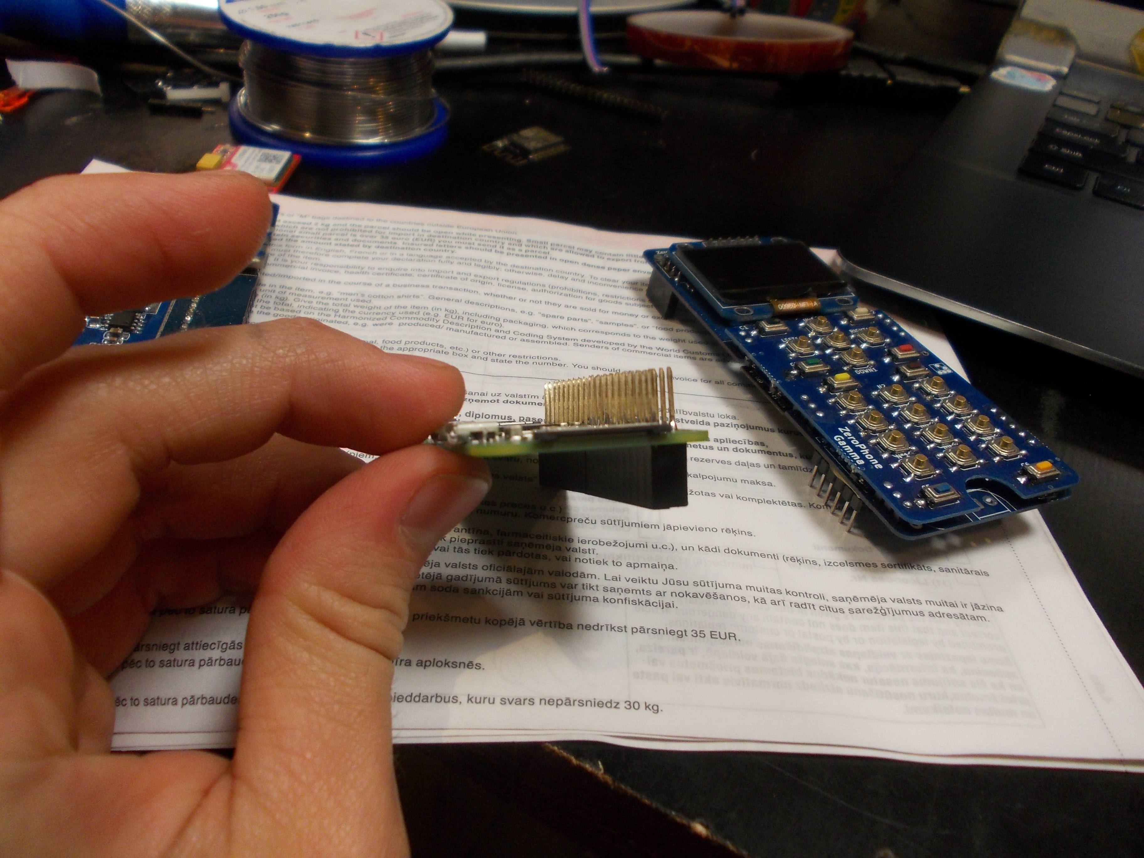
09/18/2017 at 03:03 • 0 comments...I've sent out 3 ZeroPhones before this week, just sent out three more packages and, if I'm lucky, will send out 2 more tomorrow or the day after. These phones are for case designers and other contributors - I'm not yet sending them out to reviewers, simply because it's a tad too early for that. SirCmpwn joined our IRC and expressed interest in working on alternative UI implementations - so I remembered I have just the thing:
![]()
This is pretty much the ZeroPhone front board, without GSM audio parts- it can simply plug on top of a Pi Zero (it's best if Zero is in some kind of case). It's good for developing UI and apps, working on ATMega firmware, as well as just using it as a simple interface for your Pi - with the screen, buttons and audio jack, what's not to love? So, for application development, if I have to send somebody a ZeroPhone and I don't have back board part or a Pi Zero, I can just send this board to allow to start development and then, later, send the rest! I wonder if people will be interested in these during the crowdfunding.
![]()
So, I've been assembling and testing these phones - what I've learned, experienced and started doing differently?
---------- more ----------- Screen breakout problem is solved- I've found the factory that produces 1.3" OLED breakouts that we need, and they seem to be a well-known company. They gave me a quote which is OK, so this part is pretty much set. I still have some breakouts to check - the protection boards, it seems, can be problematic.
- Buying pre-assembled JST pigtails (with wires already crimped) seems to be the way to go. From DangerousPrototypes, they cost $9 per 100pcs (dual-sided cables, making it 200 pigtails), so this-vs-this isn't even a question - it's too time consuming and troublesome to make your own pigtails in this case, whether by soldering or by crimping them with pliers. That is, soldering works pretty good and can be used in case of self-assembly, but I wouldn't rely on it.
- I'll need a testing jig of some sorts, for all three boards. Right now, my way of testing is carrying a freshly assembled phone for a day in my pocket, using it occasionally. It shouldn't reboot (sign of flaky mechanical connections), turn off completely (protection circuit fault) or have other glitches, like keypad keys not working (flaky keypad-to-front-board connections - phone needs to be assembled a little differently than I assembled this batch, which will be reflected in assembly instructions). These three issues only manifest during usage, and, by excluding them in the next revision, I won't need to carry a phone in the pocket for a day anymore. So, only "works or doesn't work" issues will remain - and a testing jig will speed up testing for these significantly.
- Packing ZeroPhones for shipping is actually pretty easy, Take a 194x50x60 cardboard box for 0.50EUR (that's what a "all things dead trees" store nearby sells), separate the battery holder from the phone, wrap them in bubble wrap, put in the box and mail it. There's even some room left - I now fill that with some Latvian chocolate =) Each package turns out to be about 200 grams, max. Of course, I don't ship batteries - but given that 18650 are now easy to get in vape shops, I don't worry about that too much.
- To make the assembly easier, I need to add significantly more silkscreen markings to the boards. Here's a GH issue with all the markings I've planned so far - I might add more if necessary. I guess I'll need to remove some silkscreen art, and I don't know whether I'm within cheap board fab silkscreen tolerances when doing my changes - I'm guessing that $70 spent on new boards will tell =D
- Screens need reverse polarity protection, as does the ATMega header. I'll see if I can think of something for the ATMega header, and screens are not something I can control - but not in the case of breakouts I designed myself, which have a FET for reverse polarity protection! (though, come to think of it, data lines are still unprotected)
- I got some fully-assembled faulty boards that I haven't yet determined fault causes for: one back board and three front boards. As I'm solving problems like these, I know more and more about what can break during assembly, and which components to check before soldering them on =)
- I need to check the buttons. I'm not sure if the current buttons are rated for lots of presses, and I've already had some buttons fail on me. This problem will likely be solved by a case, but I'm probably going to try doing some stress tests, too.
I'm going to add more points to this post in the next couple of days, as I remember more and more things.
A kind-of-a-testing-jig I'm already using:
![]()
![]()
It's good because 1) I can easily test out back boards before I solder the Pi Zero on 2) I can also send boards without Pi Zeros if I'm out of Pi Zeros for some time, like it is now - I'd be happy to send out a couple more ZeroPhones, but I ran out of Pi Zeros and I don't have time to order one (I'm leaving Latvia for 8 days the day after tomorrow), so I'm desoldering Pi Zeros from my previous projects =( Later, I'll also post some more testing jigs that I've made!
Oh, and I'm writing a small Python script to automatically download newsletters I make and upload them to the archive. So, instead of 10-15 minutes, it should then take about 1 minute, so it's not as much of a blocker as now, when I've got two newsletter editions that are still not in the archive.
ZeroPhone - a Raspberry Pi smartphone
Pi Zero-based open-source mobile phone (that you can assemble for 50$ in parts)


 Some quick fixes were necessary: