 Arya
Arya-
Challenge: Zero W Bluetooth problem
09/13/2017 at 23:23 • 0 commentsBCM2835 has two UART interfaces available - one "stable-frequency reliable UART" and one "unstable-frequency not-so-reliable UART". Currently, ZeroPhone re-maps the "stable frequency UART" to the GSM modem, because GSM has a higher priority in the project. Bluetooth, in turn, is re-mapped to the "unstable UART" - and that's where it stops working, I didn't really look further, though here's something that looks like a solution.
Can you help with getting Bluetooth to work in the basic configuration, as it is? Instructions:
- Get a Pi Zero W or a Raspberry Pi 3, upload Raspbian on SD card, boot it and log in
- Add one line in /boot/config.txt: dtoverlay=pi3-miniuart-bt
- Reboot, check that "hcitool dev" doesn't list any Bluetooth adapters anymore
- See how Bluetooth can be brought back to life, and somehow assess how reliable it is.
- Write instructions, which are to be included on ZeroPhone Wiki.
The stakes are, undoubtedly, high, and rewards consist of some Latvian chocolate mailed to people that help the most =) Performance and compatibility tests with various Bluetooth devices (ideally, audio output devices and streaming music to them) and any other insights will be highly appreciated.
UPDATE: "The thread you linked works for a Rpi3, but not the Rpi0w." So, we need to dig deeper - there's some action going on in the linked thread.
-
Mod boards and expansion ports
09/13/2017 at 14:31 • 5 comments![]()
ZeroPhone, apart from being an open hardware&software smartphone, is hackable and, therefore, has a couple of unused hardware interfaces - like SPI, I2C and I2S. They can be used for electronics tinkering, reverse-engineering and adding features - but what better purpose there could be for them, if not having optional hardware additions to ZeroPhone?
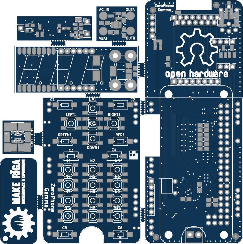
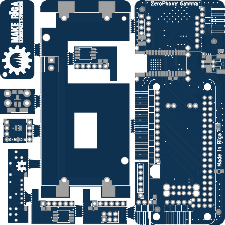
So, first additions have been attempted with ZeroPhone Gamma version - I've designed three boards - one audio filter board (I later found that the power regulator I picked was too noisy), one SPI flash chip board (where I've accidentally miswired the pinout, so it wasn't usable and would burn flash chips inserted into it), and one ATMega programming board (which should work, but didn't have enough silkscreen markings or documentation to actually be useful). For the next version, I'm working on 15 different mod boards, and I'll add some more later- they'll likely be offered as addons during the crowdfunding. Let's see what some of these mods can offer!
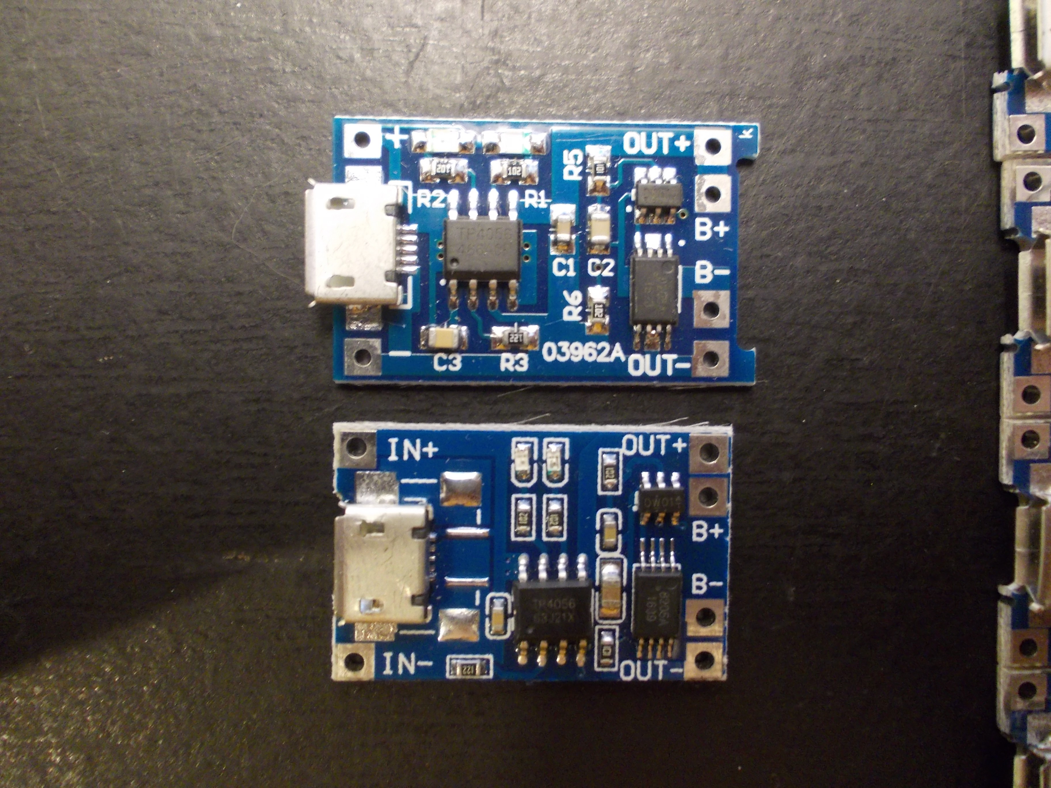
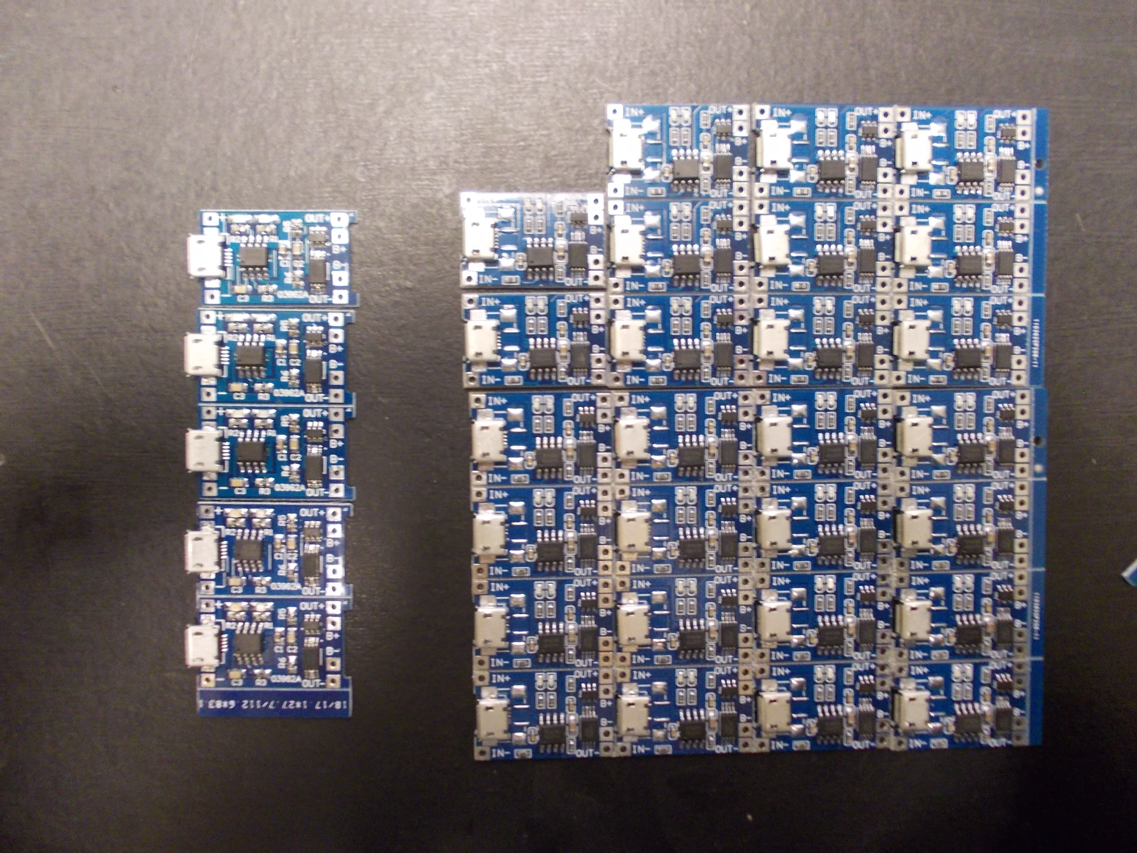
---------- more ----------TP4056 charging+UART board
![]()
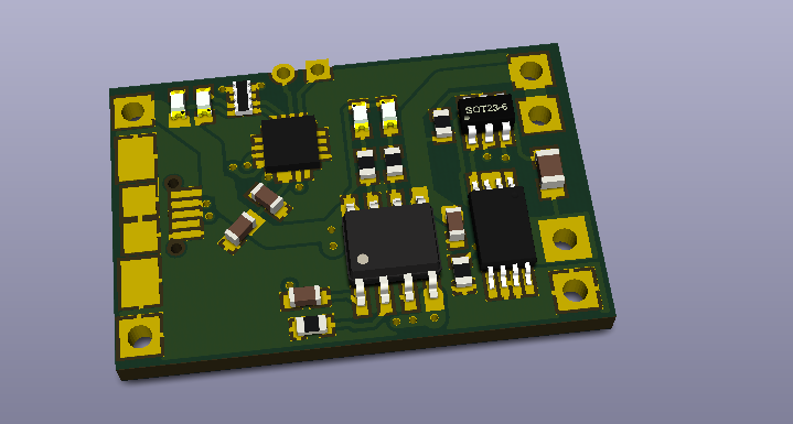
Currently, the MicroUSB socket on the side of ZeroPhone is only used for charging. One person (that received the ZeroPhone from the ZeroPhone Gamma batch) suggested adding a USB-UART on that port for debugging - so here we are! I reverse-engineered the original TP4056 board and designed in a USB-UART chip, CP2012N in QFN-20 - the smallest one I could find. This board also will require modifying the back board a little bit, bringing the UART testpoints to the bottom of the back board, but that doesn't seem like too hard of a task - though I haven't yet done it =) This board is supposed to replace the original TP4056 board, so some soldering will be required in order to swap the original board for this one - but, for the crowdfunding, I'm sure it won't be too much of a problem, especially with kits, where the board will be supplied separately anyway.
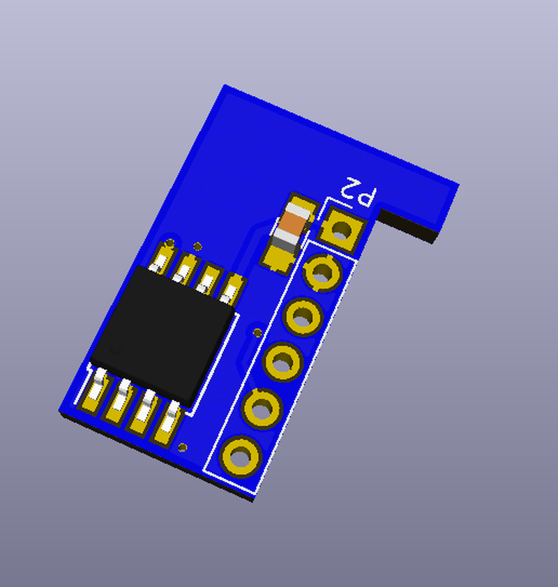
Microphone board
![]() ZeroPhone is lacking in the "audio" part, compared to the smartphones we have: the audio on current smartphones is highly integrated (with lots of audio paths and some specialised ICs for switching them), and ZeroPhones are assembled from widely available parts, those two contradict each other. Currently, there's 1) GSM audio - speaker and microphone connected to the GSM modem, not accessible to the Pi Zero in any way 2) audio output from the Pi Zero on the 3.5mm jack, not accessible to the modem in any way. So, it's kind of limited - especially given that USB sound cards aren't really an option.
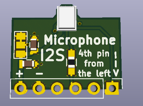
ZeroPhone is lacking in the "audio" part, compared to the smartphones we have: the audio on current smartphones is highly integrated (with lots of audio paths and some specialised ICs for switching them), and ZeroPhones are assembled from widely available parts, those two contradict each other. Currently, there's 1) GSM audio - speaker and microphone connected to the GSM modem, not accessible to the Pi Zero in any way 2) audio output from the Pi Zero on the 3.5mm jack, not accessible to the modem in any way. So, it's kind of limited - especially given that USB sound cards aren't really an option. Thankfully, there's I2S on the expansion header - so we can re-use the Adafruit findings about the SPH0645 and make a really simple board with this small and cute microphone. It's going to stick out of the board edge a little bit, but only because that's the only reasonable way of mounting it that I see so far.
![]()
RFM12/RFM01 board
![]()
GSM and WiFi can't be the only wireless communication standards that ZeroPhone can support. There are widely available RFMxx modules, and, for a start, this is a board that houses such a module, making it easier to add ISM band communications to ZeroPhone. Yeah, there isn't any official software support for Linux, as far as I know, but existing Python libraries will likely work just fine =) Boards for newer&better RFM modules will likely follow.
Infrared receiver/transmitter board
![]()
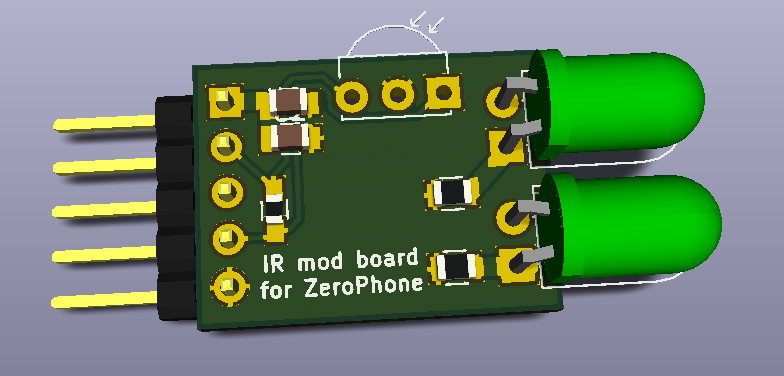
Infrared might be considered dead - but in my opinion, not quite! There are still devices that use infrared, like AC units, those large TVs in cafes, projectors, and I even have an old keyboard that operates on infrared. This board plugs into a 5-pin socket on top of the ZeroPhone and adds some IR LEDs and an IR receiver to the ZeroPhone, and the combo is well-supported by LIRC - in fact, IR signal to key event mapping was my first completed Raspberry Pi project!
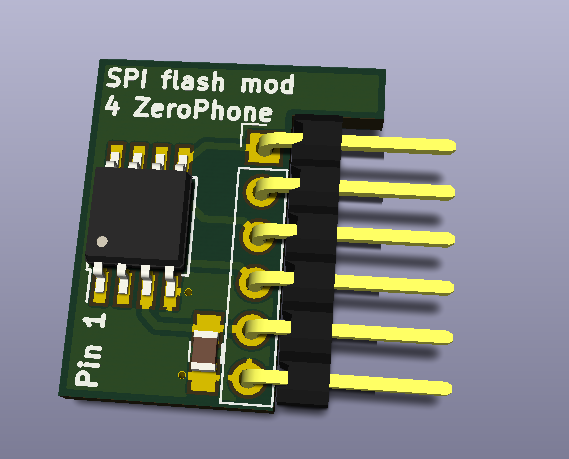
SPI flash chip&I2C EEPROM programming boards
![]()
SPI flash chips are widely used for storing various firmwares - on laptop&PC motherboards (BIOS/UEFI storage), routers and other embedded devices, boards like ESP8266-modules and, undoubtedly, lots of other interesting tech. Those chips can be read using an SPI port - which ZeroPhone, very conveniently, has on the 13-pin expansion header. What does having this board mean?
- Ability to re-flash BIOS on your x86 device - for example, with Libreboot/Coreboot/BIOS with Intel ME neutralized. As of lately, it's harder and harder to flash a custom BIOS through software - that means we have to revert to hardware flashing methods, and this board takes a lot of pain out of hardware flashing.
- Ability to fix a router with broken firmware, or revert to a known working one. Sometimes, flashing OpenWRT/Lede/new stock firmware on a router just goes wrong, and router is bricked, sometimes needing something like TFTP over an Ethernet cable and USB-UART to revive it, and sometimes being completely unresponsive to even methods that are claimed to be working. Or, say, you want to play with new firmwares for your router, without having to rely on software failsafes for re-flashing - then flashing firmware into the chip itself is the most reliable way. Also, it makes you able to easily do a safe backup of crucial areas, like RF calibration partitions.
- Doing reverse-engineering of new gadgets that use this kind of flash chip - which can be encountered occasionally.
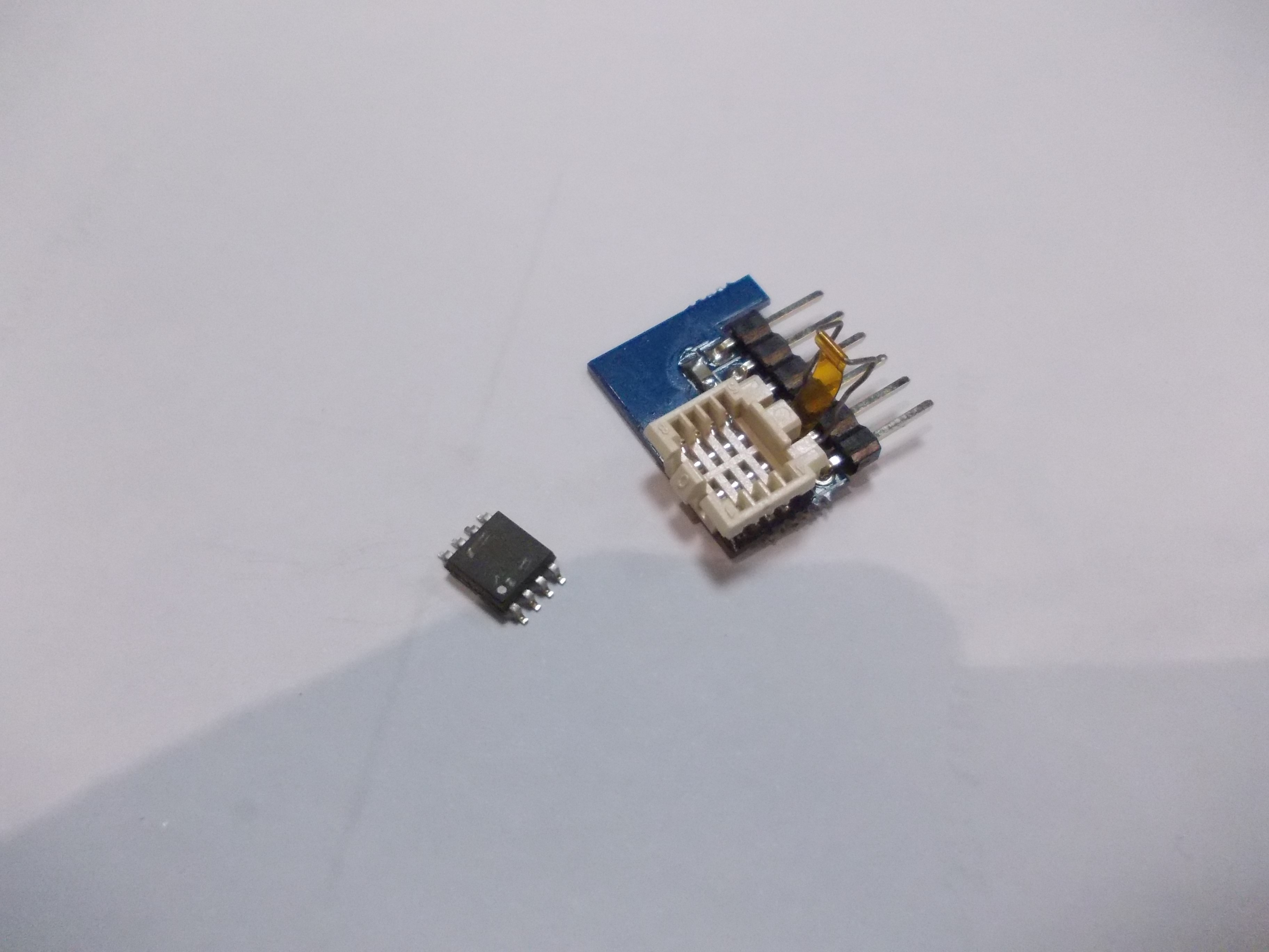
So, ZeroPhone with this board essentially works as an SPI flash chip programmer. The killer feature of this board is these zero-insertion-force sockets I've found on TaoBao:
![]()
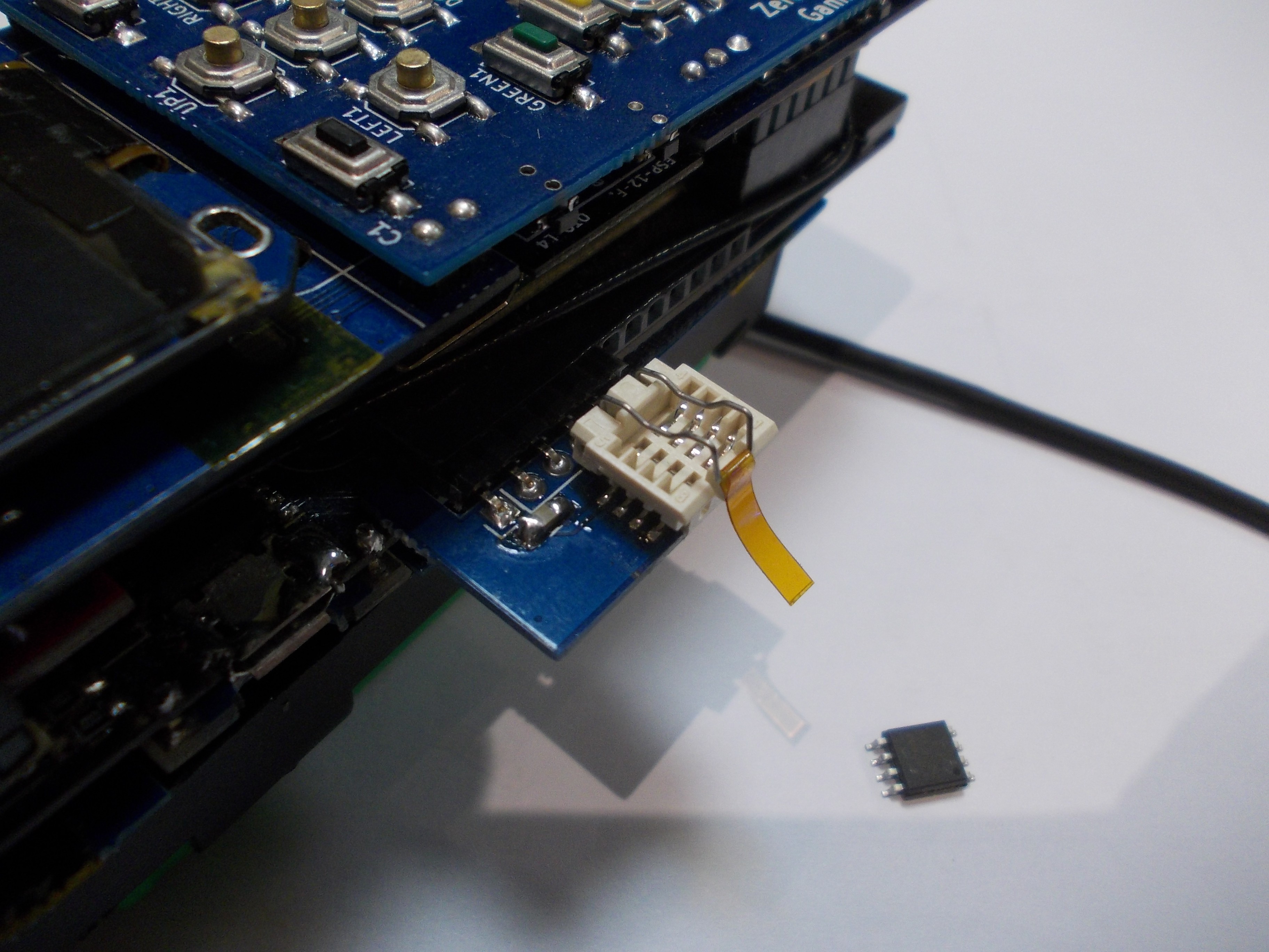
With this kind of sockets, you don't need to do any soldering when you're working with the chip, apart from needing to desolder it from and solder it to the target board (say, your laptop's motherboard) - you can simply insert the chip into the socket on the mod board. And, if you get one more socket and solder it onto the target board, there's absolutely no soldering necessary from that point - unplug the chip from socket on the target board, insert into a socket on the SPI flash board, flash new firmware, unplug chip and plug it into the target board. To be honest, I can't wait to demo it once the working version of this board arrives.
![]()
![]()
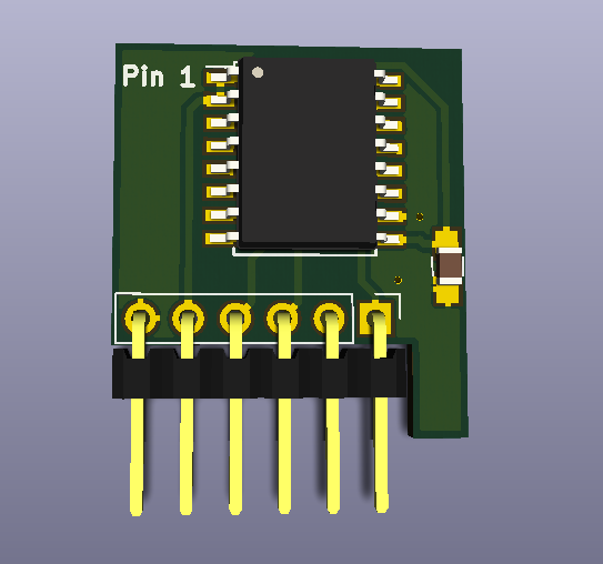
Some laptops (for example, one model of Thinkpads I've encountered while helping with a Libreboot install) have a 16-pin SPI flash chip instead of a 8-pin one. I've also found those same ZIF sockets for 16-pin flash chips - so, those are going to be included in the crowdfunding as well =)
![]()
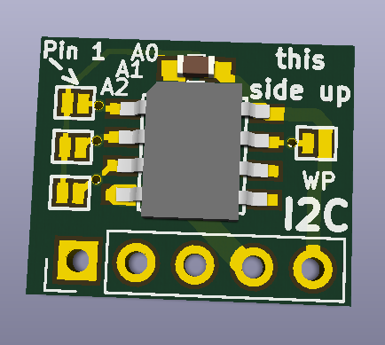
There's also a board for working with I2C EEPROMs, widely used for storing configuration parameters in various devices - for example, computer monitors use these to store information about supported resolutions (and make it accessible to the graphics card).
This trio of boards is a good set of boards for various hardware hacking purposes. Any ideas on more boards for hardware hacking?
GitHub link - 8-pin SPI flash adapter
GitHub link - 16-pin SPI flash adapter
GitHub link - I2C EEPROM adapter
These are only some of the mod boards - there are also the 3G modem board, the ENC28J60 Ethernet adapter, some boards to fit into the ESP-12 slot (that's likely going to be free on Zero W-based ZeroPhones), I just wanted to show some examples. If you have any mod board ideas, let me know in the comments, or email me, all that =) -
How to actually make money from ZeroPhones? (a.k.a business plan)
07/24/2017 at 13:02 • 1 commentSo, Hackaday Prize Best Product category requirements require a "business plan" - I have one hour till the deadline when it needs to be published ;-) But, incidentally, profitability is what I've been thinking this year - even though I love working on this, sometimes I still have to get distracted to side projects just to pay bills and buy hardware I need for this project (and there are always some unexpected expenses, like me spilling tea on my laptop last month). Making and selling hardware is the usual way for open-source hardware&software projects to bring some revenue. However, I imagine that with ZeroPhone, it's going to be a little more tricky than that.
See, ZeroPhone software is open-source, hardware is open-source, parts are really easy to get - there's literally nothing stopping somebody from copying this project if it becomes popular enough, and selling hardware on their own. Furthermore, people are encouraged to assemble their own ZeroPhones - this is kind of the whole point of this project!
So, when there's reasearch and development to be funded, there are contests/giveaways/bug bounties to be organized - how to get money for those, when the project's IP is open-source?
The most likely starting point for me will be selling ZeroPhone boards with SMD components already on, as well as ZeroPhone kits. For many people, SMD components are still out-of-reach in terms of skill (though, in most cases, it's just that they haven't tried ;-P ). As SMD assembly is much easier for manufacturing, selling PCBs with SMD parts already on would be pretty a low-hanging fruit in business terms. As for kits - this is maybe the most obvious idea, and I might just start first experiments with this one in a couple of weeks =)
However, as I already mentioned in some worklogs, judging by the survey responses, it seems like most people won't self-assemble ZeroPhones, but instead would like to buy pre-assembled ones. It's perfectly reasonable, and I should have expected this kind of statistic before - though I'm still figuring out how it'll work with the whole "manufacturing" thing. So, that's one source of revenue - ZeroPhone assembly services. While $50 is OK as BOM cost, it certainly doesn't cover assembly and testing, when it's done by somebody else.
Then, mod boards. ZeroPhone is extensible, it has extension ports, for which you can develop ZeroPhone add-on boards - for example, my favourite is a SPI flash programming add-on. Of course, you can still use a breadboard and some jumper wires, but just inserting a PCB into a socket is so much quicker and easier. The mod boards are supposed to be open-source, of course, but, in contrast to the ZeroPhone itself, they're not meant to be easy to assemble, or have easy-to-source components - mod boards are not essential to functioning of the phone, after all. So, you can have a mod board with an I2S microphone that absolutely needs reflow soldering with some low-temperature solder, or a mod board with an obscure IR transmitter/receiver, or even some BGA chips, and you are free to sell them to an existing market of ZeroPhone users that want this or that capability for their ZeroPhone - like, an Ethernet socket =)
Also, there's the "production-optimized ZeroPhones" idea. Basically, a version of ZeroPhone that's optimized for manufacturing instead of self-assembly - and, as a side effect, is smaller, consumes less power, has some additional functionality and might even cost less - but, more importantly, it's much easier to assemble and test those. Granted, they'll be less repairable - but still repairable (being fully open-source), and hardware will likely remain modular, though unlikely in a way that current ZeroPhones are. So, if assembly of ZeroPhones will be too hard of a task for large-scale assembly, this will be the option to pursue.
Last but not least, there's the "ZeroPhone customization services". While unlikely to be very popular, and also unlikely to be as formal as it sounds, there's still a market for it, I'm sure - especially given that current ZeroPhone is modular, so if you have some additional requirements for ZeroPhone hardware that can't be covered by mod boards, you can also get by without redesigning the whole phone, but only one of PCBs - be it a front PCB, back PCB or even a GSM modem PCBs.
One more obvious idea is, of course, re-selling ZeroPhone parts, While there'll be self-assembly tutorials on ZeroPhone Wiki, there's still way to add value - that is, buy parts from Chinese vendors, test them to see that they're the right ones and work well, then sell them to people that don't want the hassle of sourcing parts from different vendors and risking getting some parts that are DOA. . Furthermore, ZeroPhone parts can be sold to people that break some part of a ZeroPhone (say, snap one of the boards in half, or damage the screen) - possibly, with a discount if the person sends the broken part back, for it to be refurbished.
Is that good enough of a business plan? Well, it's mostly about selling hardware - with that, the devil is in the details, as usual, but in general it's a tried and true way to stay afloat.
-
Developing a simple UPnP/SSDP scan app
07/21/2017 at 22:10 • 0 commentsI'm sorry for the lack of code highlighting, especially given that it's crucial in this worklog. It seems to be some kind of Hackaday.io glitch - I hope it'll get fixed soon.
Sometimes, I find interesting articles that explain various network security concepts in a simple way. This week, I've found an article (in Russian, but the part that the snippet is based on is available in English) about UPnP and botnets, with some Python code snippets - and I've decided to build an app around those snippets. As I've built it now, I'm going to describe my app writing workflow - while I still remember it =)
First, SSH into my ZeroPhone and try this snippet (from the article in Russian):
#!/usr/bin/env python2
import socket
import sys
dst = "239.255.255.250"
if len(sys.argv) > 1:
    dst = sys.argv[1]
st = "upnp:rootdevice"
if len(sys.argv) > 2:
    st = sys.argv[2]
msg = [
    'M-SEARCH * HTTP/1.1',
    'Host:239.255.255.250:1900',
    'ST:%s' % (st,),
    'Man:"ssdp:discover"',
    'MX:1',
    '']
s = socket.socket(socket.AF_INET, socket.SOCK_DGRAM, socket.IPPROTO_UDP)
s.settimeout(10)
s.sendto('\r\n'.join(msg), (dst, 1900) )
while True:
    try:
        data, addr = s.recvfrom(32*1024)
    except socket.timeout:
        break
    print "[+] %s\n%s" % (addr, data)
It works and prints stuff! Furthermore, it can be tweaked - the most tweakable value seems to be the timeout value, as that's effectively how long the "scanning" part will be running. Let's convert it into a simple app!
---------- more ----------I like to take existing not-yet-bloated apps as a base for new apps - it's a simple "cp apps/old/ apps/new/" The most suitable app for this seems to be the I2C device scan app - also a snippet that I wrapped into an app =) For day-to-day development, I use tmux - it's very convenient to have dual panes, one with script being edited, one with shell where I run the script.
I'm still running an active SSH session into a ZeroPhone - I'll make it fullscreen, it's easier that way. First, I cd into main pyLCI directory - for me, it's in /root/pyLCI, later on it's probably going to be in /home/pi/pyLCI. Then, I launch tmux, split into two panes vertically - enough to be a good workspace!
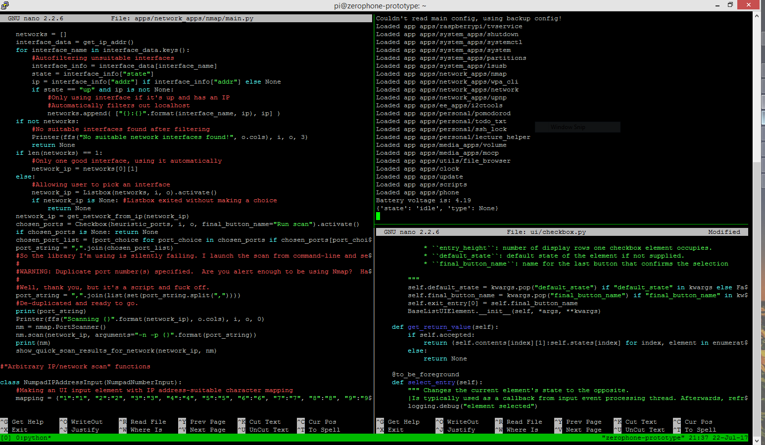
![]()
My layout while debugging a small checkbox label-related bug - two nano windows and running code, all in one window
Networking-related apps (even apps that can help with network pentesting) are, for now, stored in apps/network_apps/ directory. So, I create a new directory there - apps/network_apps/nmap. Then, I copy main.py from I2C scan app into that directory, and create an empty __init__.py. Now, if we were to launch it right now, it'd be absolutely the same as I2C scan app - because the code is the same, we just copied it over =) Now, time to edit the code - but first, what are the requirements?
- "Scan" button, which triggers scan, then displays the results
- Timeout needs to be adjustable through the UI. pyLCI has a suitable UI element for that - IntegerAdjustInput, which lets you increment/decrement an integer using "up" and "down" keys.
- Timeout, if set to a custom value, needs to persist between pyLCI launches - so we'll use a config file.
First thing I usually do is defining the app menu contents. It helps me understand what are the user-exposed functions, how are they linked together, and thus helps me understand the structure of the app:
main_menu_contents = [
["Scan", run_scan],
["Change timeout", adjust_timeout]
]
App starts with a menu, so the "callback" function will look like this:
def callback():
    Menu(main_menu_contents, i, o, "UPnP/SSDP app menu").activate()
What remains is to write "run_scan" and "adjust_timeout" - simple, right? =) Let's start with "adjust_timeout" - it should take value from the config that's currently loaded, let user adjust it and save the updated config back to the config file:
def adjust_timeout():
    global config
    timeout = IntegerAdjustInput(config["timeout"], i, o, message="Socket timeout:").activate()
    if timeout is not None and timeout > 0:
        config["timeout"] = timeout
        write_config(config, config_path)
Our app is not class-based, so we're using a global variable for config storage. I like to use dictionaries for configs, and pack them into JSON - coincidentally, pyLCI offers two functions, read_config(path) and write_config(config, path), that work on JSON-encoded data structures in files.
Now, we need to write something that actually loads the config file. I believe it should be safe to do this as the app is imported, right after the import statements. We need to figure out the correct location relative to the app folder, so that it doesn't load the main "config.json" (with input and output device definitions), but an app-specific one. It's basically boilerplate code, soI published some code snippets on the ZeroPhone Wiki - just copy-paste them into the app =) Also, it has a snippet that detects if config file is missing/malformed - I'll use that one, too, I can just copy-paste it and get some failsafe functionality =)
current_module_path = os.path.dirname(sys.modules[__name__].__file__)
config_filename = "config.json"
default_config = '{"timeout":1,"dst":"239.255.255.250","st":"upnp:rootdevice"}'
config_path = os.path.join(current_module_path, config_filename)
try:
    config = read_config(config_path)
except (ValueError, IOError):
    print("{}: broken/nonexistent config, restoring with defaults...".format(menu_name))
    with open(config_path, "w") as f:
        f.write(default_config)
    config = read_config(config_path)
The "run_scan" function is the only one left. The first part is the same as in the Python script I'm re-making, but I add a Printer() - notice that it runs for 0 seconds, basically, printing text on display and exiting - this is for user-friendliness, so that user knows what the app is doing right now =) Also, some parameters are taken from config, of course - not all of them are editable from the UI, but at least they're changeable using the config file.
def run_scan():
    Printer("Scanning:", i, o, 0)
    msg = [
        'M-SEARCH * HTTP/1.1',
        'Host:{}:1900'.format(config["dst"]),
        'ST:{}'.format(config["st"]),
        'Man:"ssdp:discover"',
        'MX:1',
        '']
    s = socket.socket(socket.AF_INET, socket.SOCK_DGRAM, socket.IPPROTO_UDP)
    s.settimeout(config["timeout"])
    s.sendto('\r\n'.join(msg), (config["dst"], 1900) )
Then, let's actually scan the devices. To store scan results, I add an OrderedDict - it feels more user-friendly to output requests in the same order they were received. Also, I print tracebacks any exceptions that were received that aren't socket timeout exceptions - logging would be a better idea, but for now there isn't a well-defined pyLCI-wide logging facility - so logging will be added once the support is there. Address is also received as a (string, int) tuple (IP, port) - but it only really makes sense to store it as a string, so it's converted to one.
    found_devices = OrderedDict()
    while True:
        try:
            data, addr = s.recvfrom(32*1024)
        except socket.timeout:
            break
        except:
            print(format_exc())
        else:
            ip_str = "{}:{}".format(*addr)
            found_devices[ip_str] = data
The last part is outputting values to screen. Responses are received as multiple-line HTTP-like requests, and only relatively small part of a request is useful. So, for now it makes sense to just show IPs to the user, and show full request contents if user wants to see them. There's certainly some more useful data in responses that could be displayed, but it'd require parsing the responses - this app was literally written in half an hour's time, so I didn't really think of that as a feature - guess that's a TODO =)
So, I get a list of IPs and I have to show them to user, so that user could click on one, see data, go back, click on another one, see data for that IP - that's a job for a Menu. There's a very similar Listbox UI element that could be used, but it returns immediately when the value is selected, so it's not suitable for this task (you'd implement, say, audio channel selector with a Listbox, but audio settings menu with a Menu.). Right now, each IP address will take one row of characters on screen - if I decide to add more data to the IP view (like, get device make and model from response), I can use entry_height attribute of Menu to be able to show two and more rows of data for each Menu entry.
For menu, you need a list of two-element lists, where first element will be entry representation on the screen, and second element will be a function that'll be called when entry is selected (callback). I like to write small generators for that:
    if not found_devices:
        Printer("No devices found", i, o, 2)
    else:
        data = [[ip, lambda x=ip, y=d: read_info(x, y)] for ip, d in found_devices.iteritems()]
        Menu(data, i, o).activate()
I have one function, and it needs to be called with different arguments, depending on the entry selected - that's a job for lambdas =) Notice the x= , y= trick - lambdas do not create namespaces and don't store values which are passed as arguments, so I have to "store" them this way. Then, I construct a Menu and pass control to it on the spot - that's where user gets the list of IPs on the screen. What's in the read_info function?
def read_info(ip_str, data):
    print("[+] {}\n{}".format(ip_str, data))
    Printer(ffs("[+] {}\n{}".format(ip_str, data), o.cols), i, o, 5)
It simply shows the request to the user (in the same format that the original snippet did), printing it to console (as a side effect, will remove soon). Notice the ffs("long string with linebreaks", o.cols) - it takes a string and makes a list suitable for on-screen output, splitting it by words where possible and marking linebreaks with empty on-screen lines. I actually think there should be a PrettyPrinter, basically a Printer(ffs(data, ...)...) - maybe I'll do it in spare time (can somebody do it earlier?).
There's this bad thing - there isn't yet an UI element for reading a block of text without interruptions. Printer UI element will eventually exit on its own - after all the screens pass by. I set timeout for each screen to be 5 seconds, but it can easily not be enough for a slow reader, and it isn't as user-friendly anyway. So, such an UI element is in the TODO.
This is pretty much it! We have a working app - it scans for UPnP/SSDP devices and shows any responses it gets. Of course, it's not complete- as of now, it needs some more things to be more useful:
- Saving full and individual scan results into files in app folder when some key is pressed - like NMap app already does. I don't think this feature will be useful enough to be a snippet in the wiki, but I can pretty much copy-paste the related code from the NMap app and have this functionality.
- Handle more errors, for example, when network is not available, when socket can't be opened, maybe even handle malformed responses - there will be a lot of ground to cover once this is tried on different devices.
- Once UI element for reading blocks of text appears, use it instead of Printer
- Add error logging - to some file
- Parse responses and show useful parts in the IP overview
Here are links to the app code - this is the commit I made today, and this is current version of the app at any point of time. Something else?
Give your feedback in the comments, try this app on your network (it's not ZeroPhone-specific, so will work on your Linux PC with a pyLCI emulator), send bug reports and pull requests - all that stuff =) I hope that this writeup will be useful as a tutorial, giving you insights into how to write apps, as well as into decisions involved in making a user-friendly and useful ZeroPhone app.
-
Hardware worklog: display problems understood
07/18/2017 at 03:25 • 10 commentsWhen I was sourcing parts off Taobao, I ordered wrong display breakouts. They looked just like the ones I was supposed to buy, with two small differences - GND was swapped with VCC, and pin header had RST instead of CS. First problem caused me to burned a panel or two, second problem made me waste a week or two of my time. Here's how it goes:
The ZeroPhone has expansion ports. In particular, there's a 13-pin expansion port on the side, with SPI-0 port on 4 of them. SPI is a really popular communication standard, you can use it to re-program BIOS chips, ATMega/ATTiny/other Atmel chips, show things on LCD/OLED/E-Ink displays, communicate with SD cards, RFID readers, thermocouple amplifiers, GPIO expanders... I have designed two mod boards for this exact headers, and I wanted to include them in the package sent to reviewers and contributors - because I believe it's important to show that ZeroPhone also has tools that make hardware experimentation easier.
SPI uses the CS pin to signal, which peripheral it currently wants to communicate to. SPI-0 on the Pi has 2 CS lines - one goes to the display header, another goes to the expansion header. If, however, the display doesn't have the CS line exposed, then there's no way to signal to the display that it's not supposed to receive information at this point when, for example, there's an RFID reader on the expansion port. The result will be, at best, garbage shown on the display - at worst, the display might interpret commands sent to RFID reader as commands for the display, and it might even damage the display.
So, just re-wiring the breakouts, swapping RST with CS, should be easy? After lots of broken panels and wasted time, I understood this wouldn't be the case.
![]()
First idea was to cut out the RESET signal from the OLED panel FPC and short CS signal to the pad that RESET pad of the FPC was supposed to connect to. However, it turned out that CS pad was shorted to ground - and the trace couldn't be cut, because it was on the section of breakout PCB that was under the flex cable. Oops. I decided to disassemble all the displays, that is - unglue the OLED panel and desolder the panel FPC from each board, then set panels aside and work on modding the PCBs. Panels were desoldered (with 1 or 2 lost to "broken panel edge" problem) and left on a table at the hackerspace. In a couple of days I went to collect them to put them all aside, only to find that, apparently, somebody has dropped something heavy on them, breaking 5 panels. Oops. Lesson learned, I guess.
This is not the safest place, either, but at least nobody will touch them there - this table is occupied by me and only me.![]()
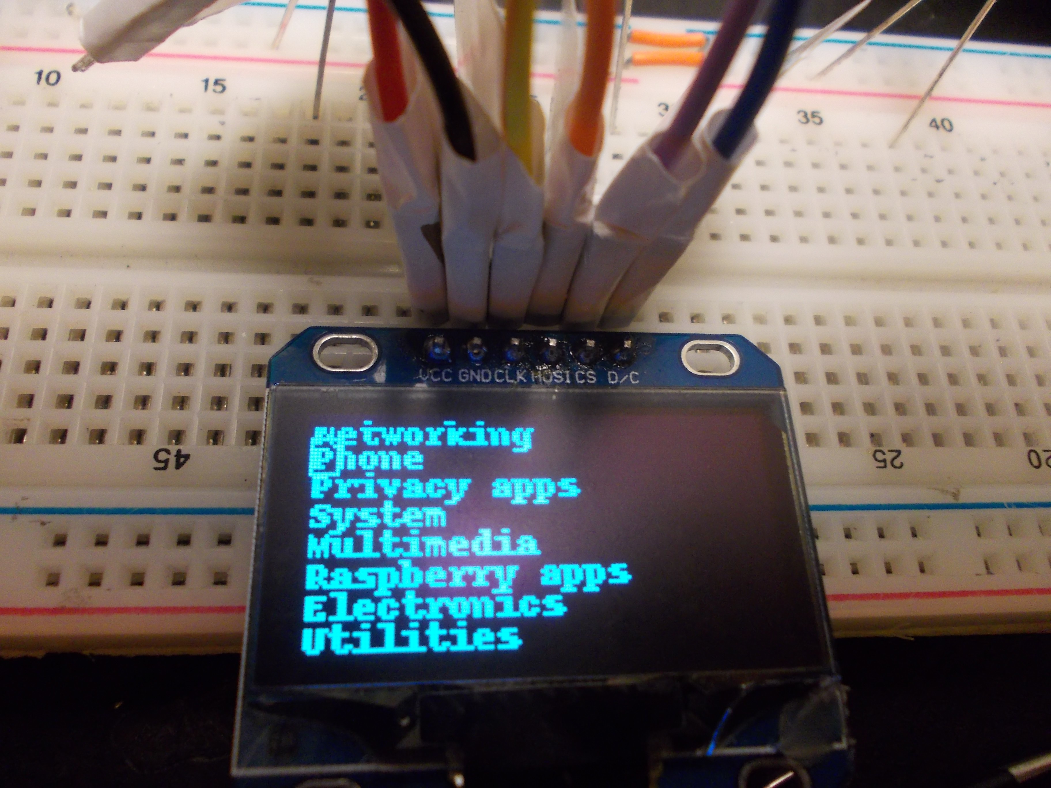
As I got the panels separated from breakouts, I could try putting panels on 7-pin breakout PCBs I had, which have both RST and CS available. They worked, so the panels were, supposedly, similar - the difference must have been in the breakouts. I didn't have enough 7-pin breakouts, and they don't fit the ZeroPhone that well anyway (they're kinda ugly and have oversized outlines), so I had to get the CS signal on the 6-pin breakouts I got.
Next idea was to cut both "CS-GND" and "RST-header" traces and re-wire them so that they'd be "RST-pullup" and "CS-header". X-acto knife, magnet wire and some resistors did the job electrically, but it didn't work, either. At this point, I wasn't even sure that there wasn't a chance that there was something wrong with my Pi (given that it, apparently, survived some negative voltage on SPI, because I accidentally swapped polarity when connecting displays, at least a couple of times by then). I got one more sacrificial Pi Zero and checked with it - it still didn't work.
The breakouts are kind of ugly from the back, IMO =(![]()
I experimented with the displays some more, adding and removing pullups. It wouldn't work, no matter what I added. I tried to connect a 7-pin display - it would work with RST signal, but the re-initialization procedure wouldn't go through again if RST signal was removed. Could it be the luma.oled library? It does get updated, after all, and they do consider RST to be a have-to-connect pin, so it might just be that the library used to send a soft-reset code but it got deleted in the next release... Something was fishy.
Today, I recalled I still had one display which had a 6-pin header with CS and no RST.
However, dramatic music, in order to get to it, I had to disassemble the first ZeroPhone that I assembled. The one that started it all, had to go, so that I could move further with the project. I found it and started the disassembly, almost with tears in my eyes.
*flashbacks*
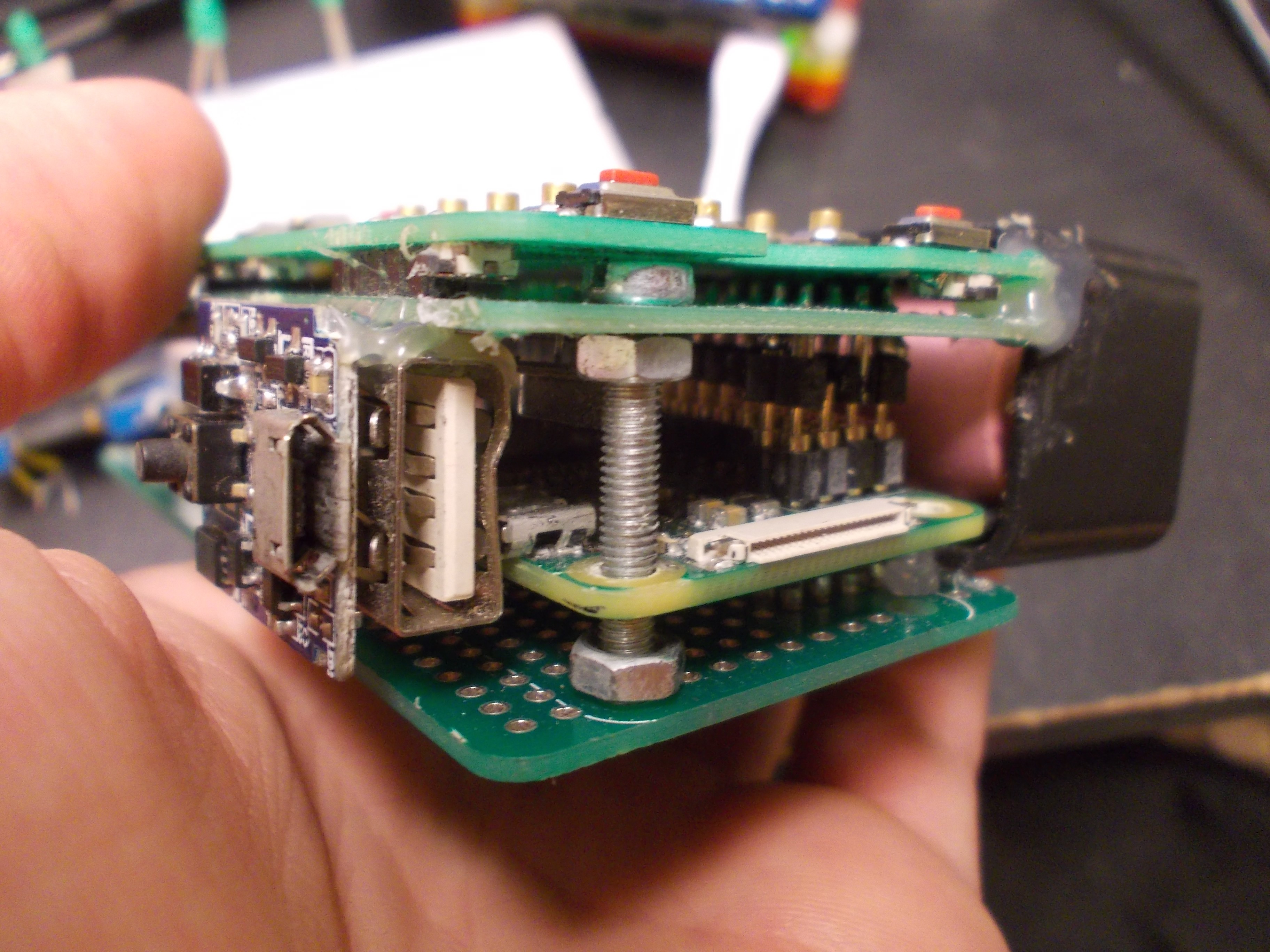
I did have quite some mechanical issues with the first prototype, due to the use of machined headers - while they're great and make good contact, they are short and so mechanically the phone would just snap in two pieces from time to time. Thus, the screw - and three nuts on it, even. Also, LiIon charging&protection&5V boost circuit salvaged from a powerbank - the powerbank itself glued on the side of this contraption. Truly horrible design, but hey, 100K people saw its photo, and most of them kind of liked it... Okay, they liked the idea, not the looks of it =D =D![]()
GSM modem has non-0.1 pitch between header rows, so I had to do "castellations" of sorts. There's also the first SDIO design I did - I remember being super nervous about it, and I remember just sitting down and re-doing the first layout version, that, I'm sure by now, was horrible - the traces were all over the board. I'm glad to have people that can give advice in my life - I sat down with a guy in horu hackerspace, he spent at least an hour criticising the board, but he basically set me straight in a lot of things =) Mind you, the alpha boards still turned out horrible, but nothing of that horror was something he could foresee. Also, magnet wire fixes!![]()
When designing audio circuit, I basically said "fuck it", put some testpoints and decided I'd figure something out. I did, but it was tricky - this picture actually has 1) scraped off soldermask 2) deadbug soldering 3) kapton tape 4) magnet wires - the holy quartet of bugfixing. Next revision was better - though still shitty, no doubts.![]()
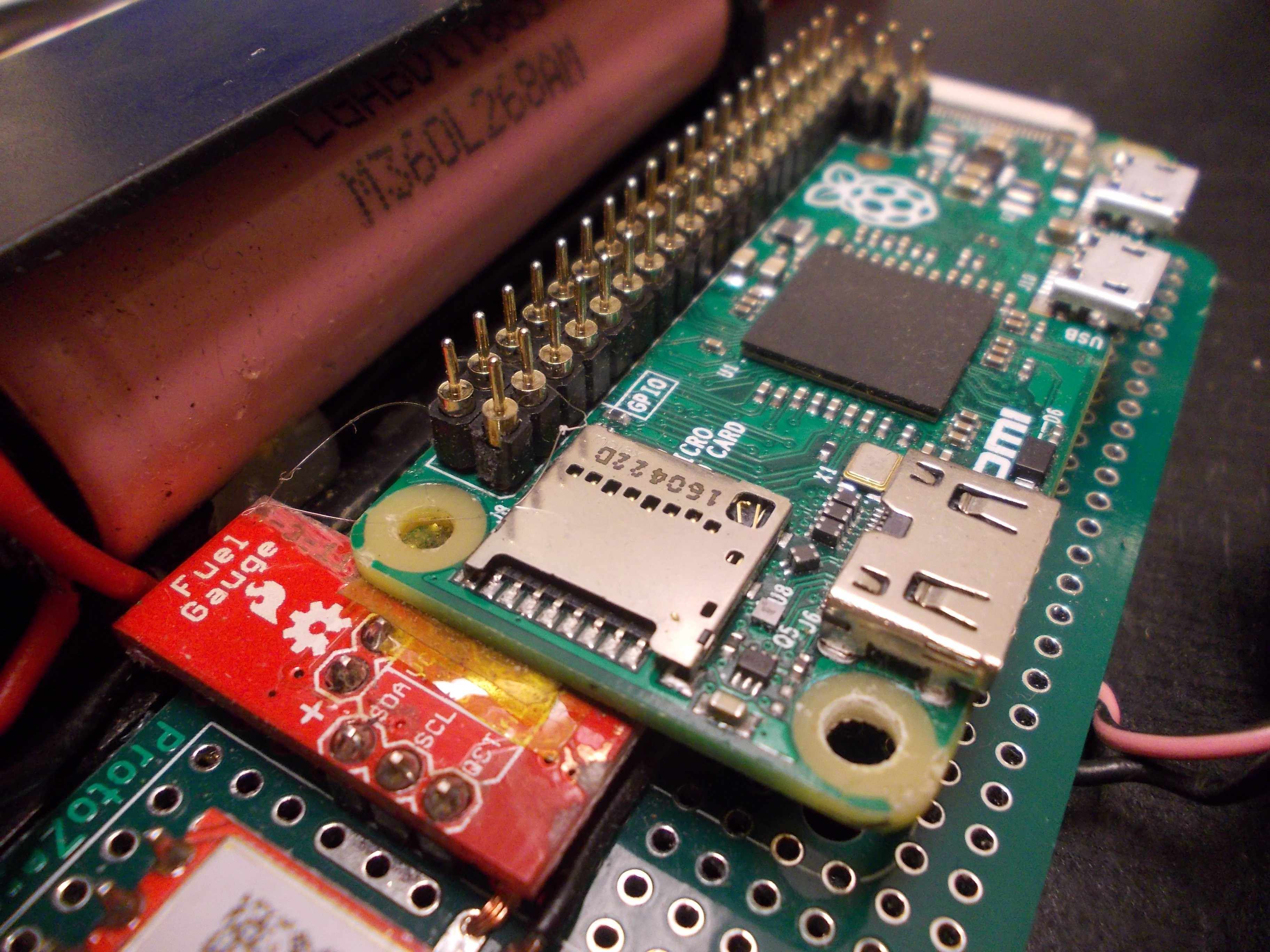
The fuel gauge chip breakout, MAX17043. I did collect some data from it while this prototype was being used, but I think that data turned out to be nearly useless in the end. =(![]()
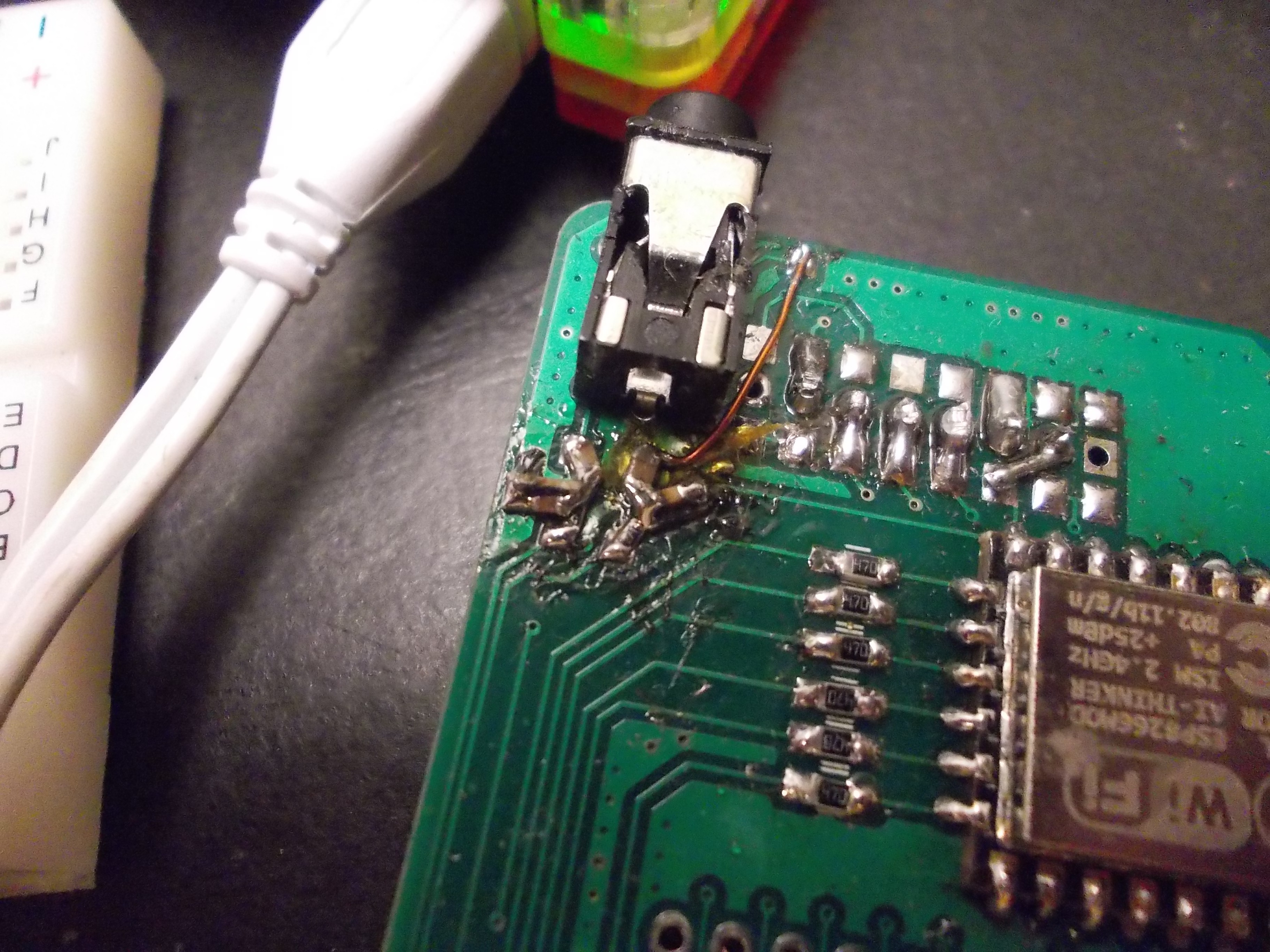
I wiped the tears off my face, desoldered the display and looked on the back of the PCB.
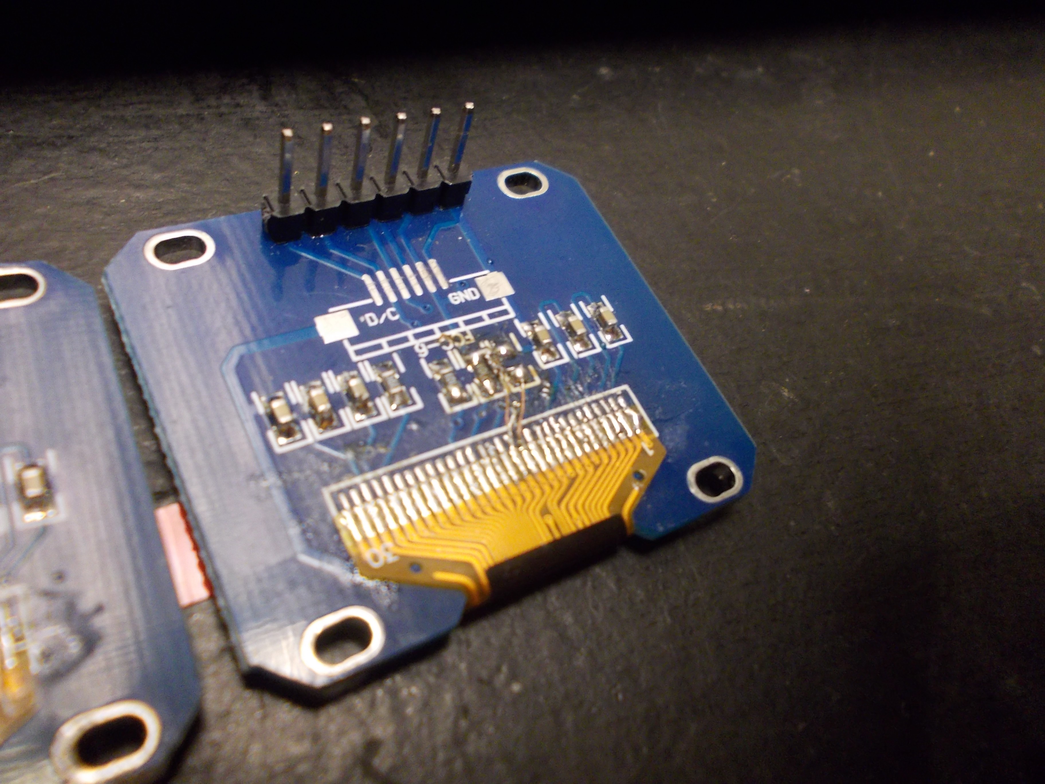
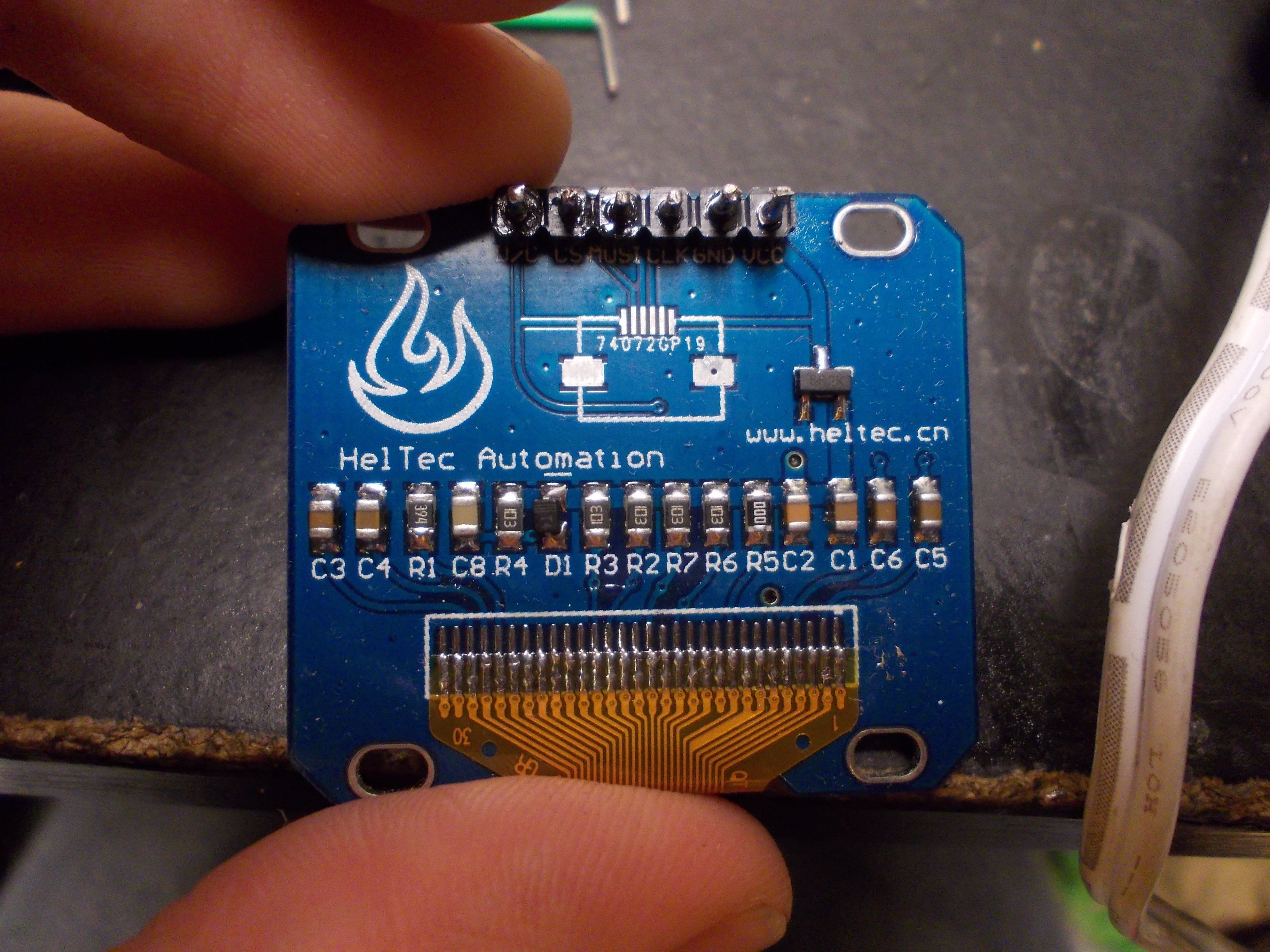
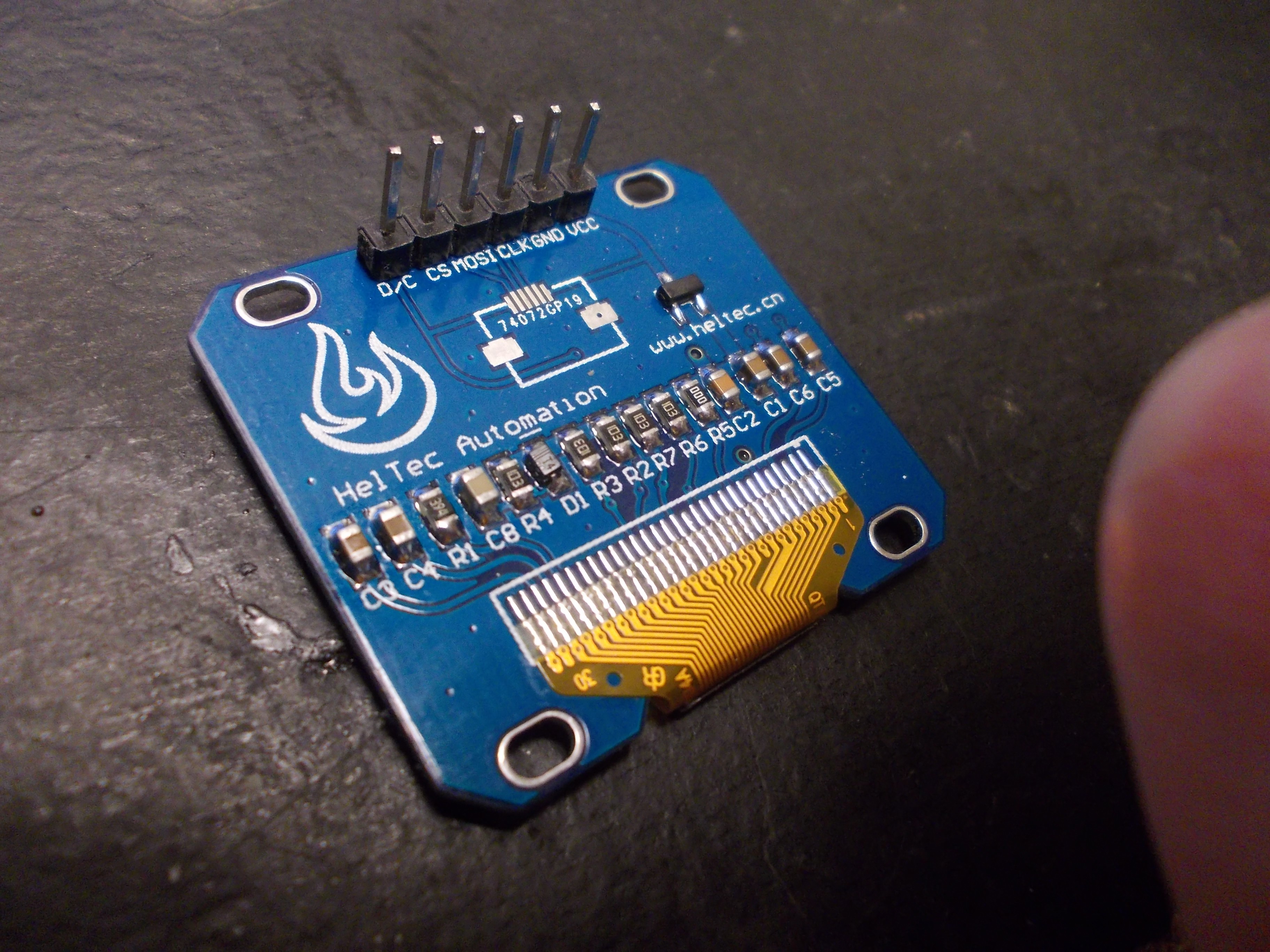
Now, this is interesting. A diode (haven't really seen those on OLED breakouts before), and much more components than I anticipated, too. BTW, the routing is really pretty. Let's solder some new headers and check:![]()
Just the right image, no RST required (c).![]()
What would it be? Where does the RST signal go? On the first glance, nowhere. On the second glance, though...
C8-R4-D1 combo is a RC circuit, apparently. I intuitively understand the way it works. but I'll be checking all the connections in-depth, too. My understanding of this solution is - it slowly drives the RESET line from low to high once power is applied to the display, so that the hardware reset occurs at least once - which seems to be enough.See the C8 capacitor - it's a different color than all the others! In my experience, this means that its value is different, too. That will have to be measured as soon as I'll be sourcing parts for the display breakouts that I, it seems, will have to order. BTW, talking about the new breakouts - I'd totally steal this design, it's just so pretty, with all the curved lines - I just wish KiCad could do this =)![]()
Now, pretty much the only display-related trouble left is figuring out the importance of a voltage regulator on the display breakouts. In theory, the displays should be OK with 3.3V, which is currently the voltage available on the headers - but I know that at least one display behaved in a weird way after removing the regulator and shorting its VIN to VOUT.
This is how a big ZeroPhone trouble finally ends. This is not the end of "problems to be solved ASAP", though - there's this mysterious noise in the GSM audio lines, and I swear it wasn't there on the beta boards... To be continued.
Also, I still have to make a video, at least a short one. However, I'm quite sleepy by now so this will have to do.
-
Project state - boards to be tested, Hackaday Prize, project plans
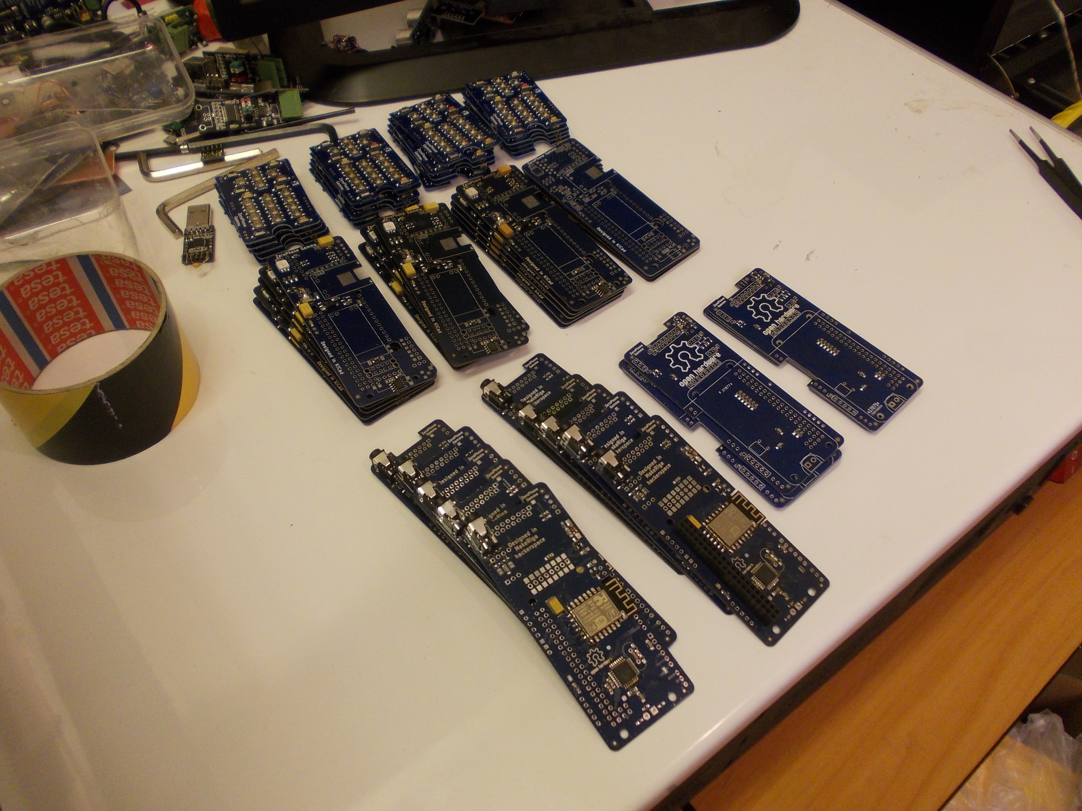
06/21/2017 at 06:31 • 2 commentsA new version of ZeroPhone is being in-field tested right now, and the batch of 20 ZeroPhones is almost built - I'll be testing it now.
![]()
Boards in stacks of 5. I ran out of some passives to finish the boards in the bottom left corner, but I'll have them tomorrow.
The boards pictured are already checked visually, no visible soldering bridges or misplaced components (there were a lot of those). Now they just need some THT stuff attached - that will need lots of human intervention, but I've found some people that can help with it, tomorrow and the day after =) Also, hey, at least I seem to have all the THT parts I need and don't need to run around sourcing them.
![]()
We won $1000 in Hackaday Prize! That was really unexpected, I mean, we aren't even IoT - though I do have some really cool IoT-related features in my mind =) I think that this is going to be an awesome opportunity to upgrade the tools I've been using for ZeroPhone assembly - so that less time is wasted the next time I'll be building a batch of ZeroPhones. For a start, I'll upgrade the pick&place and the "reflow" oven I've used - it's never been intended to be used for PCB reflow, so it can't do thermal profiles or anything like that, and you need to supervise it to turn it off at the right time. Then, I'll also make a small stash of spare components, from those that are the hardest to get here - like, some reels of passives that local shops no longer have (because I've bought them all and they don't want to order new reels yet), displays and GSM modules and whatever has shown to be harder to get than anticipated. Having some spare components is also great for helping out other ZeroPhone users - if somebody somewhere has a broken component, I can ship out a new one on a short notice!
There's a need for an FAQ of the project, for a project roadmap document, and for a document that'd serve as a list of contribution priorities. I'm slowly drafting something here (for the software part, but there'll also be at least the "hardware" part), and this is the document that, I hope, will work for all three of those needs.
This month was busy. I've spent a lot of time trying to make the Pick&Place work, and I haven't succeeded with that in the end, so I had to pick&place all the components myself. Then, I ran into sourcing issues, some decisions that I needed to make on the spot, some more random tools I needed to get... Sufficient to say, all the bad decisions I've made and the problems I've encountered do deserve a separate worklog, and I hope that things I've learned this month will help me make better decisions in the future.
As for now - as soon as I finally ship the prototypes, I'll work on estimating the financial part of the project, no doubt, the most important part when it comes to crowdfunding, so it has to be done first in order to understand how I can price it realistically, what I can offer, what are the changes I'll need to make and what are the possible problems I'll encounter.
Next thing to cover this week - current state of hardware. Cheers!
-
Project state - assembling ZeroPhones!
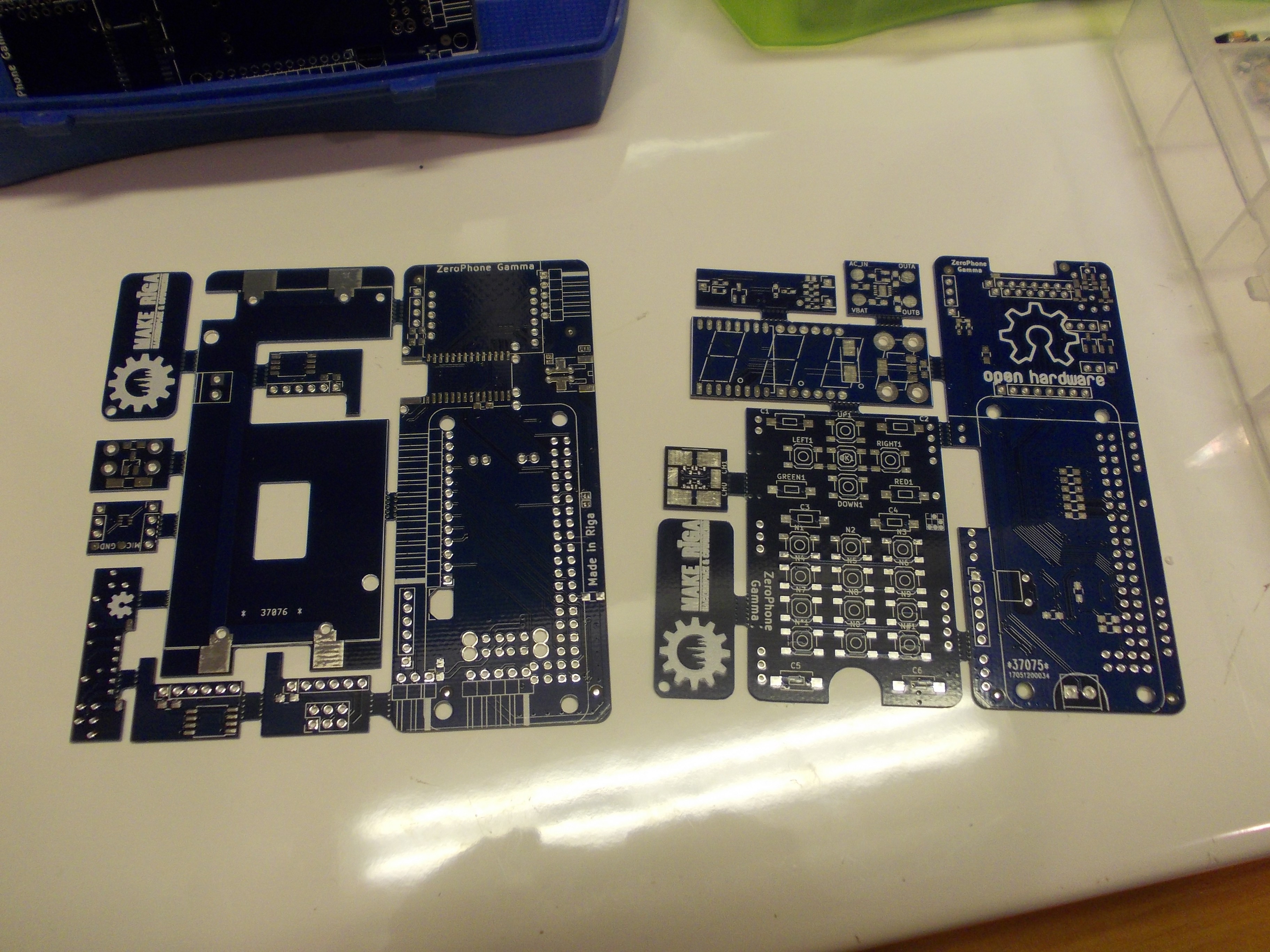
05/28/2017 at 17:20 • 2 commentsSo, I got the Gamma boards, panelized, 22 front&keypad board panels and 24 back&18650 board panels, all from DirtyPCBs:
![]()
I also got lots of passives and actives, headphone jacks, all that, it seems I have all the parts necessary for ZeroPhone assembly. BTW, if you want to learn to panelize the boards like this, I got a tutorial for you =)
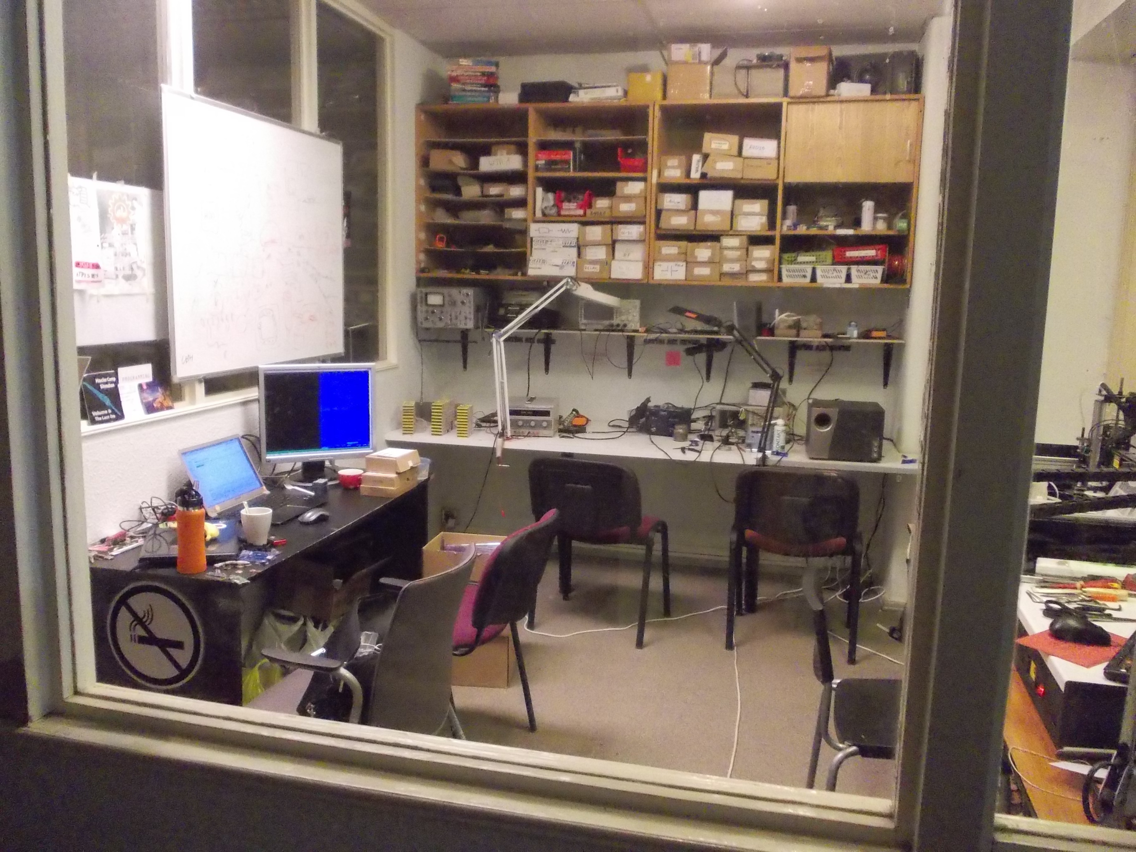
I also took over a separate room in our hackerspace:
![]()
This room has the Pick&Place machine, which is the main reason I'm now working there - I'm trying to make this Pick&Place assemble the boards I want it to assemble. So far, my efforts have been extensive but not very successful - I have both software and hardware problems, and I might as well miss the "ship ZeroPhones to USA this Thursday" deadline if I don't solve them tomorrow =(
![]()
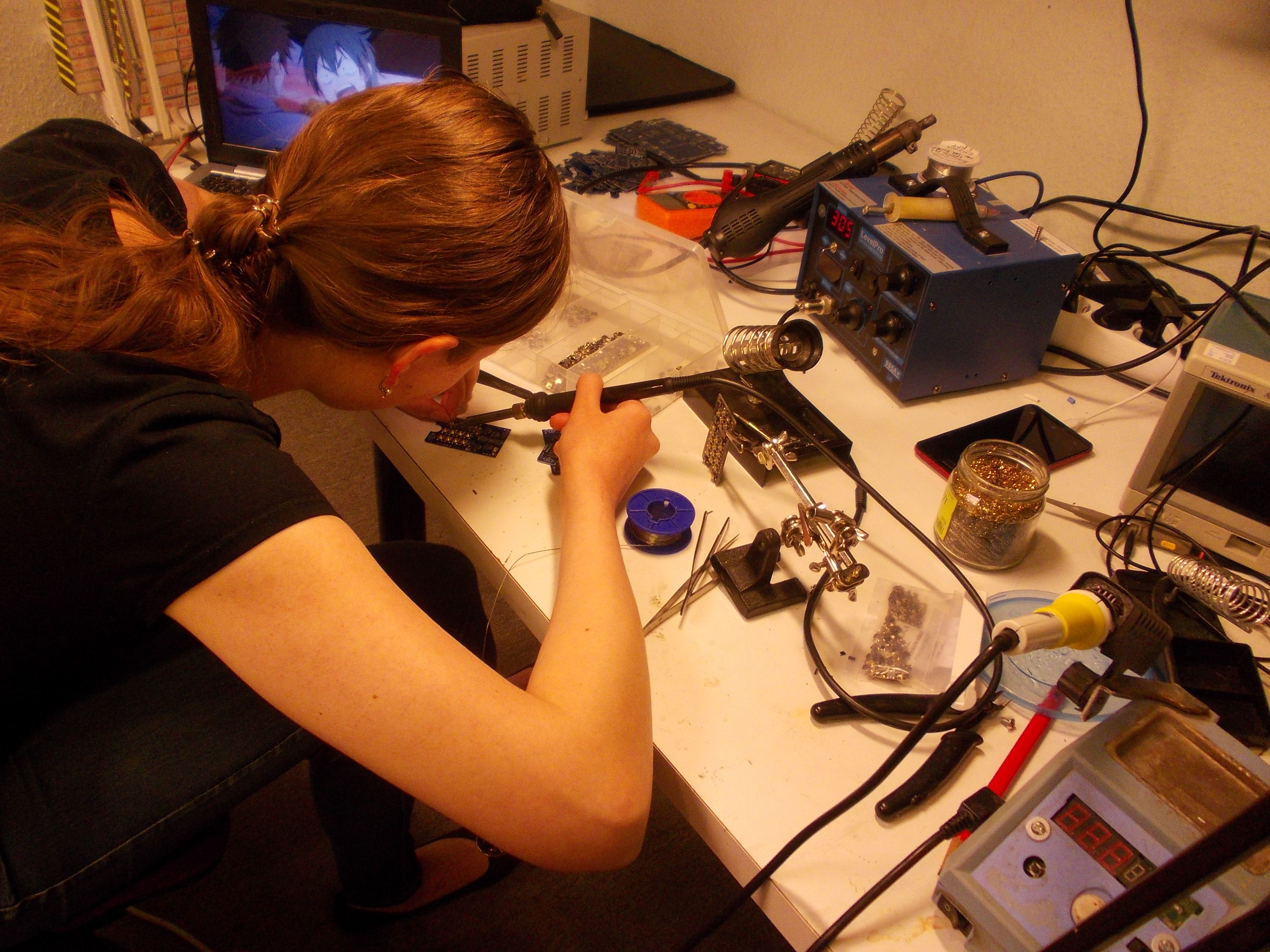
For where the normal pick&place won't be able to help, I got some help from my wife:
![]()
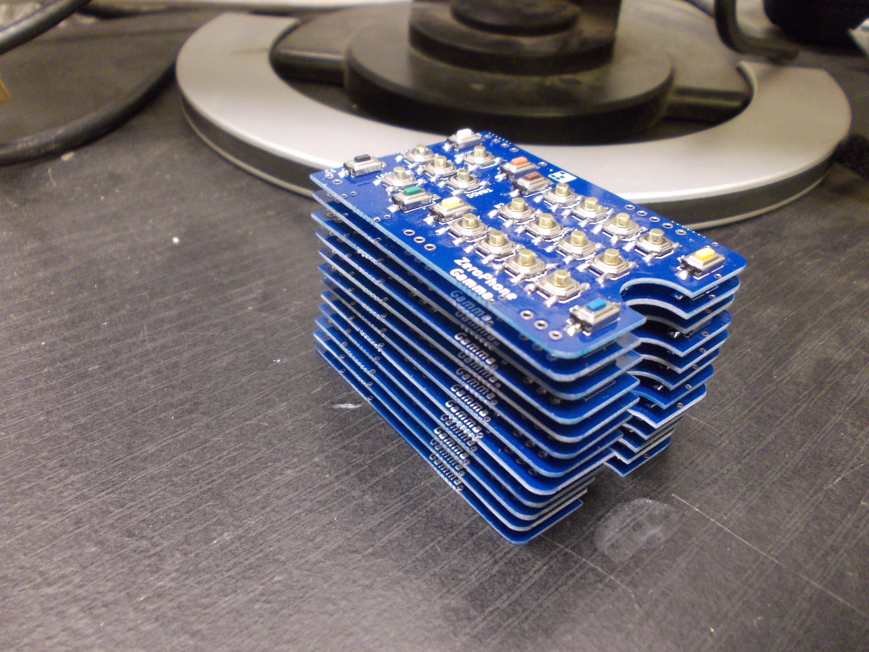
So far, she's assembled this beautiful stack of keypad boards:
![]()
But, unfortunately, we still won't be able to assemble everything without a Pick&Place. Oh well, will be continuing my Pick&Place journey tomorrow. Anybody has some LitePlacer setup experience?
There are a lot of things to be moved to Wiki, they deserve their own separate worklog and I will be writing that the next week. The most important thing - I'll be making a rolling "project state" page on ZeroPhone Wiki, as well as post the project schedule and project plans there.
Of course, there are problems at this stage:
- Display breakout problem - worst case, I'll be forced to design my own display breakout boards and wait for them from China =(
- Money problem - I'm out of money at this point, I'll have to find about 150EUR for shipping ZeroPhones to USA by DHL (because normal postal services just aren't acceptable for that).
- Packaging problem - I need to think of some kind of packaging for ZeroPhones - some kind of tailored cardboard box for each one, ideally, just like phones are typically sold. I do have a laser cutter, and I could buy some cardboard sheets, but I don't have any box design, and I don't have any experience designing boxes either.
- I need to assemble one Gamma ZeroPhone now, then I need to make a video about ZeroPhone assembly, and I need some instructions about it on Wiki.
So, next week (starting tomorrow), I'll be solving these problems, while setting up a PnP, assembling ZeroPhones and working with contributions - sounds like lots of fun! =D
This is what a tape of 100 SOT-23 FETs looks like - a 32x28cm flat foil envelope with the cut tape rolling inside among some small silicagel bags. Generous! =) Cheers to TME!![]()
-
On volatility of Chinese breakouts; "production-ready" ZeroPhones
05/28/2017 at 16:15 • 1 commentAs I mentioned earlier, ZeroPhone is basically a PCB sandwich. Now, ZeroPhone consists of three custom boards, a Pi Zero and 5 Chinese breakouts:
- ESP-12 board
- SIM800-based modem board
- 1.3" OLED breakout
- Li-Ion charging circuit
- Step-up DC-DC board (generates 5V for USB port)
All of these boards, except (very popular) ESP-12 breakouts, can change. Reasons are - Chinese optimize those breakouts all the time (decreasing BOM count and/or PCB size), want to add features to innovate (consequently, to raise price), and, I think, sometimes just copy the pinouts and board outlines from one another, re-tracing the board.
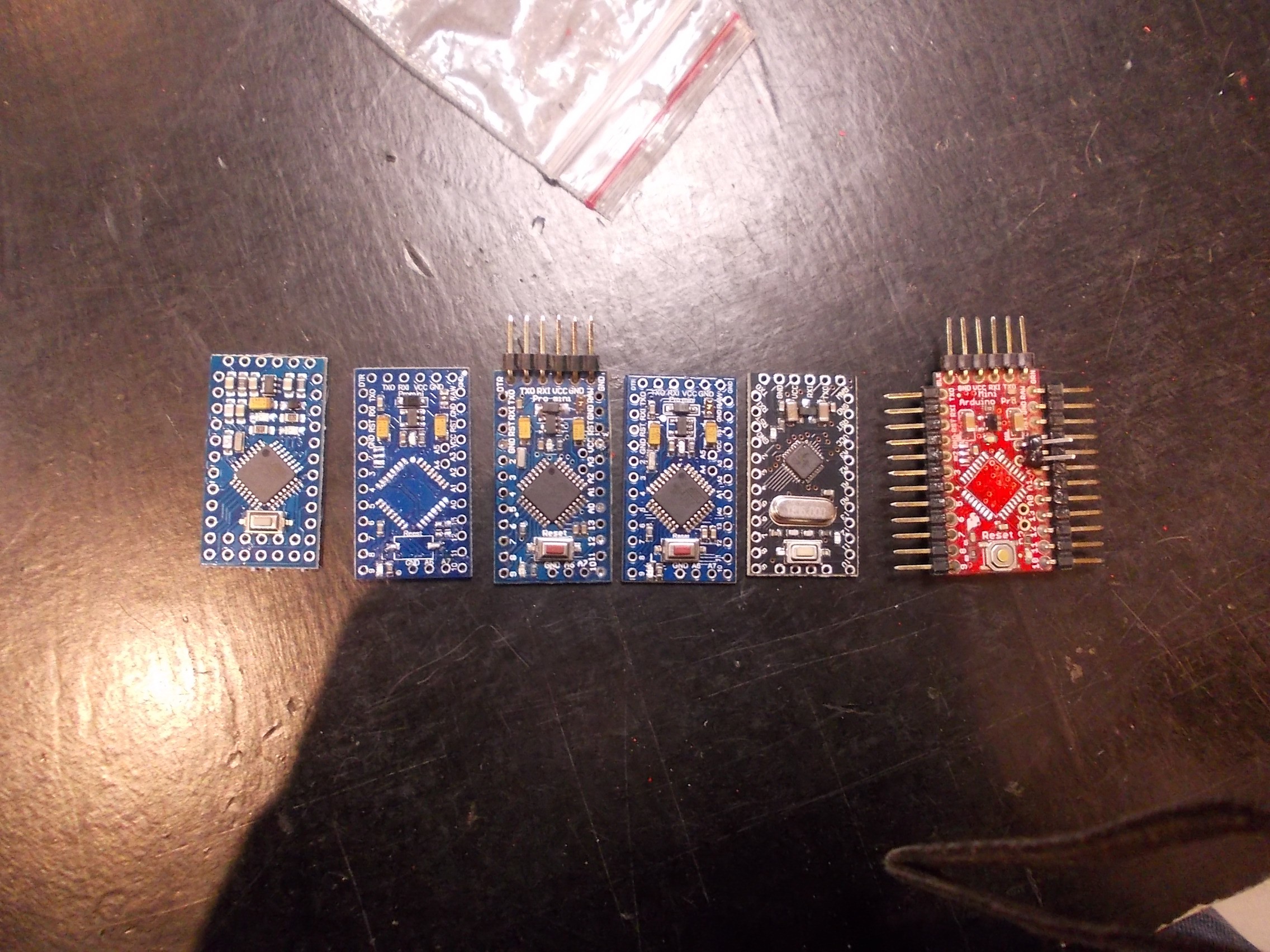
For example, here are photos of different Arduino Pro Mini clone PCBs I have:
![]()
Some of them don't look different, but the traces are all routed differently, and some differences are easy to spot from this photo - such as holes changing places. And that's only what I have currently, I've used and seen much more different boards.
They went through these revisions in a couple of years, and it was mostly moving components around, but pinouts also changed - mostly A4-A7 pins. If you're designing a shield for Pro Minis (for easier assembly and user-friendliness) and it uses I2C, tough luck with sourcing boards.
I'm assembling a batch of 20 prototypes now, as you can rememember, and I got the components for them. However, those components weren't what I expected.
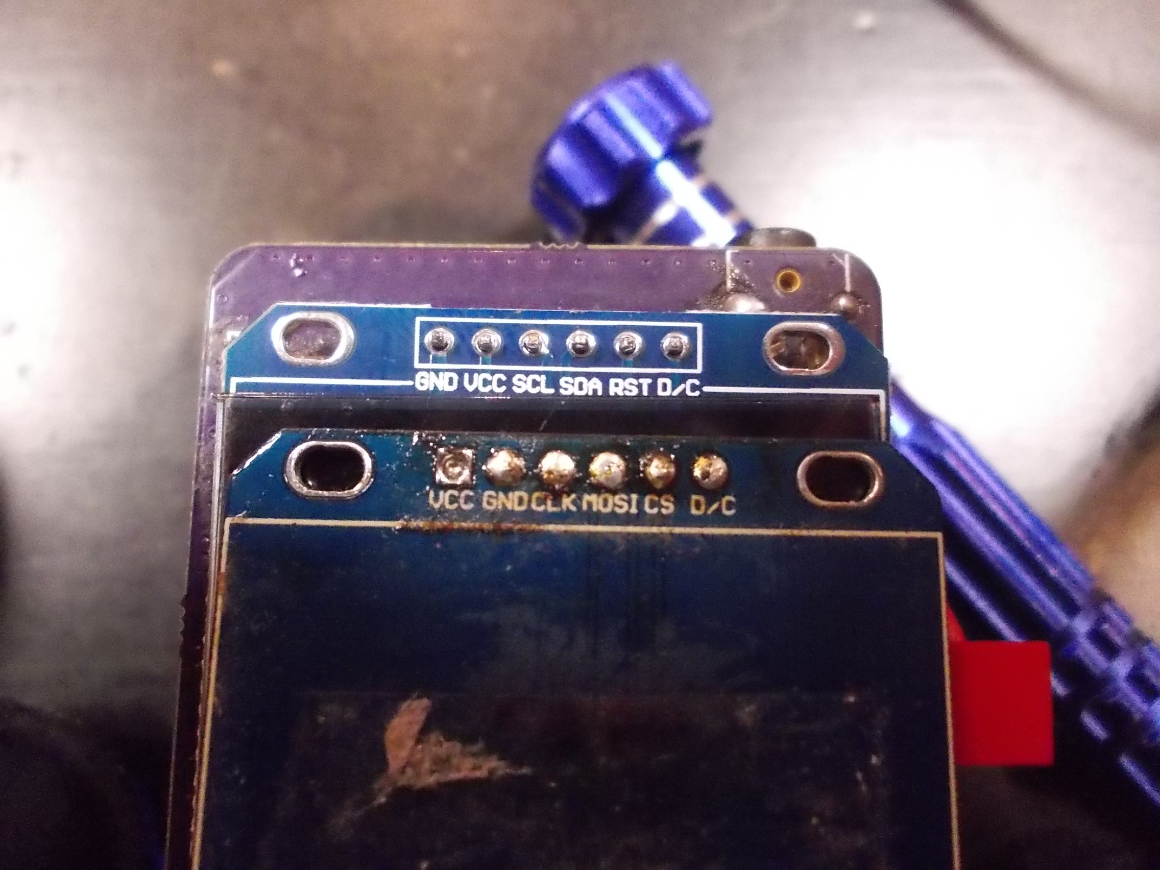
![]()
Check out those two screens. The pinout changed, and in a bad way - the first display I connected just burned out because GND and VCC were swapped (I'm glad that SPI survived). However, this is not the problem - my multiple-pinout header takes care of that. The largest problem is lack of CS pin. It means that the SPI bus can't really be shared between the screen and the expansion header - the expansion header that's supposed to work with ZeroPhone addons. The other displays I've been using are all OK, and I'm sure that if I bought other displays, they wouldn't have been as braindead. To be honest, I should have looked more closely at the display breakout the Chinese seller listed - it does show the pinout on the photo. =(
Seems like that lack of CS pin is only the problem for the *cheapest* breakouts out there. Seems like somebody made quite a bunch of them, and now is trying to sell them as cheaply as possible - multiple TaoBao sellers have those.
Talking about this small batch, there's certainly a way to fix the display breakout - however, I still haven't found it. Whatever the fix is, it's going to involve some manual work with the PCB - not meant for production, and, as the fixes I've attempted so far have failed, I'm going to need to experiment with it tomorrow.
What more, the LiIon charger breakouts I got are also screwed up.
![]()
Top breakout is the "normal" breakout I've been using for years now. Bottom breakout is the one I got from TaoBao. It does take less PCB space, yeah, but the MicroUSB connector is shifted in a way that wouldn't fit on normal boards .
![]()
How many "normal" breakouts I have, vs how many "screwed" breakouts I have
I haven't had ordered the gamma boards at the time when I received the breakouts, so I quickly made a redesign of the gamma boards - I thought I couldn't really risk ordering more breakouts and receiving the screwed-up ones again. Now I think I was mistaken - I should have ordered the normal boards from eBay once again, two-three weeks from the moment I got the breakouts wouldn't be that unreasonable, since I would have had gotten them the beginning of this week. What more, I think I'll have to revert the changes - I had to move the breakout footprint on the Gamma boards, as a result, it's now mostly compatible with those changed boards - not so much with the "normal" boards, they stick out of the outline =( However, what if I revert the changes and then the "normal" breakout will fade away from Chinese sellers?
To sum up, the charger boards are not as much of a PITA as display boards are, and Gamma ZeroPhone assembly won't be interrupted by those - but I'll need to revert the changes and avoid using these breakouts again.
I've been told about this kind of problem before. The reason I'm now bringing it up because it started affecting ZeroPhone, and we need to do something about it. I'll be thinking and researching about ways on how to avoid it when producing ZeroPhones, and for now my lesson is "Be very careful when ordering breakouts". I should also refrain from doing quick changes to boards - I think that I should make sure the breakouts *actually won't be available anymore* before adapting the boards to a new version of breakouts (unless I'm forking the boards for a side project, then anything goes).
Production-optimized ZeroPhones
One more important idea I'll be working on is production-optimized ZeroPhones. The hacker-friendly PCBs are here to stay and will be maintained and upgraded, but not everybody actually needs hardware-hacker-friendliness. What's are the differences for the production-optimized version?
- 4-layer boards - with proper power planes and better routing possibilities
- Smaller SMD packages - for both chips and passives (still using parts that can be easily sourced)
- Using OLED panels, ICs, SMD GSM modules and connectors instead of relying on breakouts
- Possibly, merging the keypad and front boards
As a result, the production-optimized version will have considerably less risks associated with its production, availability of components and possible mistakes that can be made during production. It will still have extension ports, full software compatibility and be open-source hardware, of course!
This could help make ZeroPhones cheaper, smaller and less power-consuming, as well as somewhat more capable. This could open ZeroPhone to a huge market of people who just want a Linux smartphone but don't want to work with hardware (many survey responses talk about this), and it would make the ZeroPhone much more reliable for those people.
More importantly, it makes manufacturing much, much less error-prone, and this is a very important factor that will help once I take responsibility for manufacturing ZeroPhones in more or less large quantities. I'll still be crowdfunding the hacker-friendly version this year, but it's possible I'll start crowdfunding of production-optimized ZeroPhones by the end of 2017. I'll further outline production-ready ZeroPhone version here before I start working on it, so stay tuned =)
As always, will be glad to hear your thoughts in comments/over email!
-
Hardware switches and new discoveries ("paranoia worklog")
05/24/2017 at 05:07 • 0 commentsLet's talk about hardware switches, advertising profiles and side-channel leaks. ZeroPhone is different from many smartphones in that the GSM baseband is separate from the CPU, so there's no proprietary code running on the CPU that comes from the GSM modem manufacturer. The communications happen through UART and are controlled by and directed through open-source software.
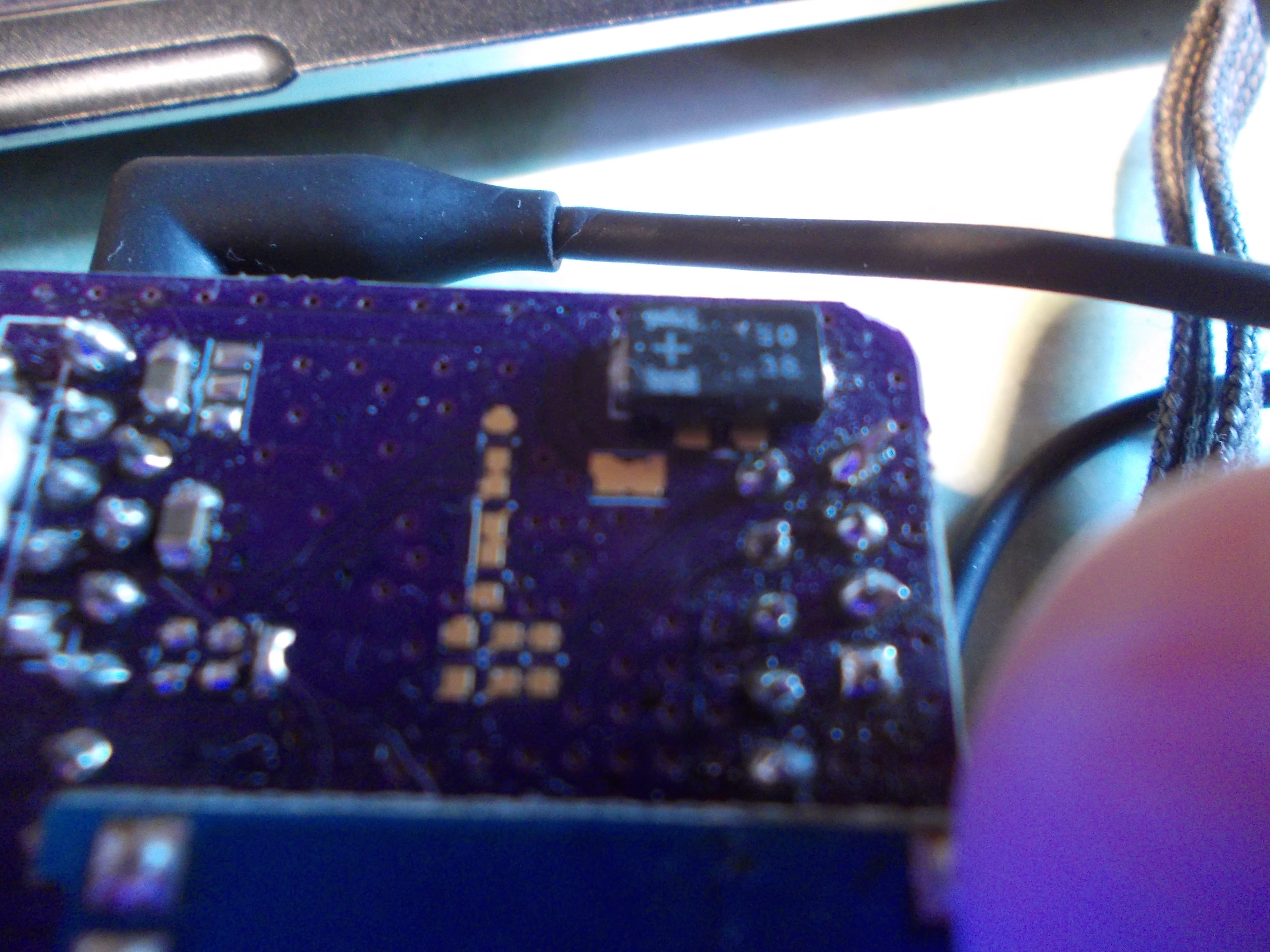
I sometimes got questions about hardware switches. It's a niche but nice feature - not only it's the ultimate power consumption decreasing mechanism, it's also a way to ensure the radio-enabled components can't work when you absolutely don't want them to work - for privacy and safety. ZeroPhone is using off-the-shelf GSM modules - and they have an inner CPU which runs some kind of firmware, and that firmware running on the modem can make it transmit, even though you might not be telling it to transmit. We can implement software kill switches, but maybe the software itself is going to have bugs? The simplest and most powerful "just make sure it's off" hack is cutting the VCC line to the modem, ensuring it doesn't work at all and thus doesn't have the ability to transmit when you want it turned off.
One more reason for that - what if the GSM modem firmware is malicious? We don't know, SimCom doesn't provide much of source code and SDKs, and one of the modem batches they send out could be programmed with a firmware that's slightly different from the widely-used firmware, with some *extra features*. Can we *trust* the modem? No, not really.
The jumper pad is the exposed copper right under the big black capacitor. Its positioning is less awkward on the new boards I'm about to receive =)![]()
So, current ZeroPhone boards have solder jumper pinouts. Those solder jumpers are shorted by default, but you can cut them and solder a switch to the pads, so you could interrupt power to some peripherals. Currently, the only peripheral that has a jumper is SIM800 modem, though - it's the only peripheral it actually makes sense to limit. The ESP-12 that is used for WiFi (though is entirely optional) can also have this kind of switches, but I didn't add them because of routing difficulties - the power track is in the center of the front board. Furthermore, we control the CH_PD GPIO on ESP-12 module anyway, so we can enable/disable the ESP8266 inside by holding the GPIO low or high, both reducing the power consumption and making sure there can be no transmissions (I guess we could also wire a FET in parallel to that signal, just to be sure).
However, there are still problems with the power cutting approach. People usually will still keep the GSM modem powered on because they will actually want to stay accessible to others, to be able to receive calls, SMSs and whatnot. Even when not expecting any calls, or even not wanting to receive any, many people will forget that. So, the advantage of cutting power may be lost - this is a problem, and one that could possibly be solved by using reminders, GSM activity monitoring... Or maybe, even geolocation - basically, trading off privacy for privacy. =D
There's also this thing that keeps popping up once in a while (and it was mentioned in ZeroPhone survey responses a few times) - "using speakers as microphones, and vice-versa". While it works physically, I assume that even the proof-of-concepts would mostly affect the chipsets on modern x86 motherboards, where audio is re-routable from path to path. Even then, I don't think it has a chance of going through amplifiers - so speakers are out of question (and headphone jacks might just have an amp hard-wired instead of having switching logic, though I'm not sure it's not always like that). Realistically, Van Eck phreaking is a much biger potential problem. Will we have speaker and microphone switches on ZeroPhone, though? Yes, see below.
There's a more important thing. It's more important because people haven't yet heard about it as much.
It appears that, in smartphones, app-embedded advertising can use smartphone speakers to transmit data that's modulated by ultrasound. that allow the advertising networks to merge advertising profiles from different devices. Advertising networks can target their advertising much better once they know which devices belong to which people. There's this obvious principle that says "if the devices are near each other most of the time, they probably belong to the same person". This is one of the methods you can use to make cell tower-based tracking easier, and it seems it's used by advertisers nowadays - with ultrasound.
Say, you have 2 phones, one is for private information and one is for work information. If an advertising network can link them together, with all the data they can collect on you from both phones, they can know more about you and target you better (in work matters, this could be disastrous for both you and your work). Also, let's say you install some free app on each smartphone - and it's possible you'll install free-as-in-beer app, with some kind of ad network bundled in. If you permit it to access your microphone, you'll never know when and what is it that it listens for.
The ad networks use two approaches. First - they use ultrasonic-range overlayed sound in TV transmissions, so that it's possible to both link devices (given the transmissions are unique each time, this is a matter of statistics), as well as know what you're watching. Second thing - they use permanently-installed beacons in locations like restaurants and shops, both as parts of customer loyalty programs and, I assume, for general data collection - I'm sure no data collected is ignored.
Of course, for that you need to have some apps installed, those that use the advertising networks that employ ultrasound-based tracking. Chances are you don't, but the technology seems to just start becoming popular, so we don't know where it takes us - and it's better to be cautious.
Some more information - the paper and some Google links
- The paper - released in 2017 (seems so from filename), but mentions of this technology can be dated even to 2016
- Hackaday.com - "ULTRASONIC TRACKING BEACONS RISING"
- "uXDT & Audio Beacons - Introduce your Paranoia to your Imagination"
- "Silently Tracking Users With Ultrasonic Beacons"
- "234 Android Applications Are Currently Using Ultrasonic Beacons to Track Users"
- The company that does this - Wikipedia
Talking more about ultrasound - what else is there that we don't know? Maybe some devices, even while not compromised, emit some kind of ultrasound tones due to their inner workings (say, inductors), and the compromised devices have some kind of profiles that link tones to devices? What if there could be such a profile for ZeroPhone? That wouldn't be the end of the world, but that would suck.
With Raspberry Pi audio done as it's done now - with PWM - there's background noise, and I guess that noise could have its own profile. So, if a ZeroPhone audio output is connected to some kind of speakers, it's possible that some software could determine its presence in the room (that's excluding the obvious "scan for Raspberry Pi MAC addresses" part.) Is it realistic? I don't know. Is it addressable? I think so, I should receive simple audio output filter PCBs tomorrow, so we'll see.
... Anybody interested in making a Pi-based spoof ultrasonic beacon that transmits garbage? =D
-
Project state - prototype batch will soon be built
05/10/2017 at 21:46 • 6 commentsComponents arrived, PCBs ordered
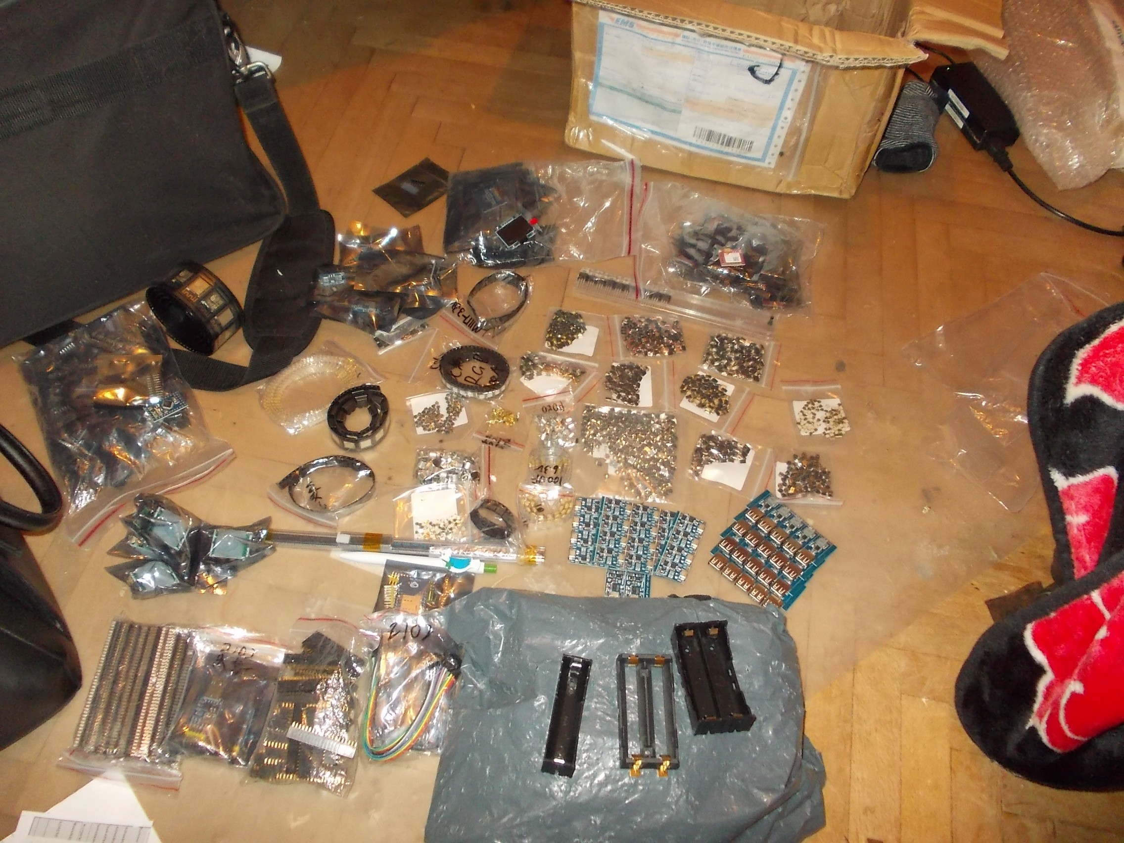
A week ago I received a box full of goodies:
![]()
Most of the parts pictured are ZeroPhone-specific, and some parts are either extras or parts I ordered for myself =) The bag in the bottom center is full of 18650 holders, all three models pictured. Tape with white squares are the coolest BIOS chip holders ever, that I was trying to find for ages until I finally did find them for very reasonable price on TaoBao. Next to the laptop bag you can see a tape of 50 ESP-12 modules, and the bag next to it is full of Arduino Pro Minis. Ziplock bags in the center, to the left, are full of pushbuttons - the biggest of those bags has 750 buttons, and the plastic tube has 30 MCP23017 ICs. And, of course, there are 25 screens and 20 GSM modules - the latter I didn't have problems with, but screens just keep breaking on me.
Today, after I made all the board corrections (mostly related to "components arrived and they're incompatible with boards I'e designed"), I've uploaded 2 different panels to DirtyPCBs - full of both ZeroPhone boards and my personal experiments.
![]()
![]()
ZeroPhones that I'll be sending out will consist of 4 boards:The Li-Ion board is for a simple reason, I still haven't decreased power consumption significantly and, while I'm going to turn off everything that I know affects power consumption, there's still a lot of what I know - that weird board with lots of exposed copper, right on top of the keychain on the front board, is voltage/current sensor breakout which is going to help me actually run benchmarks on power consumption.
There are also 3 mod boards:
- Audio buffer mod - to filter Pi Zero PWM audio output, making the sound less noisy (presumably, haven't tested it yet)
- SPI BIOS-like chip flashing board - for all kinds of BIOS experiments you'd want, without resorting to obscure Chinese BIOS flashing dongles
- ATMega ISP programming board - for easier experimentation with all sorts of ATMegas and ATTinys
![]() I have ideas for some more mod boards:
I have ideas for some more mod boards:- IR transmitter/receiver board - LIRC-compatible
- I2C EEPROM boards - for tinkering with various EEPROMs
- I2S audio mod board - to integrate Pi Zero and GSM audio together
- Audio amplifier add-on - for using small loudspeakers with Pi Zero PWM audio
As I already mentioned, the assembled ZeroPhones will be shipped to 1) reviewers, such as Hackaday, Crowdsupply etc. 2) project contributors and people who have pre-ordered ZeroPhones in order to start tinkering.
Now, after writing some more worklogs and answering all the emails, it's software time.
I do have two important questions:
- Do you have any mod board ideas?
- I have 5 ZeroPhones that can be sent to reviewers. Do you know of any bloggers/YouTubers who'd be interested in making a review of a ZeroPhone?
ZeroPhone - a Raspberry Pi smartphone
Pi Zero-based open-source mobile phone (that you can assemble for 50$ in parts)

 ZeroPhone is lacking in the "audio" part, compared to the smartphones we have: the audio on current smartphones is highly integrated (with lots of audio paths and some specialised ICs for switching them), and ZeroPhones are assembled from widely available parts, those two contradict each other. Currently, there's 1) GSM audio - speaker and microphone connected to the GSM modem, not accessible to the Pi Zero in any way 2) audio output from the Pi Zero on the 3.5mm jack, not accessible to the modem in any way. So, it's kind of limited - especially given that USB sound cards aren't really an option.
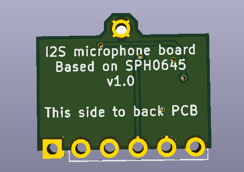


 I have ideas for some more mod boards: