Arya
Arya-
Hardware: alpha board testing jig
02/08/2017 at 05:43 • 0 commentsThis project interests many people. Many people asked questions and gave suggestions, some went as far as to contribute. Those people are interested to help me with various aspects of the project, and most of them will need hardware. So, I had to learn to assemble, test and ship things =) Assembly is simple, shipping is, too. Let's talk about testing the boards.
The boards go through e-test on the factory - to check for shorted or disconnected tracks. However, I still had to ship every board with an ATMega programmed, two traces cut and 5 magnet wires soldered to make new tracks. Furthermore, I literally emptied all my Arduino Pro Mini stash by this time and had to re-use ATMegas from Pro Mini boards harvested from my previous projects - some of them definitely had fried GPIOs, I just couldn't tell which ones. Also, same could be said about my ESP-12 module stash, I had to check every one I could harvest from somewhere, since I burned some of them - been recklessly driving motors and doing other horrible things with those.
Solder, something to watch and lots of patience![]()
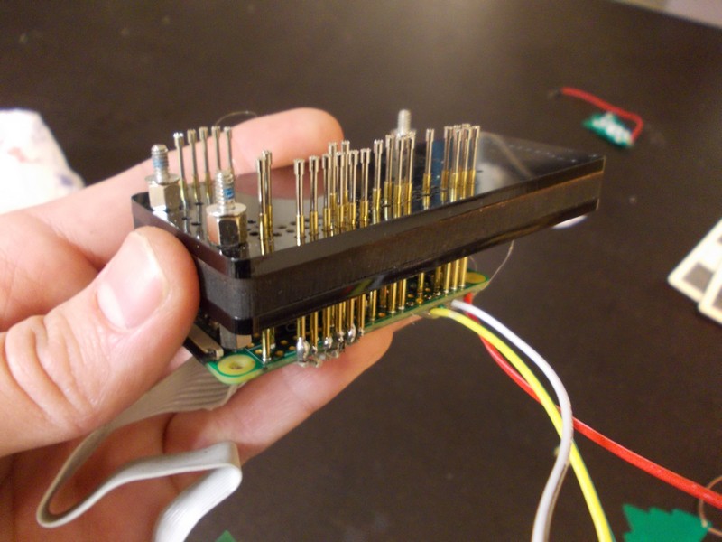
Thankfully, my hackerspace has a stash of pogopins - hard lessons learned after one of the members had to make a testing jig urgently, then had to pay 1$/pin from Farnell. Next best thing was that all the pads with necessary signals were through-hole. What that meant was I could just use the drill file from Gerber files and not export copper layers (like I would have to if I needed pogo-pins on some SMD pads). The workflow for me was as follows:
- Take the Gerber, open it in KiCad's Gerbv, deselect anything but outline and drill files
- Export it to SVG
- In Inkscape, remove unnnecessary holes, make uniform line thicknesses, adjust the hole sizes (so that pogopins would fit just right and not be loose)
- Export it to the hackerspace's laser cutter
- Cut, check, fix, repeat
![]()
Spoiler: three screws weren't enough, it'd bend.
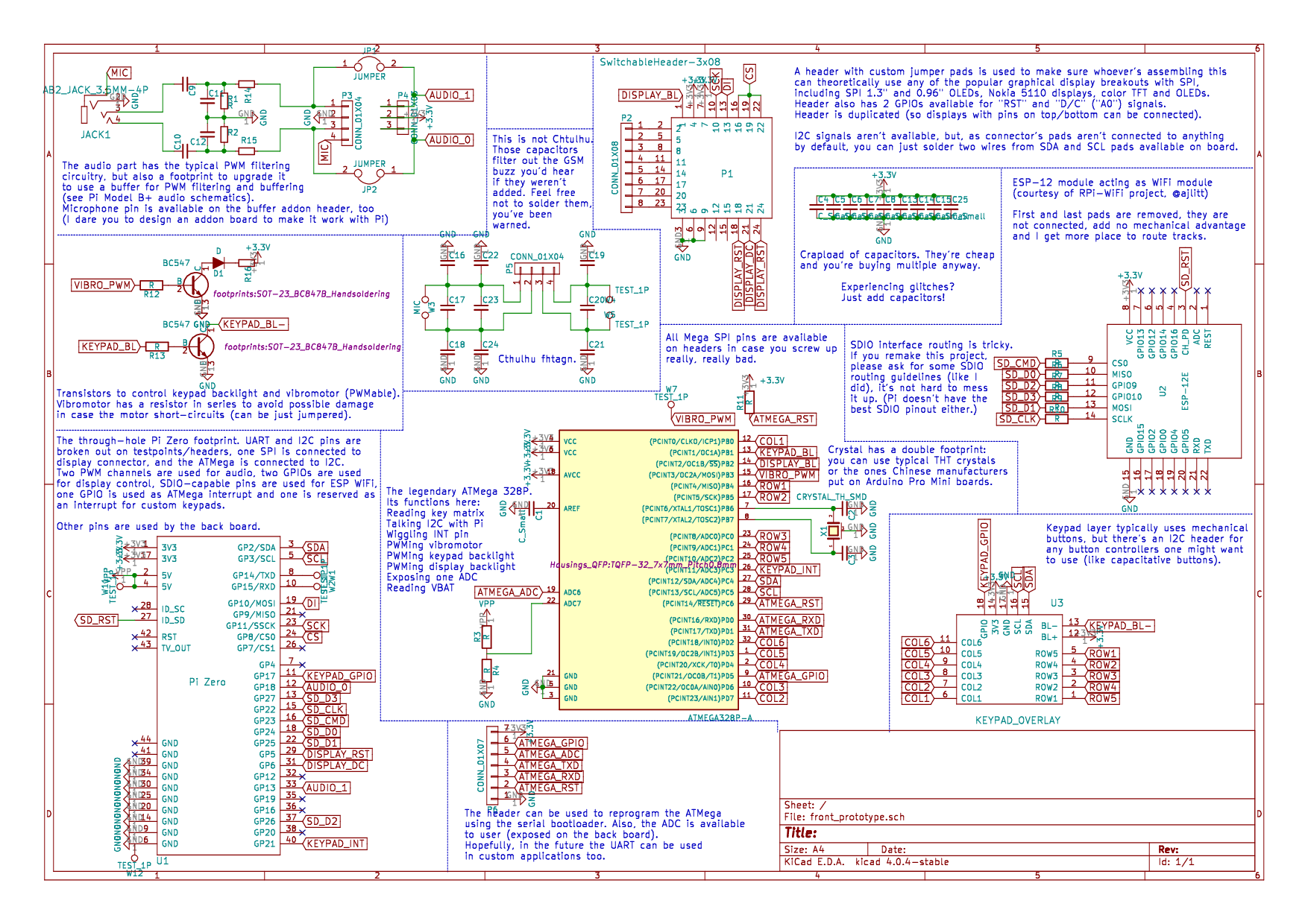
In the end, I got a nice laser-cut pogopin holder in shape of the boards, made as an acrylic-wood-acrylic sandwich (you can already tell I love things made from layers) and inserted all the pogopins (only those necessary for testing ATMegas/ESPs). Then:
- I soldered a spare Pi Zero to the Pi Zero socket pogopins - it was easy. Just align pogopins with the Zero socket and fill the Zero's holes with solder from the other side - solder will flow onto the pogopins, connecting them with the necessary pads.
- I soldered a spare ZeroPhone keypad I had to the keypad row/column pad pogopins, using a flat cable made from an old cable with connectors cut off
- I made sure that the board would not bend while only being held by screws in three points (and being pressed on by pogopins) - I had to add a makeshift clamp to prevent the board from bending.
- I added 4 wires for power/UART - UART being the most reasonable connection in this case, it allowed me to see the kernel debug output, access the console and easily solve problems if things went wrong.
![]()
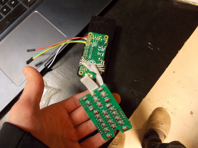
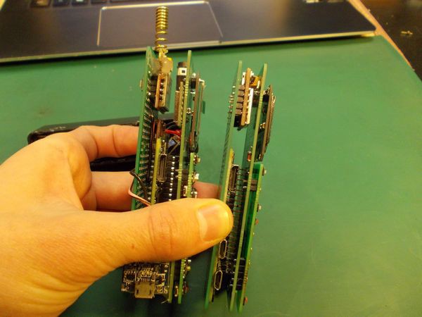
Keypad board, UART connection and the poor Pi Zero
Out of 5 boards I assembled, I had 4 with ATMega problems and had to replace those ATMegas - very lucky I tested them (the 5th one had loose wires I had to resolder). It was harder to test ESPs (they were working with interruptions, probably due to wire length), but it was quite simple - both ESPs I had initially just heated up, so the trash bin they went and I managed to find some working ones by calling a couple of friends. So far, it's been a good preparation to what I'll eventually need to do - test the ZeroPhones I'll make for sale!
![]()
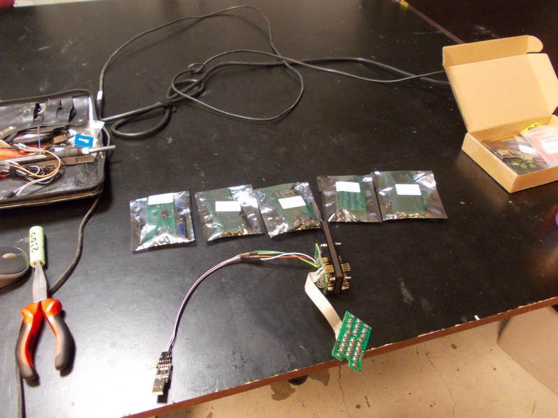
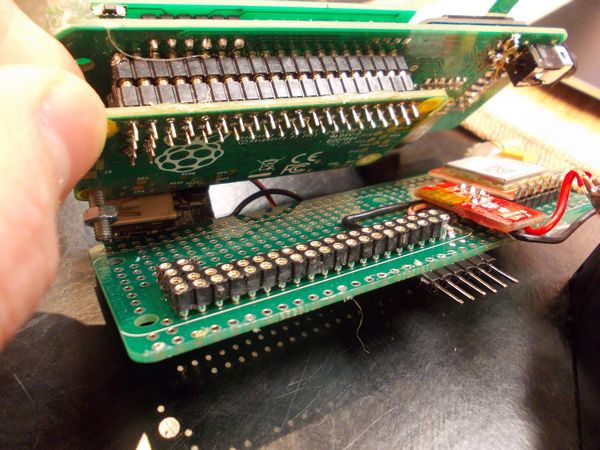
First batch of ZeroPhone alpha units - tested and going to contributors
I swear, one ESP-12 module I had just disappeared somewhere. ESP-12, if you happen to be reading this - I need you here. Come back ;'-(
-
Software: Tor control panel
02/08/2017 at 04:55 • 3 commentsTOR is a popular software that many people use for different purposes: anonymisation, .onion site access, changing IPs - anything goes. Today, I'm not going to show you anything that changes the world of privacy-related apps.
I'll just show a simple Tor control panel that works as a ZeroPhone app. You can just select "Tor control" in the apps and get a menu to turn Tor on or off, see your external IP and request a new one, as well as see some stats and check your connectivity. Here, you can read the app's code.
It's a simple but powerful demo of what ZeroPhone is capable of - something no usual phone can do. This app took 2 hours to write - including all the package installs, finding the right settings and Googling. Think about it - 2 hours of work for adding a Tor control panel to ZeroPhone UI.
Currently, the Tor daemon I'm running is just a proxy, not proxying anything unless you want it to. You connect the ZeroPhone to the local network, set up ZeroPhone as a SOCKS proxy for your browser - and browse Internet through Tor. The "be a wireless AP and serve all traffic through Tor" part is not implemented - I'll need to add a simple "Wireless AP" menu first, and that alone requires a day or two's worth of tinkering. After that, it's just iptables/torrc work to make it a secure transparent proxy.
I could publish my /etc/tor/torrc file, but I haven't checked it for security - I have taken most of it from the manuals/tutorials on the Web and I'm afraid people would rely on it. Instead, what I'll want to do is - during the v1.0 development, write a torrc file and have it checked by many people to see if there aren't any unsafe settings, then release it with the ZeroPhone. However, if there's as much as one person asking for it in the comments, I'll put it on GitHub and link here.
Oh, and by the way - if you understand Python, go read the code. Email/comment under this article if there's anything with the UI libraries I'm using, something bad about my Tor helper library I wrote, or, maybe, my coding style. I could use a code review, even though I had lots of practice. Also comment/email if you want some features added to the Tor app, or UI tweaked.
That's all for now on software - I'll go work on the next apps on the list!
-
Project state - back PCB finished; time for software!
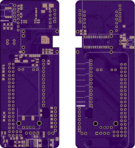
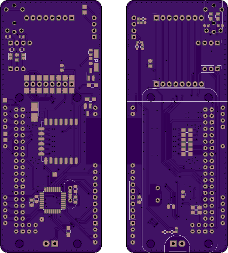
02/01/2017 at 04:44 • 2 commentsBack PCB finished! It's the least pretty PCB of all them. I was hurrying to send it off because I need to make the next prototype. The layout was also pretty constrained - Pi Zero, expansion headers, MCP23017 and GSM modem sitting flush from one side, TP4056, USB port, DC-DC and RTC from another. Routing could have been done prettier, but overall it's still good and I reached most of my goals. All the PCB files, including Gerbers, are on GitHub now.
![]()
Features planned but scrapped:
- General-purpose high-power LED (maybe better left as a mod? Will see when I'll be routing the board next time)
- Simple solution for hardware low-power shutdown - I need to consult some people about using TL431, I apparently didn't understand something about making a circuit that'd switch a MOSFET at 3V and have some hysteresis as well.
- Bringing out MCP23017 GPIOs taken by the RGB LED on testpoints - just not enough board space. There are two more GPIOs on the MCP that are free, I just forgot to bring them out - that's a task for the next revision (along with refactoring the routing)
Now, onto software goals. I aim to make the first revision of software limited, but polished. I think it makes sense to include the following features:
- Phone calls and SMS, rudimentary phonebook
- Simple number-keys-to-characters input (like on all mobile phones with a number keypad)
- A simple "nmap" app that scans the WiFi network the phone's connected to
- WiFi module power management
- RGB led control for notifications
- Twitter feed reader
- Music player
- Camera app
That should be enough for two weeks of challenges. Then, I should have enough requirements for the UI framework collected so that I know how the next version should look and can start planning the architecture for that.
Current roadmap adjustments:
3. Start developing v1.0 of software while Chinese festivities go on
    a) Coordinate the contributors, finally send out the alpha boards
    b) Once the festivities end, order a batch of boards and components
4. Once OSHPark boards arrive, test them, make a new PCB file release
    a) Find who's interested in reviewing kits
5. Once boards&components arrive, make kits and send them out
    a) Prepare the crowdfunding campaign
That's it for project state right now. Next week I can tell you any cool things I'll be able to achieve with the software - hopefully, I'll manage to make at least one of them this week!
-
Why do we need Open-Source phones?
01/28/2017 at 02:09 • 0 commentsMost modern smartphones have FM receivers. Obvious? Not if you're from USA, since phone resellers disable FM receivers in software to make you spend more money on data. Now that I have your attention, I want you to know you can take action against it, and I encourage you to.
This is an argument you can make in 10 seconds when somebody asks you about why you need an open-source phone. Just think how ubiquitous mobile phones have become in our life - and realize that the ones developing those phones are mostly big companies. Companies with their own interests, looking for new ways to get more money from you using the technology that's a requirement for everybody nowadays. Open-source technology has been solving problems like this for a very long time, so applying it to mobile phones seems like a logical solution. What can it solve for us, exactly?
Open-source is about getting the most of what you own.
For example, this phone has expansion headers with different GPIOs, which you can use to connect your own addons, to add whatever features you'd like to see in your phone. What would you like to add?
- An additional display?
- Extra buttons?
- Wireless radio to talk to IoT devices?
- FM transmitter?
- Ethernet port?
- NFC reader?
It's all possible, and is as simple as adding something to a Raspberry Pi - with all the tutorials and code already available for most occasions. To be honest, I just looked into my parts box and listed first 6 things that I spotted, and they all can be used with this phone.
Having an open-source phone removes many limitations that typical phones have. Whatever is not implemented, can be implemented - the code is available and open to modifications. If some hardware problems appear, it's actually possible to fix them yourself, not relying on somebody that has access to the code.
Generally, open-sourcing technologies gives companies less ways to hide things from us, and lets us do more with what we get. The possibilities we could only dream of might already be there, just not implemented, be it for lack of resources, interest, or just understanding that implementing a feature that less than a 1% of users would need wouldn't bring as much profit as developing a new, thinner and faster phone would.
Open-source is about not being left alone with your problems.
This phone has the phone functions working independently of the Linux OS it's running. As the Raspberry Pi hardware support is being better and better integrated into the kernel, OS support will stay with us for years. It'll receive all upgrades, especially the security-related ones. The phone and UI code are open-source as well, so fixing any future problems is possible without any support from the side and without depending on anybody.
With modern smartphones, having more complicated software and thus more possibilities for problems, manufacturer is ready to support a phone for a couple of years - a year in worst case. Manufacturers want to innovate since it's how they get revenue - there are people chasing new trends and they're the ones paying most money. Nowadays, our phones stop getting OS updates in a year or two - but the hardware is still not outdated and likely to be in good condition! People do assemble and release their custom firmwares for phones to make them do what they're technically capable of, but it's problematic to do because manufacturers don't release the necessary information. Thousands of man-hours are spent by enthusiasts porting new versions of Android to phones that are not really "old", just not supported by the manufacturer anymore.
And, if you think people aren't typically as motivated as companies, the wonderful thing is that there are lots of people that would solve their own problems, then share what they've made. Be it new programs, firmwares, hardware drivers or just simple usage tips, open-source is just a logical extension of what helped humanity survive and thrive - people helping other people.
Open-source is about learning.
The phone I'm working on is very simple. Each board's schematic takes no more than a single schematic list, and that's with annotations. The boards, while tightly packed, are two-layer and don't use any complicated techniques. The code is in Python, which is more than enough for a simple phone framework running on a Pi Zero, that's capable of multitasking, has various UI elements and APIs for developers - all that while still being easy to read, as well as learn from.
You could sit down, read the worklogs, look at the schematic, the boards, the code - and learn plenty about how this phone works, how phones work in general, about the design decisions made to achieve the project's goals and problems that were encountered on the way.
In contrast, modern phones are complicated. You won't find schematics for a typical phone, and code is complex because it has to be. Modern phones have to deal with every function that users want, every API developers want to be available, every case that can appear and every legacy function that has to remain in the code because software that was written at some point depends on it.
Open-source is about protecting our data, identities, things we own and care about.
In 2014, we saw evidence that various big companies were forced to leak our data to the USA government. Most of them complied and lowered security of their programs, computers, phones and services they offer, or left weaknesses government intelligence agencies could exploit. There are at least three problems with this I can spot instantly - first and foremost, constitutional rights to privacy of people all over the world who were affected by this. Moreover, if a government intelligence agency can do it, so can a sufficiently determined hacker, and at this point it's a safety issue. Furthermore, there's less and less people trusting the USA government nowadays - and I know most of them would be happy to be wrong in their lack of trust.
Not only that, 2010s are the years we started raising awareness about data people themselves leak to various companies. People started to feel the influence of targeted advertisements - from funny and inappropriate, to annoying and outright dangerous.
Open-source software and hardware, traditionally, has been less endangered by this. It's much harder to insert a backdoor, the code is open so that people can independently review its security, and privacy-endangering features are easier to remove.
Next week will be software writing week - as soon as I finish testing the protoypes I'll be sending out and send the back board to OSHPark. I hope to write less about the obvious things and more about what this specific phone can achieve with the right software ;-) As usual, every point made is open for discussion - I'd love to hear your opinions!
-
Hardware: making the phone accessible and using Chinese breakouts
01/26/2017 at 21:56 • 5 commentsThe phone has to be accessible, and by that I mean that the components should be easily sourceable. What are the criteria for this?
Less obscure components. If there's somebody not able to get the DC-DC chip or specific inductor I'm using (say, shipping is more than the IC costs), I will try to do at least one of those things:
- make it optional to use (like I'm doing with the audio buffering on the new board)
- make footprints compatible with other more popular ICs/breakouts
- make it work some other way
Boards should be easy to make. That means two-layer boards, using PCB design settings that are easy for board houses to make and using dimensions that are typical limits of board houses (also, encouraging pamelizing boards). While I'm not aiming to make the boards etchable at home (this task is high effort/small advantage for the project), I encourage anybody who needs this feature to try and make the boards suitable.
Components should be easy to solder. No BGA, LGA or anything that needs a heat gun. Unless absolutely necessary, I'll avoid this like a plague. BGA and LGA are very nice technologies, but I'll leave them to people capable of actually soldering them right and having the right tools - and that's a pretty small number of people, if we look at who this phone is aimed for. Also, breakouts. If a screen has (x < 0.8mm) FPC pitch, needs 10 or more passives to operate, as well as a boost converter - I'll just pick the one with a breakout that has 8 pins, with everything already soldered and, hopefully, tested.
Let's see some examples.
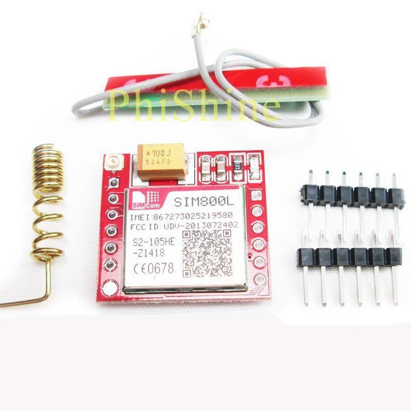
The GSM module
SIM800L has this nice red breakout made by Chinese. It's small, yet exposes the most basic functions necessary. Also, it's 6$. For example, #DIY GSM arduino FR4 cell phone uses it.
![]()
For 6$ you get this small breakout board with 2.54 headers, a big SMD capacitor that you'd definitely need, two antennas, all the passives, NET led and easy-to-use SIM socket. That's economy of scale in action - just imagine how much it actually costs at TaoBao!
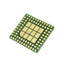
Of course, you can get the bare module for 4$ from the same eBay, it'll be LGA (same as on the breakout). What's LGA like?
Good luck doing that without solder paste and at least a heat gun. By not using the breakout, I make the project much more expensive and much easier to assemble without special equipment.![]()
But, of course, that's simple stuff and nobody would argue with that. A better example?
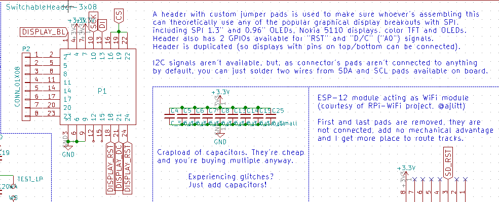
Display breakouts
So, theoretically I could limit the phone to one screen. That's a good decision, and that's the one I'm going to take now in terms of hardware support. What's about hardware? There are multiple breakouts on eBay. Here are pinouts of the cheapest breakouts.
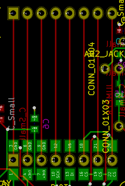
Type Pin 1 Pin 2 Pin 3 Pin 4 Pin 5 Pin 6 Pin 7 Pin 8 TFT 1.44/1.8 GND BL VCC SCK MOSI DC CS RST Nokia 5110 GND BL VCC SCK MOSI DC CS RST Color SSD1331 OLED GND VCC SCK MOSI RST DC CS 1.3 SH1106 OLED VCC GND SCK MOSI CS DC You get the idea? I've made a custom header footprint that allows different breakouts. How it looks like on schematic and on the board?
![]()
![]()
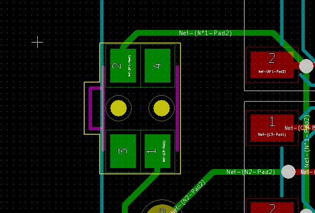
How does the alpha board's display header look when a SH1106 OLED is soldered on?
![]()
In the end, I have a simple way to support multiple displays - leveraging Chinese breakouts, the fact that most displays use SPI and some solder jumper magic.
WiFi module
While it's entirely possible to route a ESP8266/8285 chip on my board, as well as add an antenna, it's much, much easier to just add a ESP-12 module, as an ESP8266 chip would likely need to be reflowed, use lots of passives and wouldn't even be cheaper for the end user to get - again, economy of scale. The ESP-12 is kinda bulky - as @Tisham Dhar suggest, it's possible to use a small ESP8285 breakout and save some space. However, the ESP-12 modules are manufactured in such large quantities that they're getting cheaper and cheaper to source - and even being resold by local distributors in some smaller countries.
Audio output
I went the proven way - using PWM to get audio output, just like Raspberry Pi versions do. There are two ways to achieve this - old and noisy, and new and less noisy. Let's compare the schematics.
Old way:
![]()
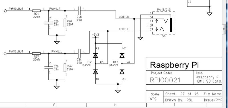
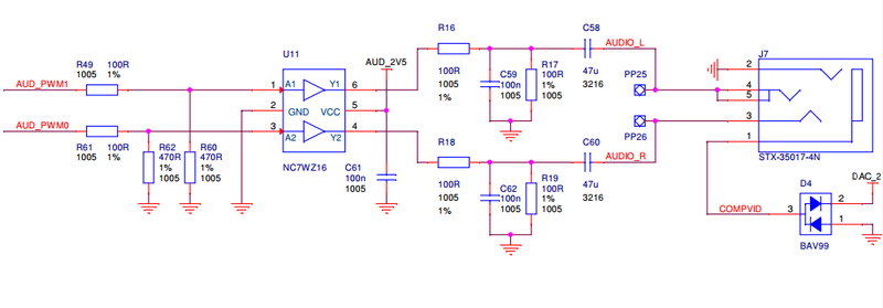
New way:
![]()
images from adafruit.com
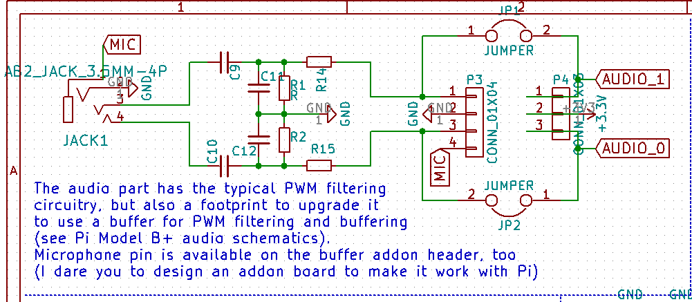
See the common part? The "two resistors and two capacitors" part. The new schematic just has a buffer, a voltage divider before that and separate power supply, the other part's the same. However, the buffer IC and small 2.5V voltage regulator might be hard to source for some - while some will absolutely need to get rid of constant quiet noise. What's the solution?
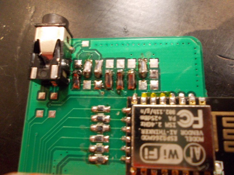
![]()
How the board looks:
![]()
The pin headers make it possible to add a small "audio buffer" addon-board in the future, while being easily jumperable if you don't want the buffer to be there. I think I should probably add the ESD diode footprint as well. It's quite optional, but this is an outside-facing interface after all and problems might appear, so it'd be nice to give a possibility to add the interface.
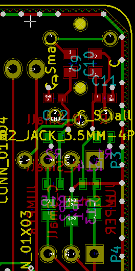
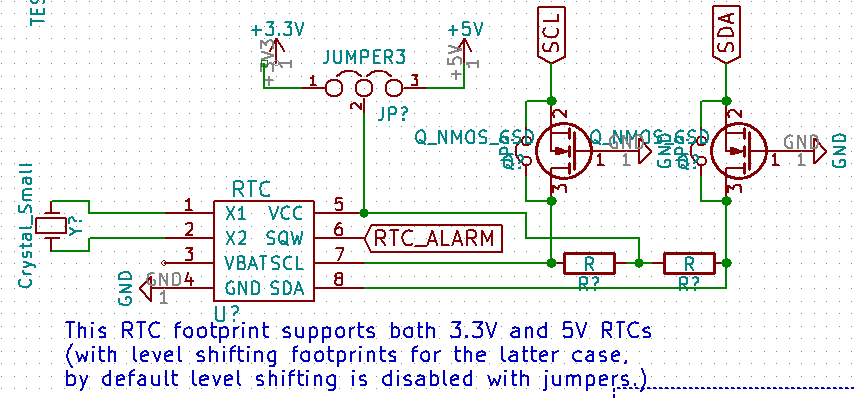
Real-time clock IC
Those ICs typically use SO8 footprint and the same pinout. The only problem that might appear if somebody wants to go "full cheap" and use some DS1307 chips, which use 5V. Possible solution for this:
![]()
I might end up scrapping this if it proves to be unpopular, but for now, the board space taken by this will likely be very, very small.
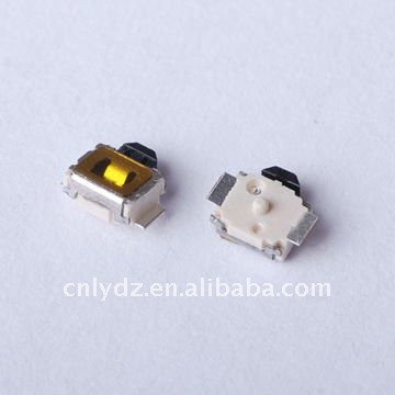
Keypad side switches
I was searching for SMD side switches on eBay, to make some buttons on the side of the phone - you know, camera, volume buttons and such. I found two most popular types - with 4 and 2 pins, no other differences. Say, a typical button connects pin X to pin Y upon keypress. Those with 2 pins have pin X on one side and pin Y on the other side. Those with 4 pins have one pin X and one pin Y on each side. Let's show you what I'm talking about.
![]()
2-pin button
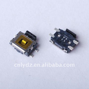
![]()
4-pin button
The only difference is that buttons I've got are different from those pictured - both have 2 plastic pins on the bottom, so that part was similar in my case. I want users to be able to use both 2-pin and 4-pin buttons. My solution?
![]()
Two of four pins are NC so pins never short-circuit, no matter which buttons you're using.
This is not the end of making footprint choices and searching for suitable parts. I still need to sort out DC-DCs, USB connectors issues (usual USB full-size female connectors are huge), Li-ion charging and some more issues. I do hope I've given enough insight into how I'm making phone as accessible as it is when it comes to sourcing components.
-
Project state - Beta hardware almost finished
01/26/2017 at 02:33 • 1 comment![]()
New revision of front PCB was developed. It's hopefully final for now (Murphy's laws still apply). I've changed a lot of things, such as component placement, ATMega pin usage and audio connections. with a PCB like this, it's "solder components and it works", just like it's supposed to be. This Monday, front PCB was just sent to OSHPark (and I want to express my gratitude to @oshpark for giving us a discount, the project can now move forward much faster!). Also, props to @jaromir.sukuba for reviewing the boards and suggesting many useful changes!
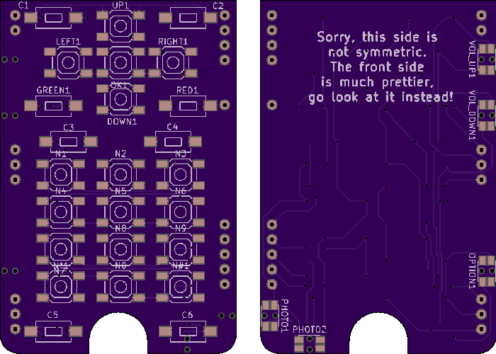
![]()
The keypad PCB got new features! First of all, I erased all traces and let my OCD take over. As a result, the front side has fully symmetrical traces (once you solder the keys on, the board is supposed to be beautiful). @Lars R. suggested capacitative buttons. I'm not going to make that myself (I like mechanical switches), but I made sure that whoever wants them can add them - keypad now has I2C lines coming from the Pi (as well as power and one GPIO for interrupts). Now anybody can just design another keypad PCB with a capacitative button controller. Keys were moved and made easier to solder, too. Also, there are two side button options on eBay - I made sure keypad PCB supports both.
![]()
The back PCB is not as simple - it's still work in progress. I forgot that it needs all the power management stuff, like RTC with battery, 5V generation for USB (still using available components), a full-sized USB socket (placed in a non-weird way) and have access to Pi USB lines. Hey, let's talk about the back board!
---------- more ----------
Back board:
DONEs:
- I decided to bring out all available GPIOs to expansion headers on sides of the phone, to female headers. They're grouped and positioned based on how they're commonly used, the most logical way I've found. I even have included the TV out signal on one of the headers, hope somebody can make use of that.
- I had to add a MCP23017 GPIO expander. The phone's out of GPIOs with all the interfaces taken, and I needed some management functions. Good news - it should be supported by Linux drivers, so it actually creates Linux native GPIOs and we don't need another daemon running exclusively to work with this I2C device.
- I added an RGB notification LED - a feature I missed so much from Nokia times, something that modern phones have scrapped (for what, 0.02$ in BOM?). It's kinda bulky at the moment, supporting THT RGB LEDs, but I plan to add an SMD footprint in parallel.
- I also added a single large LED (again, idea courtesy of @Lars R.)! Could be used for camera, notifications, as a flashlight or whatever else you can imagine - maybe IR backlight for night vision.
- I understood there better be an RTC - with all the features a phone like this should have, proper timekeeping is something absolutely necessary. The footprint I've added is quite generic - many RTCs will fit. As a last resort feature, there's a possibility to use older 5V RTCs - there's even level shifting components added (jumpered until somebody really needs them). Unfortunately, the SIM800 RTC battery pin is not available on the breakout used =(
TODOs:
- Making the footprints for GSM modem breakout, DC-DC breakouts found on eBay and TP4056 breakouts
- Choosing a RTC battery (and a holder)
- Figuring out the component positioning - I've already planned out the expansion header positions. Battery connector, USB socket, battery itself? Not so much, all limitations apply. Add the modem, RTC, DC-DC and expansion header labels, and it quickly starts to get tricky - not to mention the modem for 3G/4G is likely to be much bigger (and take USB?)
All of that till Monday - I want to speed up the prototyping stage, that means I have to send off the back PCB to OSHpark on Monday.
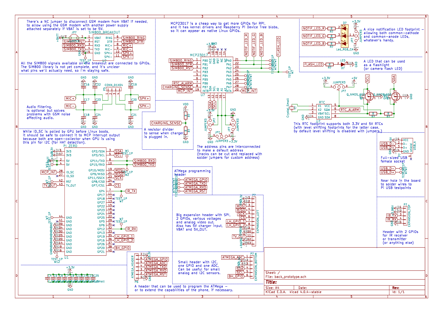
I think I'm done with articles for today - I liked the way I annotated back PCB schematic while drawing it, I think I should go do the same with the front PCB!
EDIT: Done!
![]()
-
Hardware: PCB dimensions and sandwiching
01/18/2017 at 17:11 • 5 commentsThe phone has to have plenty of hardware both on front and back, as well as some on the sides. Usually, the keypad phone designers built a phone with one big mainboard (as big as the phone itself) often a separate flex PCBs for keypad/side keys (occasionaly using mechanical side keys). In flip phones, there'd be another PCB for the LCD panel most of the time.
How do I know? I spent 4 years fixing mobile phones (also PCs and laptops) for a living, and I used to repair my own phones before that. I didn't exactly design those, and the repairs would be "replace that module" most of the time, but it gave me insights into what components they typically use and how they're put together.
Dimensions
Two months ago I started making mockups out of paper so that I'd have some insight into what the boards should look like. It was clear there'd have to be at least 2 PCBs - one for the front and another one for the back. I wouldn't be able to make the thing smaller than the Pi Zero,and making it slightly wider wouldn't be such a big of a problem. Pi Zero is 31mm wide, I just rounded it up and got 40, which looked perfectly fine.
I was going to order the PCBs from DirtyPCBs, and as I couldn't realistically aim for 5x5cm panel, I chose 10x10cm. Then I measured the keypad layout I was aiming for, the display height and understood that it'd be close to 10cm height, so I might as well make it 10.
Keypad
Now, when I was sure the thing would need to be a PCB sandwich, and I knew the dimensions. I made a list of features for the front panel. After much planning, I had to add a MCU for the keypad, which adds a step to the assembly. then, I understood that routing the keypad traces on the same PCB as the MCU, ESP-12 and Pi Zero headers wouldn't be as comfortable to do as it looked like, so I opted to make the keypad a separate layer. Is it still possible to route it on the same PCB? Yes. Would it be possible to make it as quickly as I did? Doubt it.
However, if there'll be a significant demand in making the phone thinner, it should be possible to route it all on one PCB. Not only thickness comes into play - the front and back PCBs will be able to fit on one 10x10 panel, which is a 50% off PCB manufacturing costs if you're assembling it yourself!
![]()
Inter-PCB connections
It turns out 2.54 headers are a cheap and solderable solution that works well. You can use a single 2x20 header to connect all three boards, a couple of headers to atach keypad PCB to the front PCB and some more headers for the GSM module. When I was designing a board, I knew I'd need to make a KiCad Pi Zero part. I added 2x20 2.54-spaced plated-through header, but didn't pay attention to the fact that the plated-holes wouldn't have enough width for a typical 2.54 header. When I got the boards, I was initially disappointed but then understood it's actually possible to make it all fit - just press the connectors in a little. Moreover, the boards are held together without soldering them (with the exception of Pi Zero itself) - it doesn't mean it makes a secure connection electrically, but it makes it all easier to be soldered together.
Furthermore, using 2.54 headers means that I can use machined headers to make a phone that's thicker, but can be easily assembled and disassembled. I assembled a prototype that way, and it works quite well, though I need to use hot glue to hold the back PCB and Pi Zero together. Also, when using machined headers, I need to add a screw with 3 to hold the boards together because otherwise pressing on the keyboard makes the whole setup bend enough to disconnect the machined headers (it's better on a prototype with soldered headers).
The downside of using simple pin headers is that, in order for the phone to be disassembled, you have to desolder 40 (best case - 25) 2.54 header pins from both sides. That's very uncomfortable to do, and I'm ashamed to state I don't yet have a solution for easy disassembly. I hope I'll find a way to still allow easy disassembly, or at least work around this as efficiently as possible.
![]()
When I look at the prototype I'm using now, it consists of 9 (nine PCBs):
- The Pi Zero in the middle
- The front PCB
- The display breakout PCB (soldered to front PCB)
- The keypad PCB with all the keys
- The ESP-12 module (which is just a black PCB with ESP8266 chip, SPI flash and antenna on it, covered with a shield)
- The Li-Ion charger PCB (harvested from a powerbank, using some SOT 5-pin IC for charging) (won't be in final version)
- The back PCB
- The Li-Ion fuel gauge PCB (for logging the battery life of this prototype, uses MAX17043) (won't be in final version)
- The SIM800 breakout PCB
While that count can be decreased (I'm not smart enough to predict the mechanical stability of this), it makes for easy assembly and easy sourcing of the parts. Moreover, using off-the-shelf display breakouts means you'l be able to use another display if necessary - but that's a topic one of the next hardware/design decision writeups!
-
Project roadmap, alpha boards published (DO NOT ORDER)
01/17/2017 at 21:09 • 0 commentsSo, I've been learning KiCad as I've been making these boards - literally my first board in KiCad, coming from Eagle CAD. Furthermore, there were component sourcing problems, unknown variables, untested footprints, too many questions and no answers. Thus, the boards published have bugs, mishaps and poor design choices. The boards are for reference only, as well as for those who want to get familiar with the project's design choices, and for at least a little bit decreasing the "bus factor" variables.
Here they are. Here's the TODO on those just so you know how much is to be fixed/improved. DO NOT ORDER these boards if you'll be saying I didn't warn you afterwards. It was necessary to order them because there are people interested in contributing and I hate to delay other people, especially when they want to help with my project.
Roadmap
The current roadmap as I imagine it is:
- Check the current version (actually, all that's left to check is the vibromotor circuit)
- Fix the front&keypad PCBs and send them to fab
- (*In parallel) assemble and send out alpha prototypes to testers/contributors
- Make the back PCB and send it to fab
- Start developing v1.0 of software to accompany boards that'll arrive
- Coordinate the contributors
- Once the boards arrive, assemble a prototype for testing
- Possibly, wait for some components from eBay/wherever stuff has to be ordered from
- Send out boards to people/maker outlets for reviews
- Publish board files
- While the shipping goes, make assembly instructions and publish them
(* Things in lower-level lists are done more or less in parallel with the high-level task)
That's what I need to get the first revision ready and start building the community of users. Is that enough to start the ball rolling? Of course not, there'll be lots of additions, changes of plans and sudden discoveries - and a lot of reading about similar projects, ways they solved problems, tradeoffs and any tricks that could be handy. Moreover, I'll re-read the roadmap over this week to see if I've missed anything - and update it here.
That's all for today. For this week, I will also do a writeup on a part of this project - for now, on hardware design decisions.
-
Project description and Frequently Asked Questions
01/14/2017 at 03:34 • 39 commentsSubscribe to hear project updates and be notified when crowdfunding goes live!
![]()
What is this?
This is a smartphone, with a Raspberry Pi Zero at its heart. It's open-source*, Linux-powered and you can make one yourself for 50$!
*except some parts, replacing which would make it crazy expensive
Why?
Because it has so many uses, the idea sems to be obvious and yet there isn't a project like that. Moreover, I've been studying the topic for a couple of years now and this project is meant to be useful to other people as well - so I have a chance of commercializing it (while still keeping it open-source).
What can it be used for?
- Calling and SMS - this is the first functionality to be implemented, and will be considered crucial in the development.
- All the basic apps - alarm clock, calendar, calculator, phonebook, file browser, web browser and music player.
- Your own apps - SDK will be provided and it will be developer-friendly. The laand I'll personally expect, if not at least aid with, social media apps - for a good start, since those are the apps people spend most time in.
- Running Linux software - since it's a computer after all, you can run ARM compatible (thus, almost all) Linux programs on it. A Raspberry Pi can give you a desktop with a monitor, keyboard and a mouse? This phone can, too! You like to use SSH, like me? It's going to be available!
- Pentesting - lots of fun, a nice hobby for many and well-paying work for some, this phone can do it too.
- Security and privacy - one of the features that isn't typically provided but can mean anything from something simply bringing peace of mind to a matter of life and death.
- Experimenting - there'll be a sensor port available for connecting anything you think could add useful functions to your phone. Want to wake up when the sun rises? Add a light sensor! An additional display for notifications? Easy, connect and write code! A Geiger counter? Can have it, too!
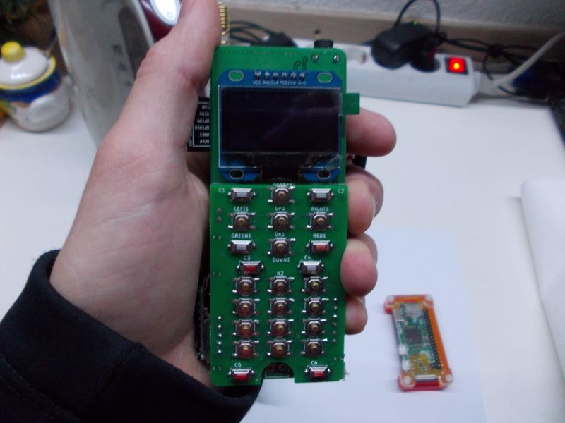
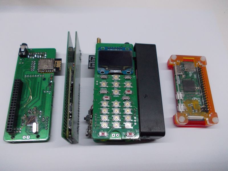
![]()
- Front panel (used as a Pi Zero shield giving it WiFi and screen&buttons for using pyLCI)
- A prototype I'm using to see how thin it can be made
- The current prototype I'm using for development, with a powerbank hotglued on the side for portability
- Pi Zero for scale
But why X/Y/Z choice was made?
There are so many questions about project choices that I have a separate page for them and will be happy to add answers as your questions come in!
What OS is used?
It uses Raspbian Linux, which is currently based on Debian Jessie. This is because it can be tailored to suit our purpose very easily, and will still be /upgradable in the future - this project doesn't need a separate distribution since that's prone to obsolescence and is a maintenance nightmare (but I do plan on providing ready-to-go SD card images if the demand is there).
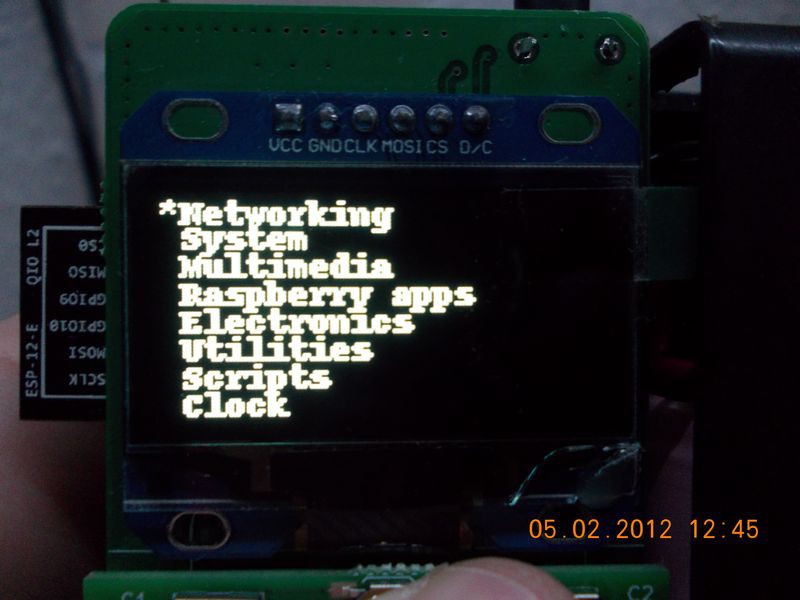
As for the user interface (controlling screen and buttons) - it's written in Python. I'll be using pyLCI as a base, but it's clear for me it needs a rewrite to have all the capabilities a decent mobile phone UI should, and developing a good UI is one of the main goals of this project.
![]()
pyLCI used for a management/configuration interface while the software is still being developed
How smart is it planned to be?
As it's Linux-based and can support all the programming languages typically used with Linux, I expect many original ideas for apps from all kinds of people. I myself will be working on a set of apps for productivity and healthcare - making it a great helper in everyday tasks and goals, instead of a distraction that we typically perceive smartphones as.
What are the privacy/security features you're talking about?
It's Linux, and the apps running on it are open-source (therefore more likely to be secure and not privacy-invading). If you don't like a feature because it's a privacy/security concern, you can just disable it. If an app you're using has any unwanted code, you can just remove it. It doesn't depend on any butt^W cloud services - not if you don't want it to be. Since, again, it's Linux, it's got many security-related software available, and you can install it - be it a firewall, I2P/Tor node or a secure messenger of your choice.
As a bonus, the software is meant to allow you to fully utilise all the features the hardware supports - including some manufacturers don't usually include in software but surprisingly helpful. For example, you can use modem-specific commands - that allow you to detect GSM jamming, fake GSM base stations and intentionally weakened GSM encryption (I know SIM800 has the first and provides data to help with the second, for a start).
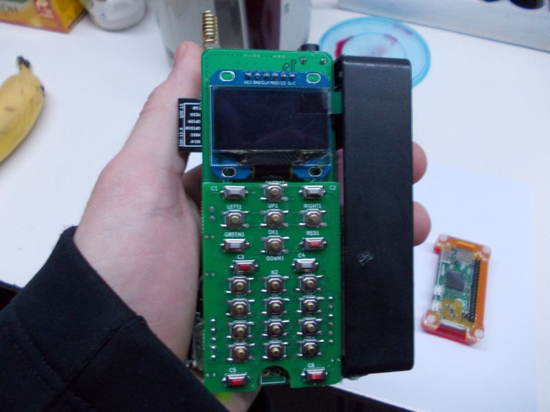
![]()
Together with the powerbank I'm using till I can get a pouch battery that's large enough
How is it different from all those open-source phones available?
It's the only phone you can assemble by getting all the parts yourself (for less than 50$), not using any rare parts (everything's available on eBay) or fine-pitch soldering (typical pin spacing is good old 2.54) You can even breadboard this phone if you're dedicated enough. This is possible because of all those cheap and great Chinese modules, wonders of mass-production economy and smart design choices while picking components.
More importantly, this phone won't be left with outdated OS if the phone's development will stop. Since it runs stock Raspbian (with mods), it can also be updated the same way you'd update your Raspberry Pi, and you can easily do it yourself. That means you won't be left with unsecure versions of software that'd make your phone insecure or buggy - which is a feature almost none of phones listed currently have, and I'm not even talking about Android phones.
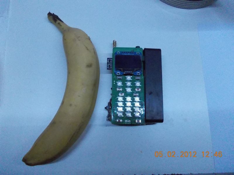
![]()
Again, for scale
How come all the parts are easily available and are so cheap?
Let's see.
- Pi Zero - easy to get despite people on Internet still telling otherwise (I got 5 by now). Let's say it's 5$ and 5$ for shipping.
- SIM800 modules - available in large quantities from eBay, 5$.
- ESP8266-12E used for WiFi (as per RPi-WiFi project) - 2$ from eBay
- Two-layer PCBs (two 4x10cm boards, one 4x6cm board) - can be ordered from your favourite fab or whatever people on Internet give good reviews about.
- ATMega328P - can be desoldered from an Arduino Pro Mini that's typically 2$ on eBay, and it comes with a bootloader already! If you don't have a heat gun, you can just buy a bare chip and burn a bootloader to it using a programmer.
- LCD screen - 5$ on eBay. Besides, a project like this can use other screen breakouts with similar characteristics (such as the ubiquitous Nokia displays) - it's just a matter of writing a driver, which is easier than it sounds, and the front board accepts different display pinouts.
- Battery - you can use cell phone batteries, pouch and 18650 cells.
- TP4056 battery charger - modules are available from eBay, 1$.
- Buttons for keypad - 2$ from eBay (there are 3 types used, but you can omit one).
- 2.54 headers (both dual-row and single-row) - dirt cheap. Won't be more than 0.50$ to have enough to assemble the phone.
That's 27$, not including the battery and PCB. PCBs are cheap from usual 10PCB places (like DirtyPCBs) if you do group buys, alternatively, there's @oshpark and similar board houses that have good prices. Batteries can be taken from mobile phones, or you can get a battery for one of popular Samsung phones and use it, for example. In total, it should be 50$ or slightly more.
Also, price falls quickly if you're assembling one or two more phones for your friend, too - eBay sellers can make discounts when you buy more than XX$ or "make an offer", and PCBs are cheaper (you won't get less than 3 pcs of PCBs in any of usual board houses, so you have to pay extra even if you need only one board - you'll still get two more)
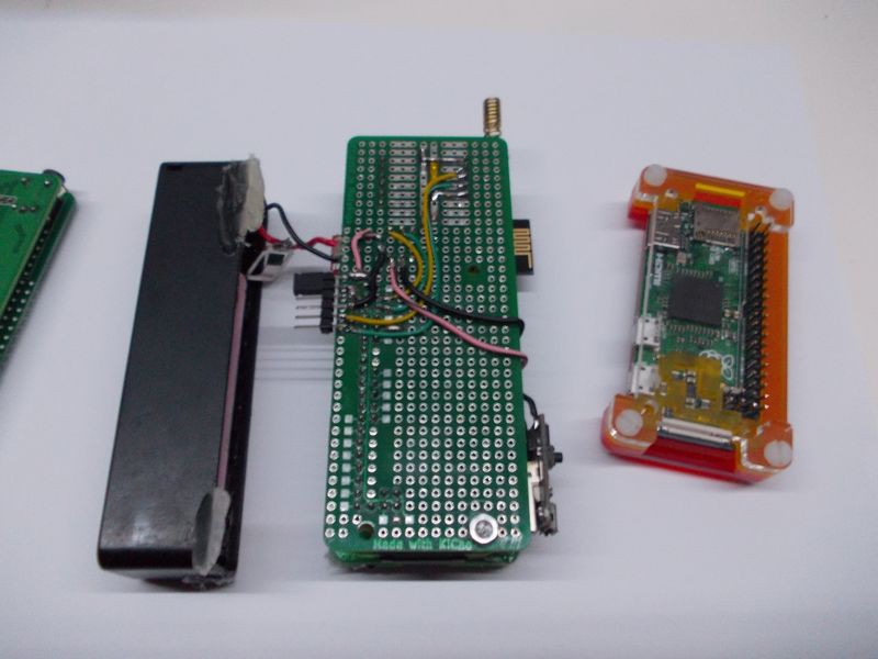
![]()
Currently the back PCB with GSM modem etc. is just a custom-made protoboard, which is exactly what you want when you're not yet sure what are the coomponent placement and connections necessary
How do I assemble it?
You'll need a soldering iron, with a fine tip and enough power to heat up ground pins, which is an issue for Pi Zero (25-30W should be sufficient). You'll also need clippers to clip 2.54 headers to make them shorter - they are used for board interconnects, and in some places they're a little too long for that. Lead solder and a soldering station will make assembly much easier.
A heat gun will help - in the current revision, there's an ATMega328P on the board that's used for keypad reading. It's convenient to solder chips like this using a heat gun, and if you're getting it from an Arduino Pro Mini, you'll definitely need it.
-
Vision behind this project and thoughts about OSHW phones
01/14/2017 at 01:14 • 0 commentsI myself believe that we need to get to a fully open-hardware phone that will be as accessible as this one. However, temporarily using some pieces of closed-source hardware is the only way I see for this project to gain enough traction to actually mean something in this world of big corporations with enormous resources. Open-source matters to me a lot, and I believe that once this project is complete, it will be a stepping stone to exclusively open-hardware phones. Why do I think so? And why am I disregarding the fact that parts of hardware aren't fully open-source - especially the GSM modem?
Considering the current state of open-source microcontrollers, SoCs and RF basebands, focusing on open GSM modems is not the part where this project could really help the open-source phone movement take off on a large scale. The part that's actually lacking is a user interface and an universal hardware platform - that you can use with any hardware you see fit, both fully open-sourced chips and those with no public specifications/using closed-source firmware blobs or microcode. This is also the part that helps build an ecosystem, the interface is one of first things these days that people look for. You generally got to believe in the platform, to see something in the platform to make yourself write an app for it. People that'll impulse-write an app, while playing with the framework, will come and go, will they maintain it? Will they write another one? The framework would need to be really cool for that.
But what can we do to get back the progress open-source is missing? Technology runs forward. Phones, and the technology in general, become more and more complicated compared to what we make at home. Hobbyists often get outdated technologies to play with, which is because the price needs to be low enough and there should be first adopters to help make those technologies more accessible for hacking upon. Often the path is like this - modules get replaced by superior modules, fall in price because the high-quantity demand is lower, manufacturers sell their surplus at a lower price to distributors and, if the documentation exists, the tech can be picked up by companies like Adafruit, Sparkfun and other resellers. Bits of code get written, are assembled into libraries, accompanied by breakout boards, code examples and wiring diagrams. This takes time and is one of many reasons tech is outdated when we get to it, compared to the sweet stuff you can get if you're a company with a popular product bringing revenue to you - and potentially to everyone who gives you a good enough offer to become one of your suppliers.
Again, that's just one of the reasons we often get outdated tech to play with. What do we do? We 1) indicate that the demand is there 2) work with manufacturers that can cooperate with hobbyists. So far, there are companies who, if even can't provide fully open-source hardware, do their best to help is in our interests. However, that gesture of good will usually does not last if we don't bring them profit - which is understandable, considering that companies need to keep afloat and bring profit to develop new technologies to keep their competitive edge.
That, of course, means there should be a community behind open-source phones. Just like there's a community of programmers behind JS frameworks nowadays, what could theoretically stop us from making it as far as GitHub's load balancers can handle? I want your comments about this - I'm kinda in the dark here.
Tinfoil hat on. What happens if we don't keep up? It's possible we'll have the same technology gap we now have with GSM modems. Nobody was motivated to keep up with the rapidly developing technology, and now every phone carries a black box that's incomprehensible. Not only it hinders innovation, what if a covertly rogue-ish government (think Congress-approved NSA programs) decides the black box is a good enough place to tap into whatever's flowing through and labels it as "fighting terrorism"? We're at the mercy of manufacturers, governments and law enforcement on this one, and they're all controlled by the same imperfect humans inhabiting our world.
We've come a long way, and as we progressed we installed more and more social and technological safeguards to prevent other people with bad intentions from doing bad things (and to keep honest people honest). One day, it could happen that this will become one more front where we'll become vulnerable without expecting the huge scale of vulnerability. In the world where large volumes of information help people manipulate other people's opinions - what happens if somebody malicious gets just enough data to get insights about making people support whatever his goal is?
Tinfoil hat off. It's just a shame that sometimes people wearing tinfoil hats sometimes are the ones to guess what'll happen. There's always another way to screw things up when it comes to humans governing humans, and I feel like there's a hole in our pocket that our mobile devices with all their sharp edges help create.
The most important thing, however, is that a platform like the one I hope to bring you can show the most important benefits of open-source phones. With an OSHW GSM modem, the benefits are much less tangible, more, let's say, spiritual and less noticeable in normal operating conditions. With an OSHW mobile phone platform come the benefits of hackability, repairability and improved security, which are much more popular as problems regarding these occur much more often. Open-source hardware, historically, has fared much better than the closed-source alternatives when it comes to these three problems, and it can help acquire a much larger initial user base.
There's a lot to add about the important things. Hardware is useless without software, software is useless if it won't accomodate future changes (and changes from whoever needs something slightly different), and that I'll periodically ramble about, hoping that I can spark a discussion to get some new ideas and get rid of those not applicable to the real world. Whatever you like/don't like/want to discuss, comment here, write me to crimier at yandex dot ru or maybe post to /r/tin_foil_hats, but I'd like to hear your thoughts. Oh, and I there are writeups about actual hardware too!
ZeroPhone - a Raspberry Pi smartphone
Pi Zero-based open-source mobile phone (that you can assemble for 50$ in parts)