 lion mclionhead
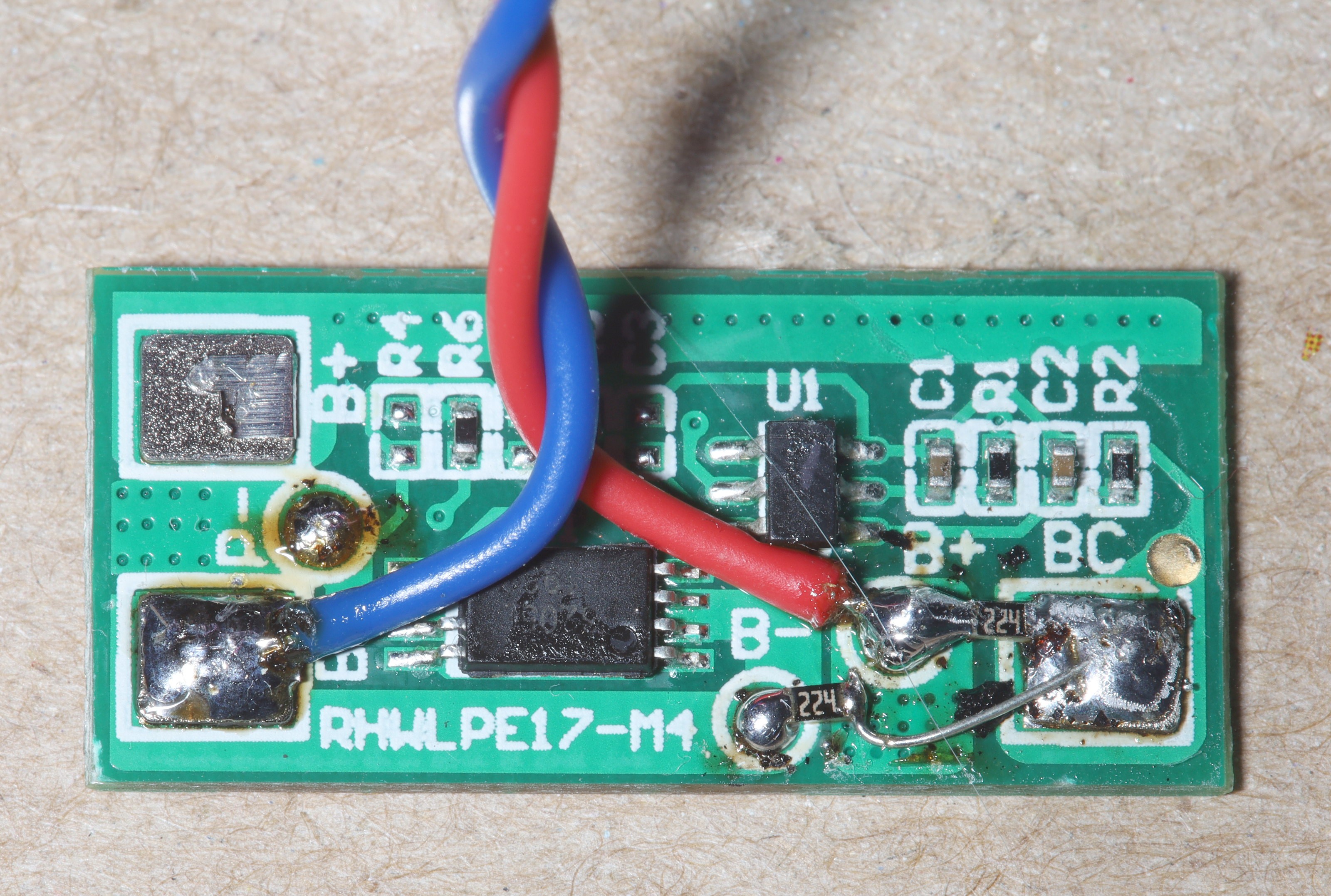
The previous wiring diagram failed. In fact, it was necessary to connect GND to B-, 8.4V to B+, & simulate the center tap with a pair of 220k's. The camera DRM requires the center pins to respond to a challenge which requires the battery brain to be fully functional.
The other requirement with this is the battery must be powered up before being inserted into the camera or it'll never power up.
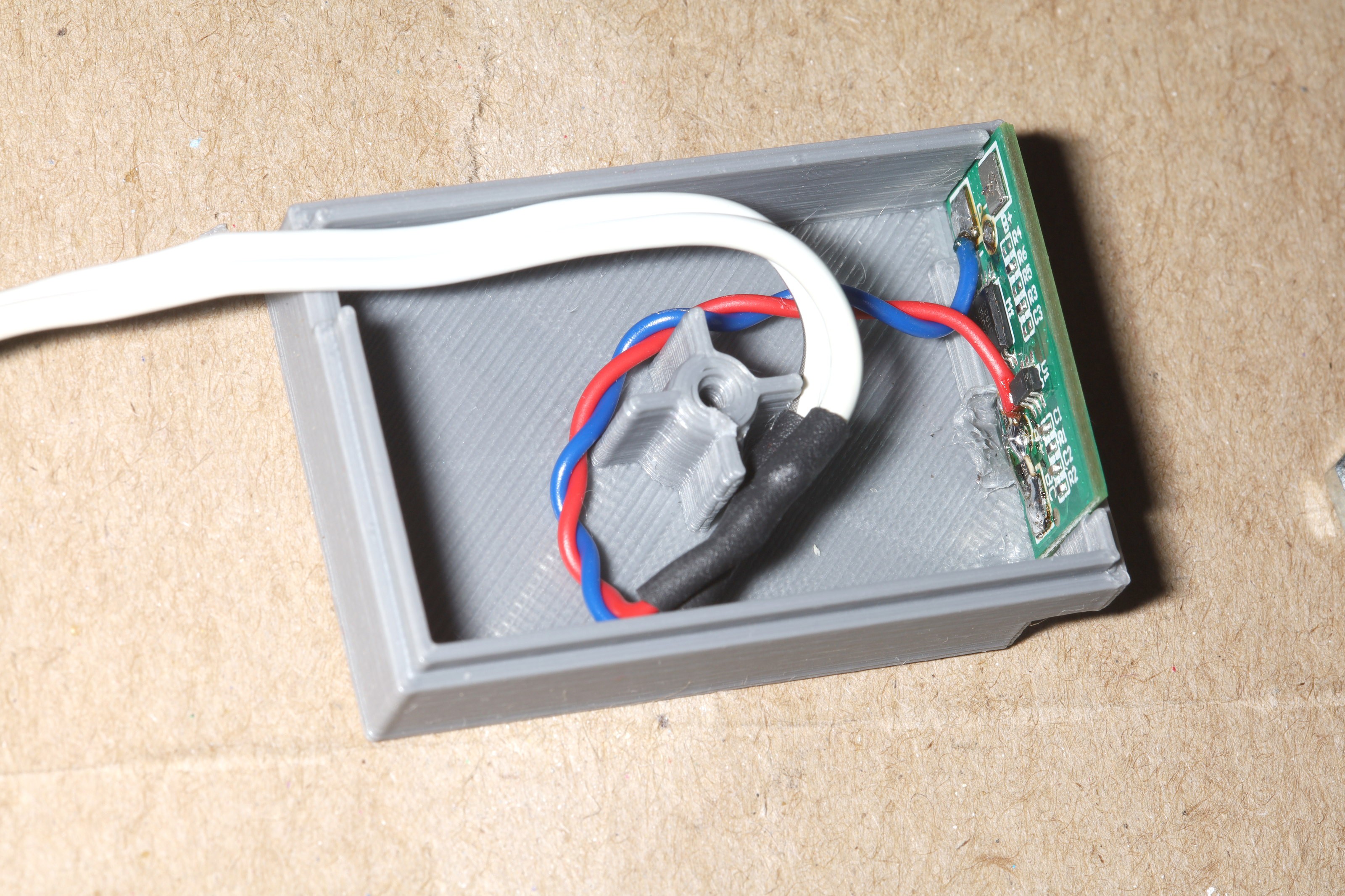
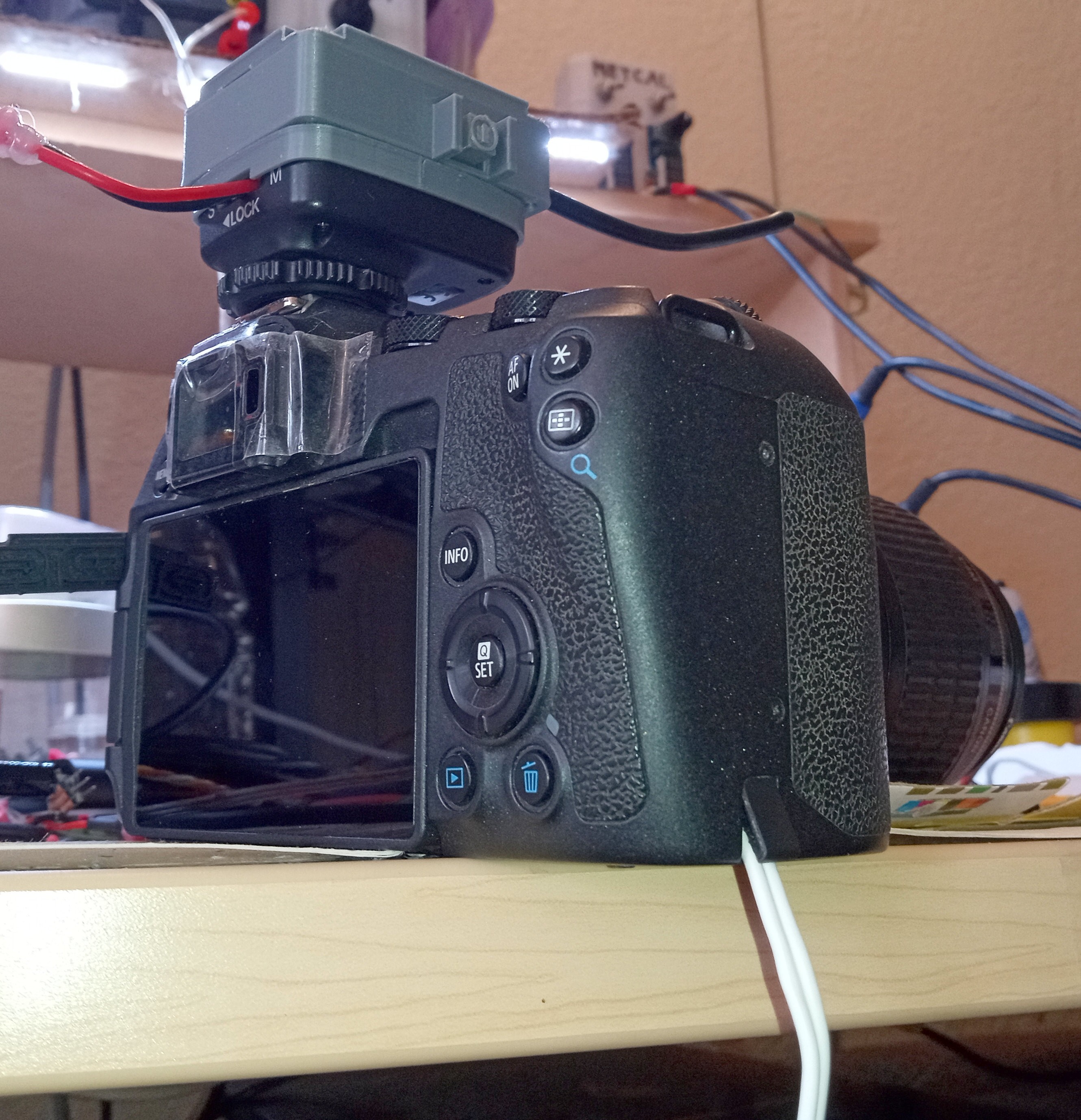
Then we have a minimal strain relief.
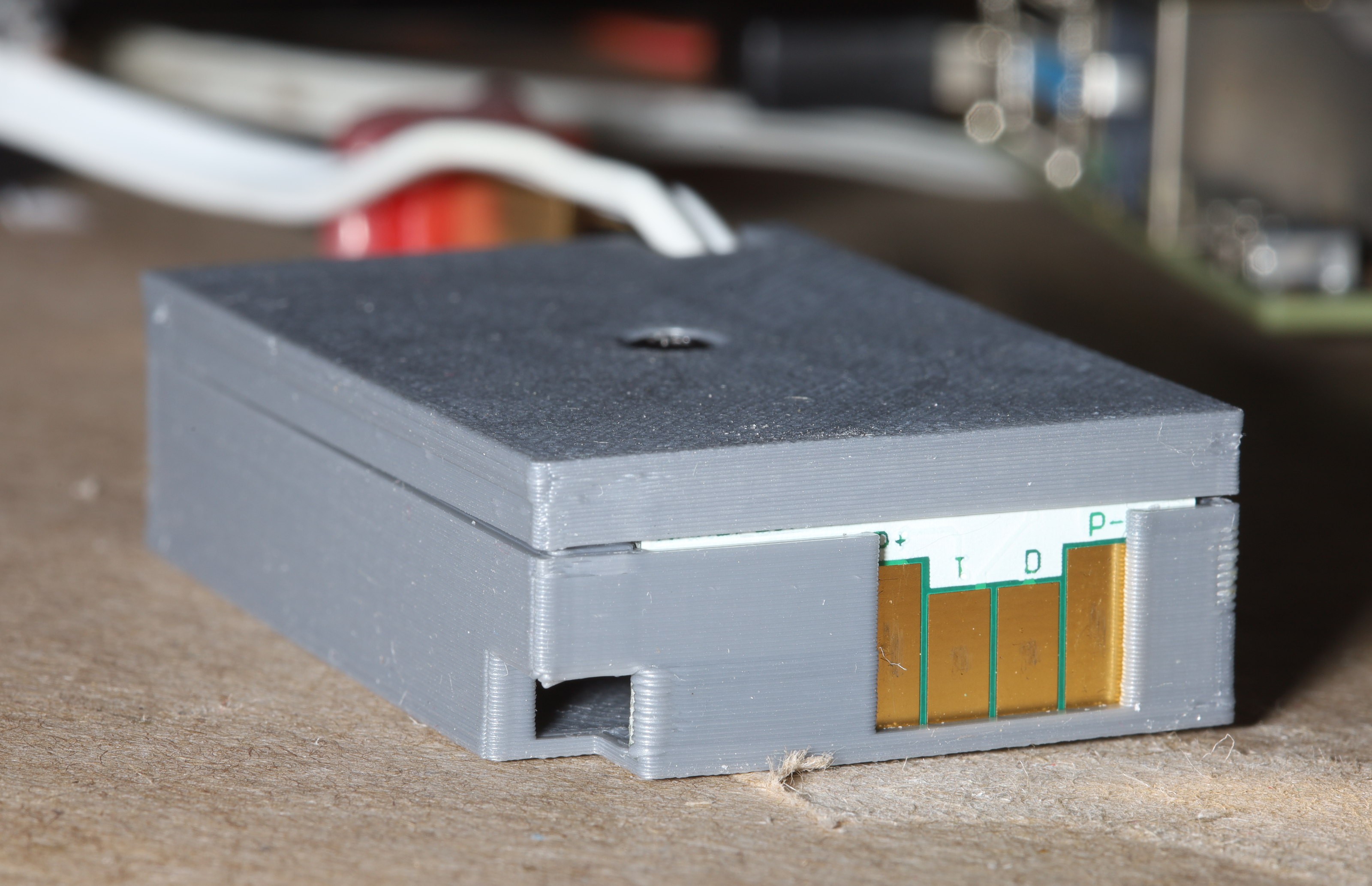
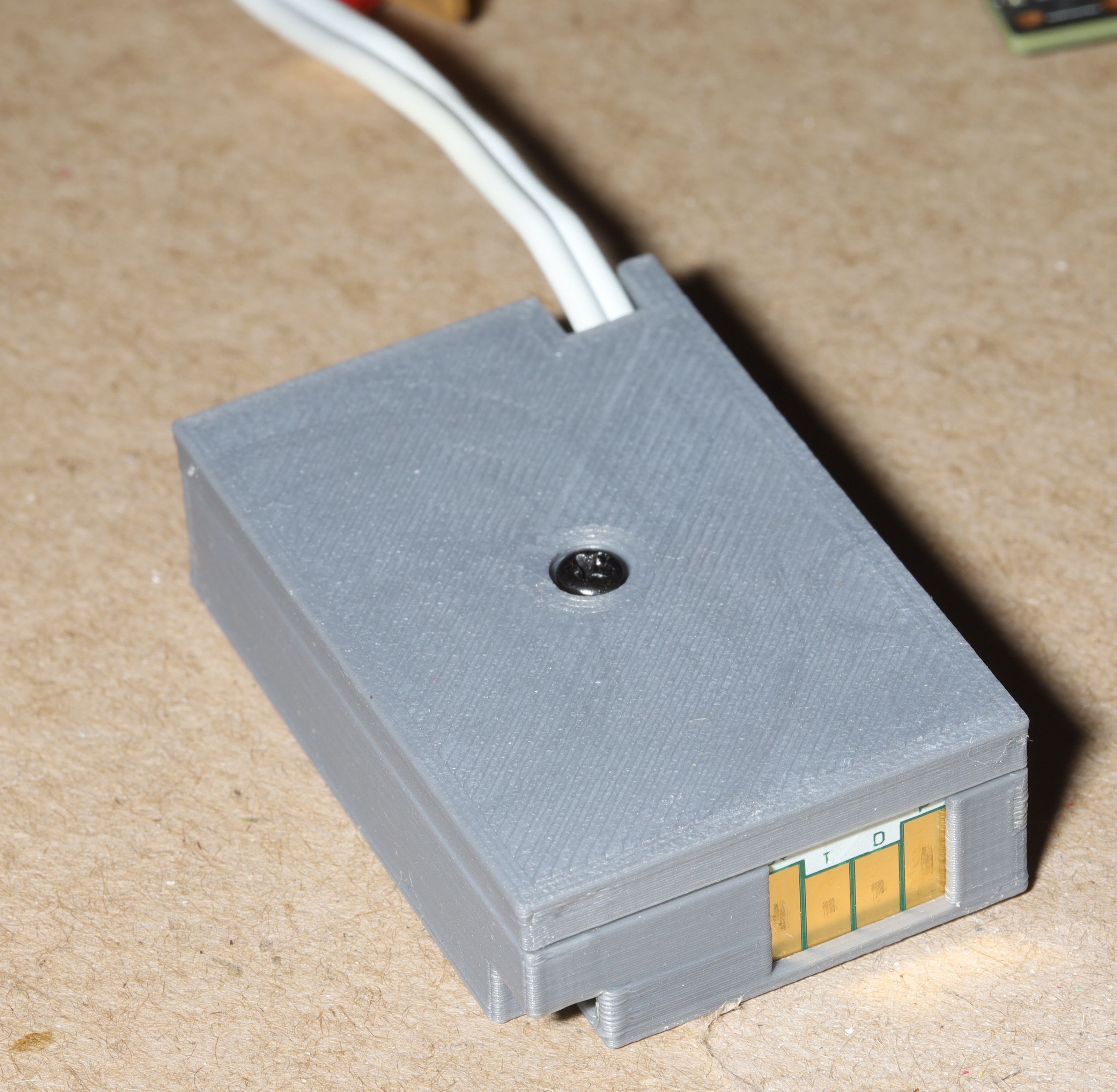
The model could use a hair taller enclosure & smaller board alignment fiducial, but the lion kingdom ran out of time.
It was a total waste of time compared to getting a $14 product.
https://www.amazon.com/Battery-Replacement-Mirrorless-Compatible-DP500III/dp/B08FHSRLY8
But it arrived a lot faster than snail mail.
Discussions
Become a Hackaday.io Member
Create an account to leave a comment. Already have an account? Log In.