Frank
Frank-
Mastering Technology - Fail Early
04/20/2023 at 11:29 • 0 commentsThis project GM-Study-Max only succeeded because I progressed through earlier prototypes GM-Proto-E1 and GM-Study-E1, before committing to the final and complex SMD design of GM-Study-Max.

GM-PROTO-E1 finished built In the 1st milestone GM-Proto-E1 project, I built a much simpler daughter board, purely in through-hole technology. It achieved three goals:
- Validate the connector measurements and PCB production is sufficiently precise.
- Check if I am able to solder the 276 pins at fine 1.27mm pitch reliably.
- Get a prototype board that exposes pins in standard 2.54mm pitch for easy testing.

GM-PROTO-E1 dimensions Because the PCB design is only using THT, a failure would not be costly since PCB manufacturing without SMD assembly has fast turnaround and is very reasonable priced. Being able to prototype with general-purpose IO THT components gives confidence for the final design before switching to surface-mount components. SMD parts are hard to test, specs are easily misread, and SMD production re-runs for mistakes increase cost and time.

GM-PROTO-E1 assembly The board layout has been created in KiCAD, which is ideal for such tasks.

GM-PROTO-E1 in KiCad Finally, Verilog code verifies the basic set of onboard components: 4 LEDs, 2 buttons, 4 switches, and 2 7-Segment display modules. A demo video is available here:
-
Training Lessons for GM-Study-Max
04/10/2023 at 09:18 • 2 commentsThe main purpose of the GM-STUDY-MAX board is student education in digital logic and FPGA code design. For this use case, sample lessons have been created that demonstrate the board is suitable. Below four sample lessons cover the introduction to digital logic for binary addition through adders:
Lesson-1 introduces the implementation of a 1-bit Half Adder
Lesson-2 uses the Half-Adder from Lesson-1 to build the 1-bit Full-Adder
Lesson-3 uses the Full-Adder from Lesson-2 to build the 8-bit Ripple-Carry Adder
Lesson-4 converts the 8-bit Ripple-Carry Adder into the Carry-Lookahead Adder
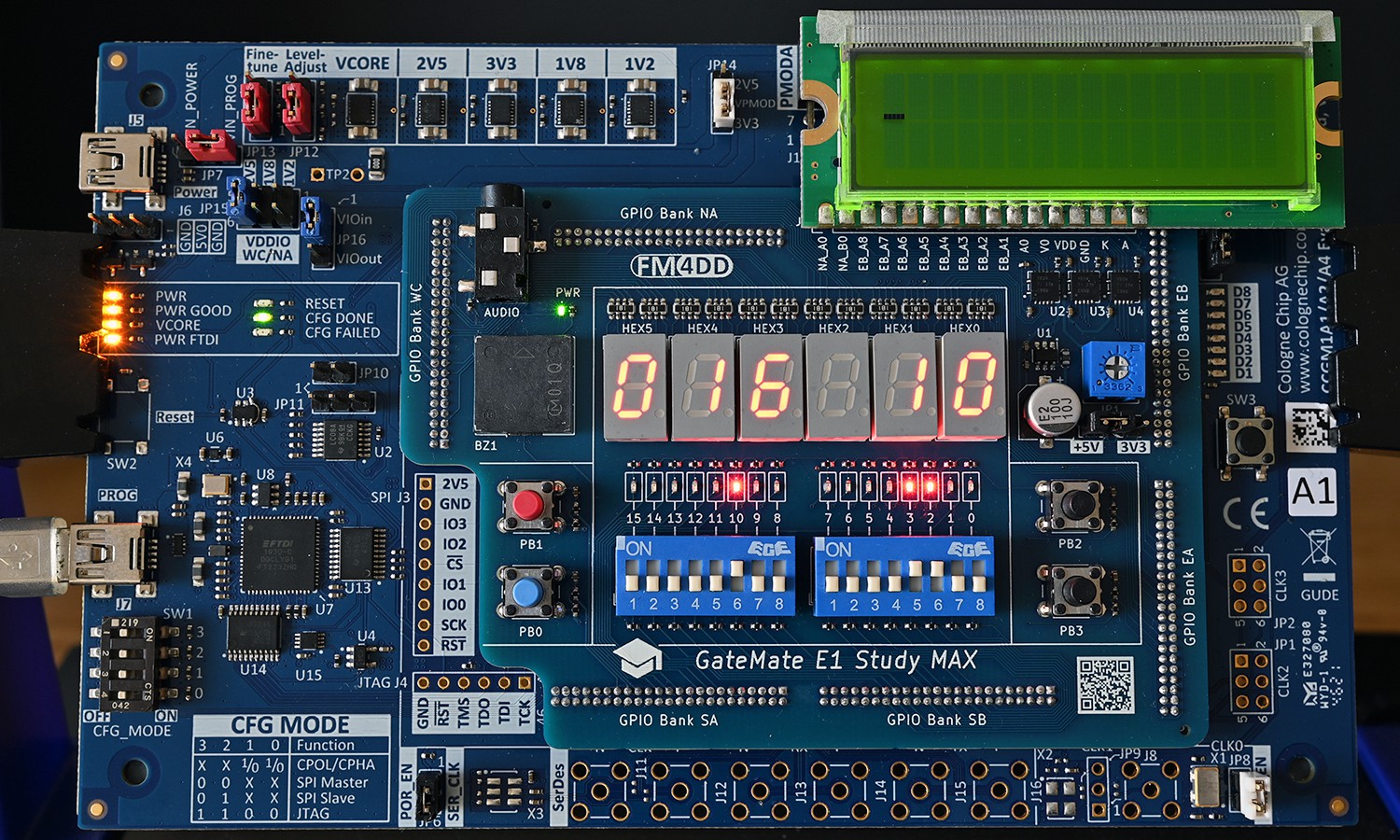
Here is a photo of running Lesson-3 on the GM-Study-Max board:
![]()
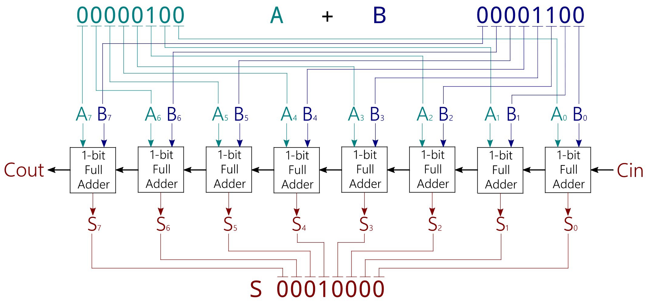
The board is running the 8-bit Ripple-Carry Adder logic, per logic design below:
![]()
The 8-bit Ripple-Carry Adder logic is implemented by using the two DIP switch modules for the 8-bits of A and B input. The output sum is shown on the 7-Segment display, both in decimal and hex.
![]()
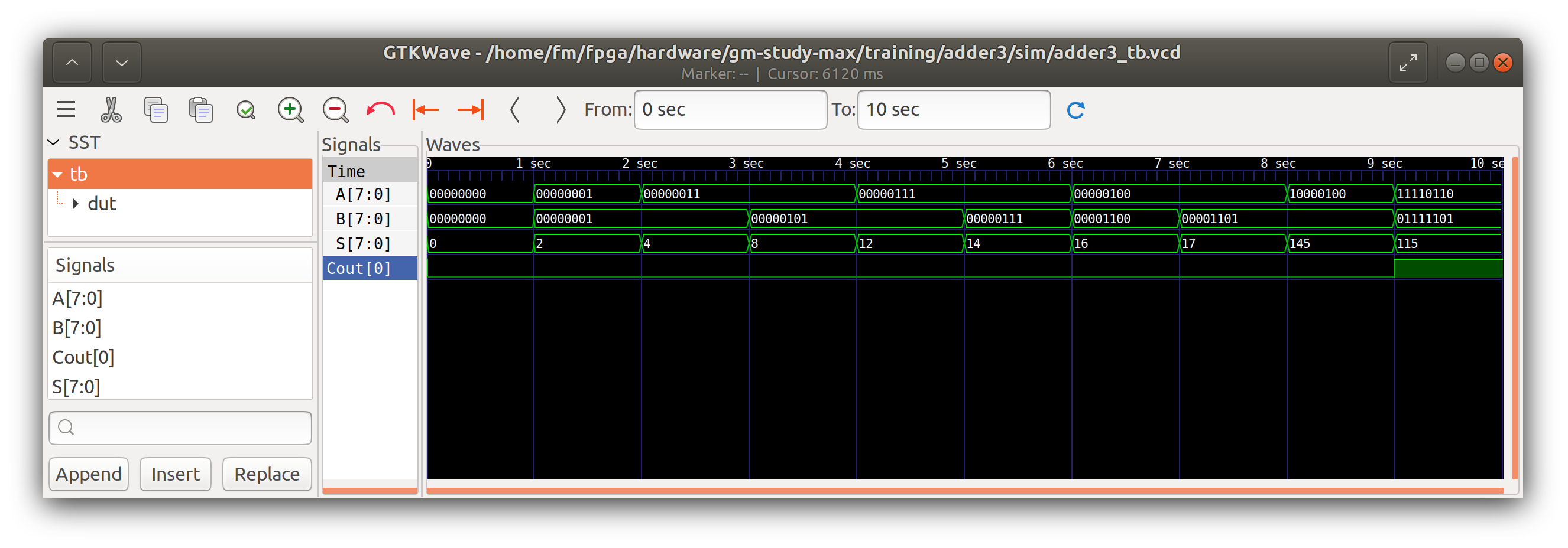
Finally, the iVerilog simulation testbench shows sample calculations in GTKWave.
-
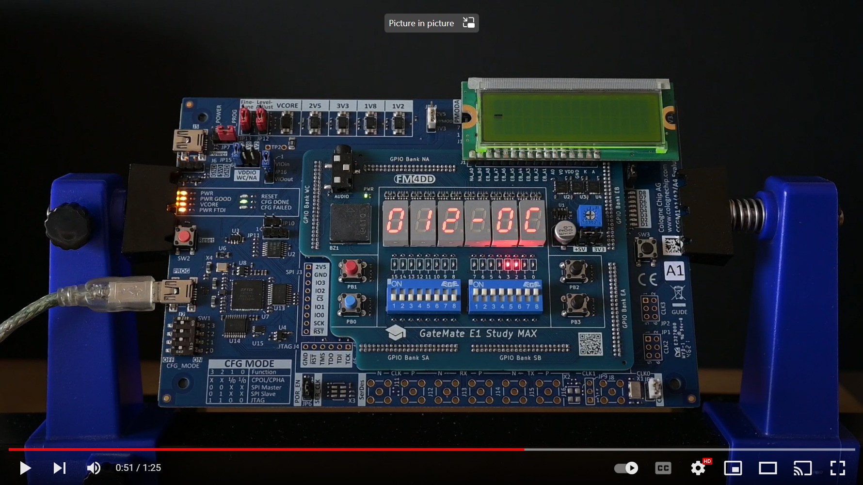
Demo Video available
04/02/2023 at 10:30 • 0 commentsA demonstration video has been created and uploaded to Youtube. It shows the execution of hardware test programs. The programs are located in the Github repository, under the examples folder.
The link is: https://www.youtube.com/watch?v=GMx3H4D8pCE
![]()
-
1st Set of Example Programs
04/02/2023 at 10:22 • 0 commentsExample Programs:
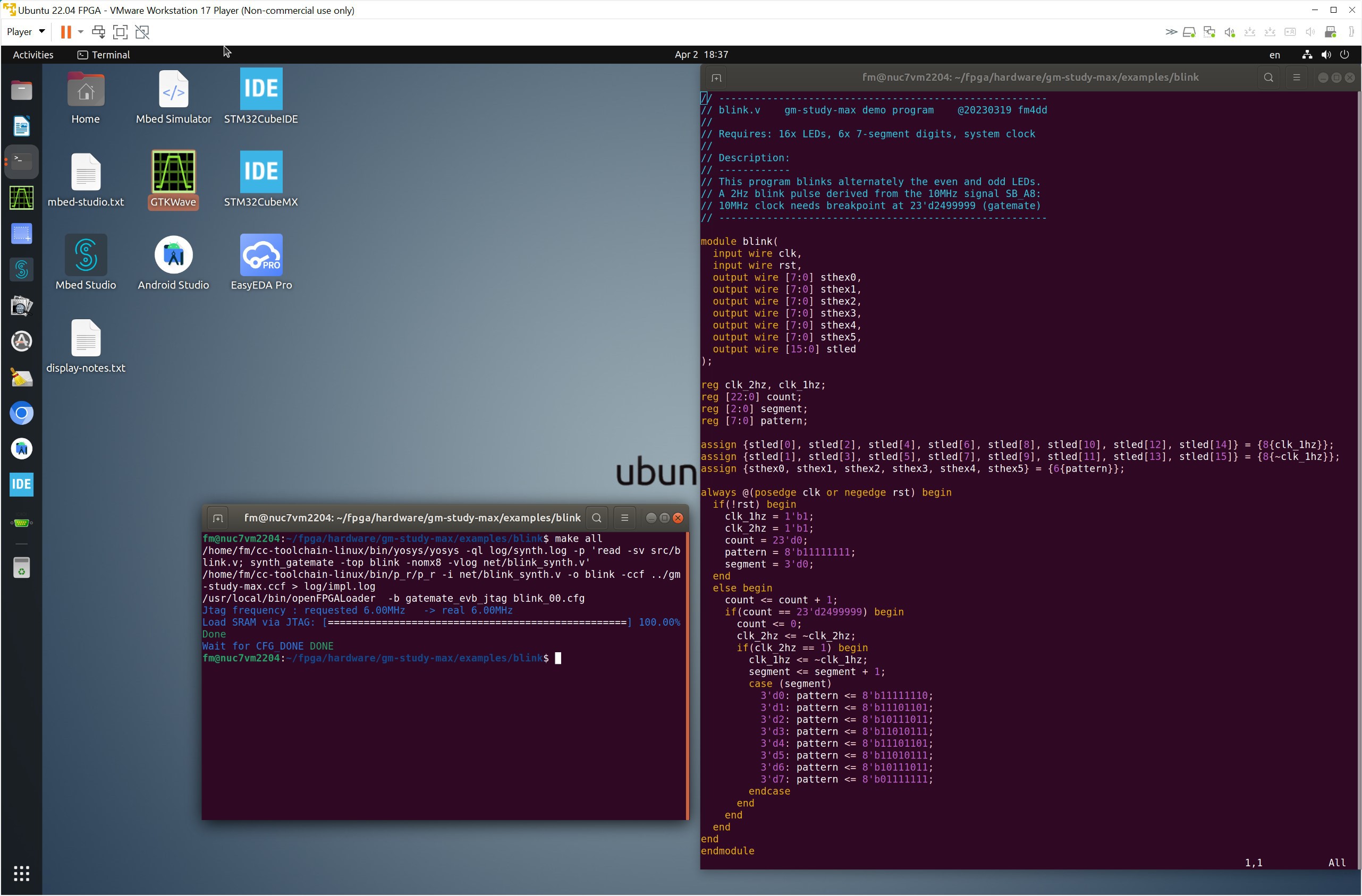
A set of example programs were written in Verilog, which demonstrate how to use the trainer board's hardware components under the Open Source toolchain. Below is a screenshot showing the workflow of editing the Verilog source code, and the 'make all' command in a different window doing the heavy lifting of synthesis, place&route, bitstream generation and upload to the board.
![]()
GM-Study-Max
Application module board for the GateMate FPGA evaluation board E1, suitable for computer science education and FPGA training.