deʃhipu
-
Servo Library
04/18/2023 at 17:44 • 0 commentsI finally made some progress on the library for CircuitPython for controlling the smart servos. For now I only have the basics, and I don't support SYNC WRITE (though I do have WRITE and REG WRITE, so you can move them all at once). But you can already set the id, set target, speed and time, and read load, position and voltage/temperature. That's basically all we are going to need. The code goes something like this:
import struct


class ServoBus:
    def __init__(self, uart):
        self.uart = uart

    def _chcecksum(self, data):
        checksum = 0
        for byte in data:
            checksum = (checksum + byte) & 0xff
        return checksum ^ 0xff

    def send(self, servo_id, command, data=b'', reply=True):
        buf = bytearray(len(data) + 5)
        buf[0:1] = b'\xff\xff'
        buf[2:4] = struct.pack('>BBB', servo_id, len(data) + 2, command)
        buf[5:-1] = data
        buf[-1] = self._chcecksum(memoryview(buf)[2:-1])
        sent = self.uart.write(buf)
        readback = self.uart.read(sent)
        #print(readback)
        if not reply:
            return
        b = self.uart.read(1)
        while b == b'\xff':
            b = self.uart.read(1)
        if b is None:
            raise RuntimeError("No reply")
        reply_len = self.uart.read(1)[0]
        reply = bytearray(reply_len + 3)
        reply[0] = b[0]
        reply[1] = reply_len
        reply[2:] = self.uart.read(reply_len)
        if self._chcecksum(memoryview(reply)[:-1]) != reply[-1]:
            raise RuntimeError("Bad checksum")
        return reply

    def ping(self, servo_id=0xfe):
        reply = self.send(servo_id, 0x01)
        return reply[2]

    def read8(self, servo_id, register, length=1):
        reply = self.send(servo_id, 0x02, struct.pack('>BB', register, length))
        return reply[3:-1]

    def read16(self, servo_id, register, length=1):
        reply = self.read8(servo_id, register, length * 2)
        return struct.unpack('>' + 'H' * length, reply)

    def write8(self, servo_id, register, *params, bulk=False):
        write_command = 0x04 if bulk else 0x03
        data = bytearray(len(params) + 1)
        data[0] = register
        data[1:] = bytes(params)
        reply = self.send(servo_id, write_command, data)
        return reply[2]

    def write16(self, servo_id, register, *params, bulk=False):
        write_command = 0x04 if bulk else 0x03
        data = bytearray(len(params) * 2 + 1)
        data[0] = register
        data[1:] = struct.pack('>' + 'H' * len(params), *params)
        reply = self.send(servo_id, write_command, data)
        return reply[2]

    def commit(self, servo_id=0xfe):
        reply = self.send(servo_id, 0x05, reply=False)


class SCS0009:
    def __init__(self, servo_bus, servo_id, reverse=False):
        self.servo_id = servo_id
        self.servo_bus = servo_bus
        self.reverse = reverse

    def set_id(self, new_id, permanent=True):
        if permanent:
            self.servo_bus.write8(self.servo_id, 0x30, 0)
        return self.servo_bus.write8(self.servo_id, 0x05, new_id)

    def set_torque(self, value, bulk=False):
        return self.servo_bus.write8(self.servo_id, 0x28, value, bulk=bulk)

    def set_target(self, value, bulk=False):
        if self.reverse:
            value = 1023 - value
        return self.servo_bus.write16(self.servo_id, 0x2a, value, bulk=bulk)

    def set_time(self, value, bulk=False):
        return self.servo_bus.write16(self.servo_id, 0x2c, value, bulk=bulk)

    def set_speed(self, value, bulk=False):
        return self.servo_bus.write16(self.servo_id, 0x2e, value, bulk=bulk)

    def get_position(self):
        value = self.servo_bus.read16(self.servo_id, 0x38, 1)[0]
        if self.reverse:
            value = 1023 - value
        return value

    def get_speed(self):
        return self.servo_bus.read16(self.servo_id, 0x3a, 1)[0]

    def get_load(self):
        return self.servo_bus.read16(self.servo_id, 0x3c, 1)[0]

    def get_voltage(self):
        return self.servo_bus.read8(self.servo_id, 0x3e, 1)[0]

    def get_temperature(self):
        return self.servo_bus.read8(self.servo_id, 0x3f, 1)[0]

    def commit(self):
        return self.servo_bus.commit(self.servo_id)
Next up is to get the walking code to use this, and then see what improvements we can do to it using the time/speed settings.
-
The Devil in the Details
04/03/2023 at 18:28 • 0 commentsWhile the new servos are mostly a drop-in replacement for the rc servos, there are still some considerations we have to keep in mind. The first potential problem is that I'm powering those servos directly from the LiPO battery, with voltage that is below the recommended minimal voltage of 4.8V. The analog servos didn't really mind, and a simple trick of increasing their driving frequency helped with any weakness problems they could have. But the new servos have an actual microcontroller inside. Will it work with the lower voltage?
A quick experiment shows that the answer is "yes". I tried them with voltages as low as 3.2V, and they seem to work perfectly fine. Of course that doesn't mean there won't be some problems related to this discovered down the road. I still might need to add a boost converter to the robot to provide a stable voltage.
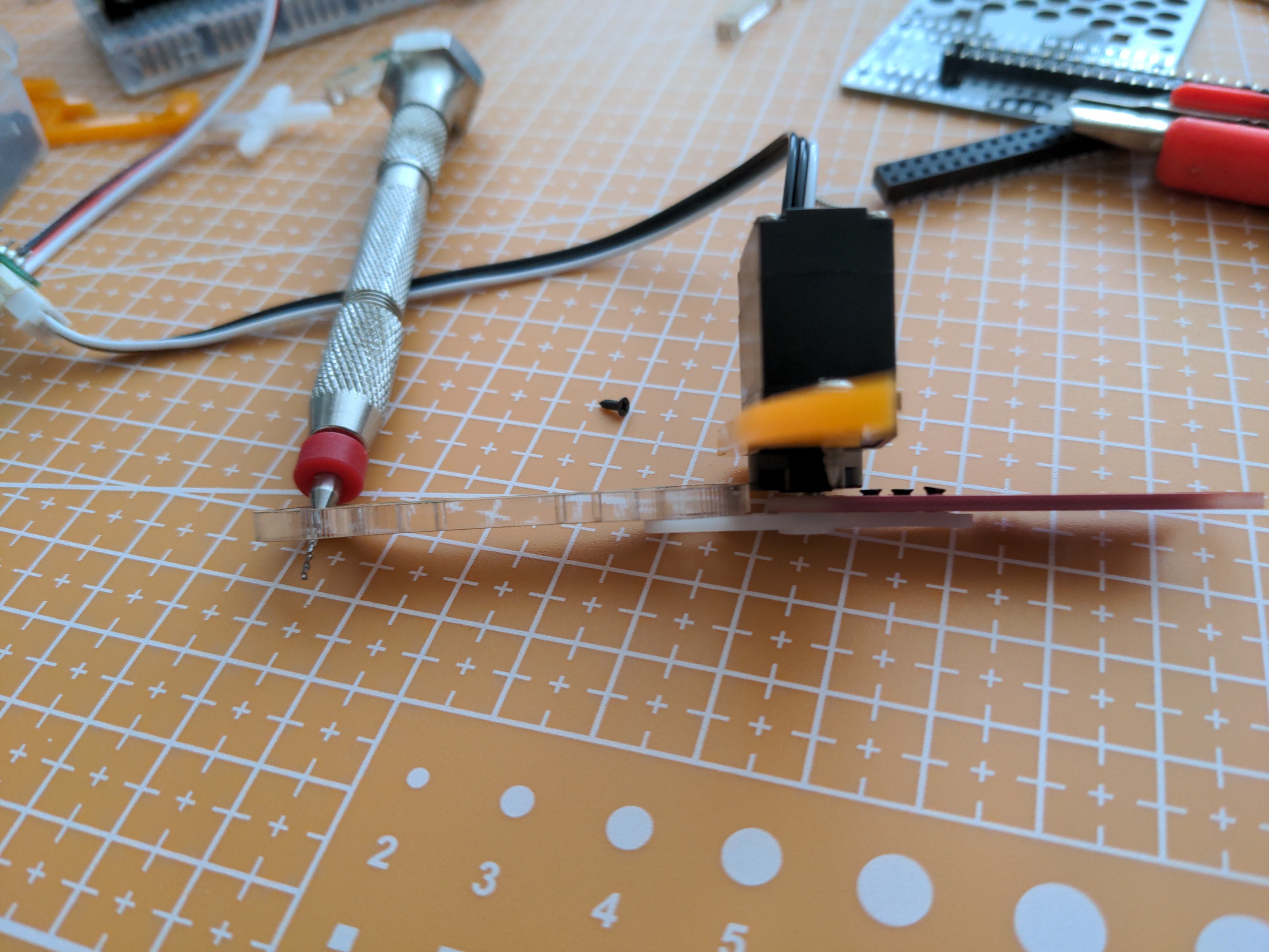
Another problem is mechanical in nature. While the case of those new servos has the same dimensions as those of rc servos, the output shaft is a little bit smaller and shorter. That is not a huge problem, as matching servo horns are provided, but turns out that the difference is enough that the 3mm thick laser-cut leg parts touch the servo case, which is adding unnecessary friction. I might consider cutting new leg parts from 2mm acrylic and with smaller holes for the horns, but for now I will simply use leg parts from earlier versions of the robot, which are made out of 1.6mm PCB that fits well enough.
![]()
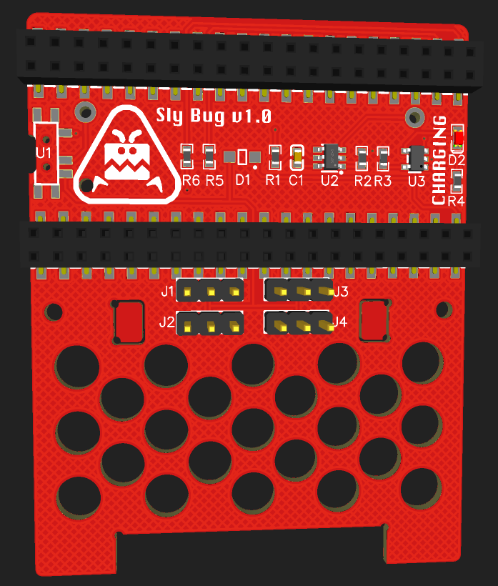
I also designed and ordered a PCB for the body, to connect the servos more conveniently. In the mean time I can just use the extension cables provided with the servos.
![]()
-
The Protocol
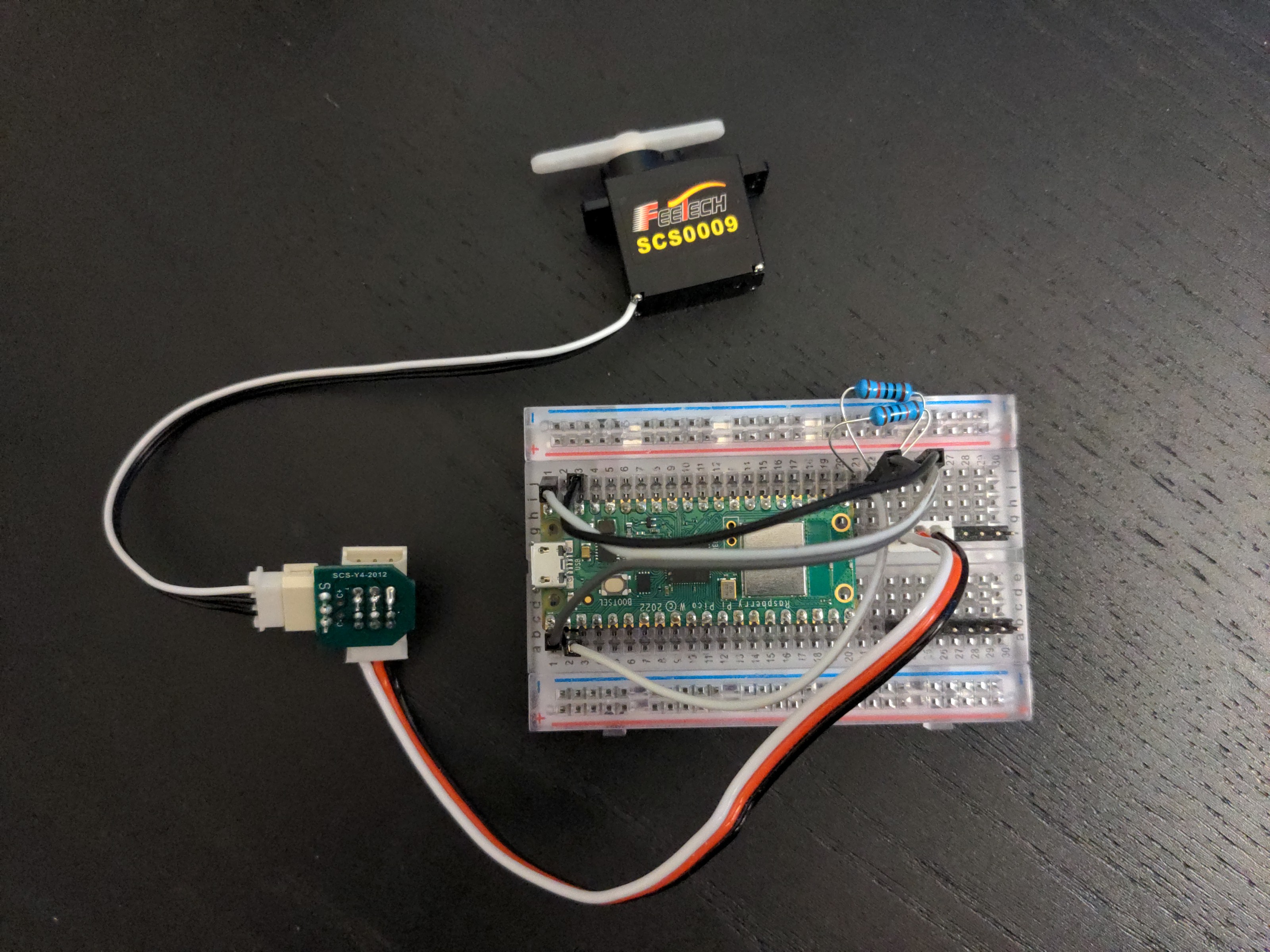
04/02/2023 at 19:50 • 1 commentTo talk to a smart servo you use a half-duplex UART protocol – meaning both RX and TX is done over the same wire, just not at the same time. The microcontroller sends a command, and then releases the pin and switches it to input to let the servo reply. Many microcontrollers have a special UART mode for this, but since it's not supported in CircuitPython, for now I just connected the RX and TX pins together with 10kΩ resistors (to avoid having a short when both sides try to speak at the same time), and ignoring the looped back data whenever we send anything. I decided to use a raspberry pi pico for this, so later on I may implement proper half-duplex UART with the PIO assembly. For now this will do.
![]()
The datasheet for SCS0009 specifies the baudrate for the serial as 1000000 – it seems strange, not being a power of two or anything close, but it seems to work.
Now, there is a higher level protocol on top of that serial communication. We send and receive frames of data, and those frames have a well defined structure. An outgoing frame looks like this:
- The first two bytes of a frame are 255 255 – this is to mark the start of the frame, but also to safeguard against missing the beginning of the transmission.
- The third byte is the ID of the servo – which can be from 1 to 254, with 254 being the broadcast ID that addresses all servos at once. Note that it can't be 255, so you can't confuse it with the beginning of the frame.
- The fourth byte is the length of the data that follows. This is so that you know how many more bytes to read from the serial connection before switching to output to send your reply, and so that you don't need to use timeouts for this.
- The fifth byte for an outgoing frame is the command. It can be 1 for ping, 2 for read, 3 for write, 4 for regwrite, 5 for action, 6 for reset and 83 for syncwrite. We will talk about those commands later.
- Then you send the parameters for the command.
- Finally, you send a checksum, calculated from the whole frame.
Once you send your frame, you switch to receiving, and wait for a reply frame. The reply frame has a slightly different, albeit similar structure:
- First you get the two 255 255 bytes.
- Then the ID of the servo that is replying.
- The length of following data.
- The status of the servo. This is 0 if everything is fine, but contains flags for different error conditions, like overheat or overload.
- Then come any parameters of the reply.
- And finally a checksum.
This protocol is share by all of the FeeTech servos, and probably many other smart servos out there. The examples in the documentation are invaluable for implementing the details, because they are not immediately clear from the descriptions.
Now that you have the higher level protocol, you will need one more thing: the register map of the particular servo you want to control. This is also part of the documentation, and it's different for the different models of the servos. The most interesting registers for the SCS0009 are:
- 0x2A tartget location
- 0x2C running time
- 0x2E running speed
- 0x38 current location
- 0x3C current load
There are of course many more, including settings that are saved in the internal EPROM for the servo ID, its PID parameters or safety protections. We will not need those for now.
Now, let's talk more about commands.
Ping is simple – it just makes the given servo send a response. It can be useful to test the communication, check the ID of the servo (if you only connect one and send a ping to the broadcast ID), or get its status.
Read and write let you get or set the content of the registers. The read takes the number of the register and the number of bytes to read from it (some registers are 2 bytes long), and write takes the number of the register and the values to write. Easy.
The regwrite is interesting, because it lets you schedule a change in the register without actually committing it yet. You can do it for several servos, and then when you are ready, confirm the change by sending the action command to the broadcast ID. This is useful when you need to move several servos together at once.
Reset is self-explanatory. It resets the servo to the settings it has saved in its EPROM.
Finally, syncwrite is a command that lets you send to the broadcast ID a big chunk of data, and each servo will fish from it the data for its registers. It's faster then the regwrite+action way, but basically serves the same purpose – moving all the servos together at the same time.
That is pretty much all we will need. I will be making a CircuitPython library with all of this stuff next.
Special thanks to Abby from FeeTech for sending me all the necessary documentation! I would never figure it all out myself.
-
Smart Servos
04/02/2023 at 09:48 • 0 commentsHobby servos were not designed for robots – they are mainly for remote-controlled airplanes and boats, and they were created back in times of analog radios, when PWM signal was the easiest to multiplex. While they are relatively cheap and convenient, in that they already contain the drive train, the motor controller and a position sensor of sorts, they are pretty lacking in terms of feedback. Yes, you can add wires to them to be able to read the position of the potentiometer or the power sent to the motor, or even add some current monitoring circuit, but it always requires additional components and the use of additional microcontroller pins, and gets unreliable and tricky when the servos are not powered with stable voltage.
But there are other servos, that were mostly designed for robots and similar constructions. Smart servos tend to be slower, with more torque, two-way digital bus communication, more convenient mounting options and brackets, and general sense of solidity. They however also tend to be rather bulky and expensive, and because I prefer to build small and cheap robots, I never really tried them properly.
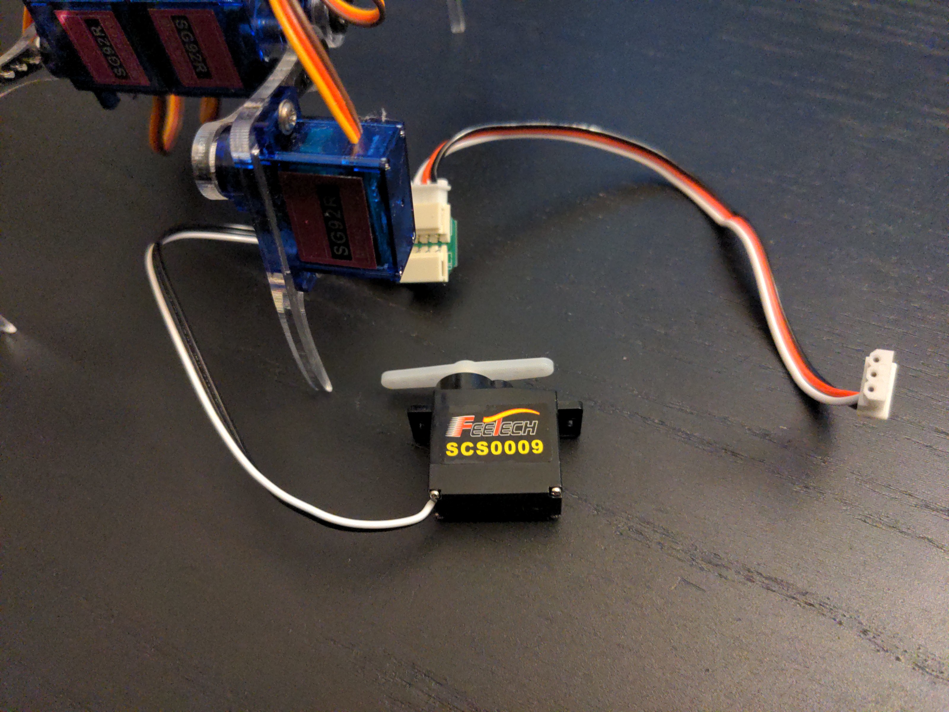
But recently I have discovered FeeTech SCS0009 smart servos, which contain all the logic of a smart servo in a package compatible with a nine gram hobby servo. Of course they are more expensive, but not so much that I couldn't run some experiments with them. And since they are a drop-in replacement for the hobby servos, I don't need to design a whole new robot for them, I can use all the mechanical parts of the #Fluffbug or #Moo Bug, and probably reuse the PCB as well. The only thing I need to implement is the new communication protocol. So that's the plan for now: a version of Fluffbug with smart servos in place of the hobby servos. And we will see where we can take it from there.
![]()