Kārlis
-
Springs, birds and spoons
05/05/2023 at 07:15 • 0 commentsWhile drawing frame in last of the big drawing attempts i observed the paper shifting. I guess movement being close to edge thus biggest leverage, having opposite movement directions on the sides, and doing so multiple times was the worst case scenario.
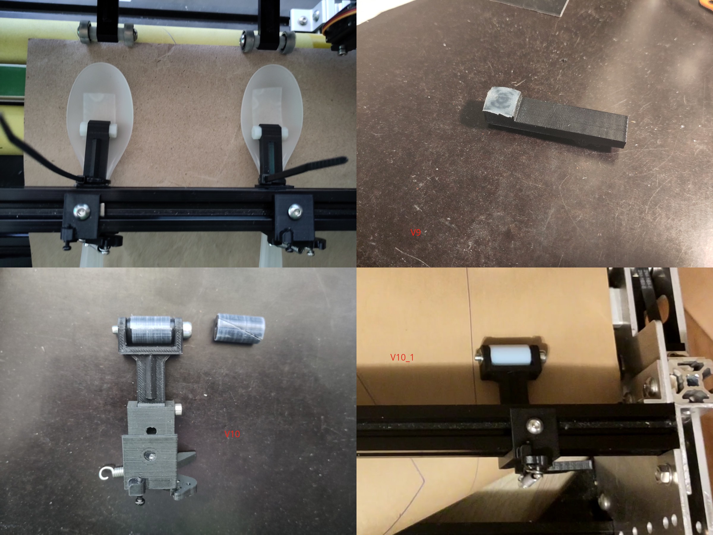
To minimize this I wanted to try increasing the force from top rollers. This made me return to making springs, but this time extension springs. Using a 3d printed jig after a little bit of practice I got somewhat decent looking springs. https://www.printables.com/model/468530-extension-spring-jig To better accommodate increased forces I beefed up some other parts of top roller mechanism, which accidentally made them look like birds.![]()
I didn't test yet how much it helped with that kind of paper shifting. But it seemed like the increased force made the problem of slightly misaligned top rollers steering paper sideways and thus bunching up between multiple rollers. I am not fully sure that the bunching up is caused only by misaligned top rollers and not the spiral wrapping of bottom rollers, or bottom roller misalignment.
First test to try confirming that the problem comes from top rollers was replacing them with plastic spoons. Turns out in the last few years single use plastic utensils have been more or less banned. I don't mind that, but it made this step a bit more trickier than I expected.![]()
Next step was making 3d printed arms with a spherical sliding pads, covered with HDPE tape for less friction. After testing it properly that was a failure. Unless I set the spring force very low, motor would skip steps. With pads pressing sufficiently lightly not to stall motors, even lightly holding the paper with a finger was enough for it to shift and rotate.
Iteration v10 was wider rollers wrapped in HDPE tape. Somewhat worked but bunching up was still a concern. In one of the tests I switched to a new crisp sheet of paper, from the old crumpled and flattened one. It started to work much better. This made me realize that there is a lot more to the paper rigidity than just g/m^2. Since the paper was cut from 700mm roll (and the plotter can handle maximum of ~690-680) I had to feed it sideways so that paper want's to up from left and right sides, instead of front and back like you would get if roll was sufficiently narrow to be fed directly. With the fresh paper things went much better than before, but as I was moving it back and forth at one point suddenly combination of way paper was curling and folding when hitting the wall behind caused paper to be pulled in folder over itself. The second lesson here was managing how ends of paper fold is important. Minor sideway pull from the paper folding badly can cause paper to be pulled in wrong and make a crumpled mess.
So I switched from having the plotter on my table, to placing it on pair of stools. That way paper can freely hang down on both sides without anything getting in the way. I guess I will also have to take into account direction in which paper wants to roll. This is slightly annoying because material often comes in 700mm wide rolls which is a tiny bit more than what plotter can handle and I will have to cut of a centimeter or two from one side.
In parallel with previous tests I had order some PTFE tubing. So that I can replace HDPE wrapped rollers with PTFE. That would not only reduce coefficient of friction but also eliminate seam which the tape wrapping had.Things to try out next:
- Actually test if changes had any effect on shifting while repeatedly drawing the big rectangle
- Make little shelves before and after rollers to help guiding the paper.
- Experiment more with using only one row of rollers when using a pen.
- Try increasing the spring force again
Bonus content:
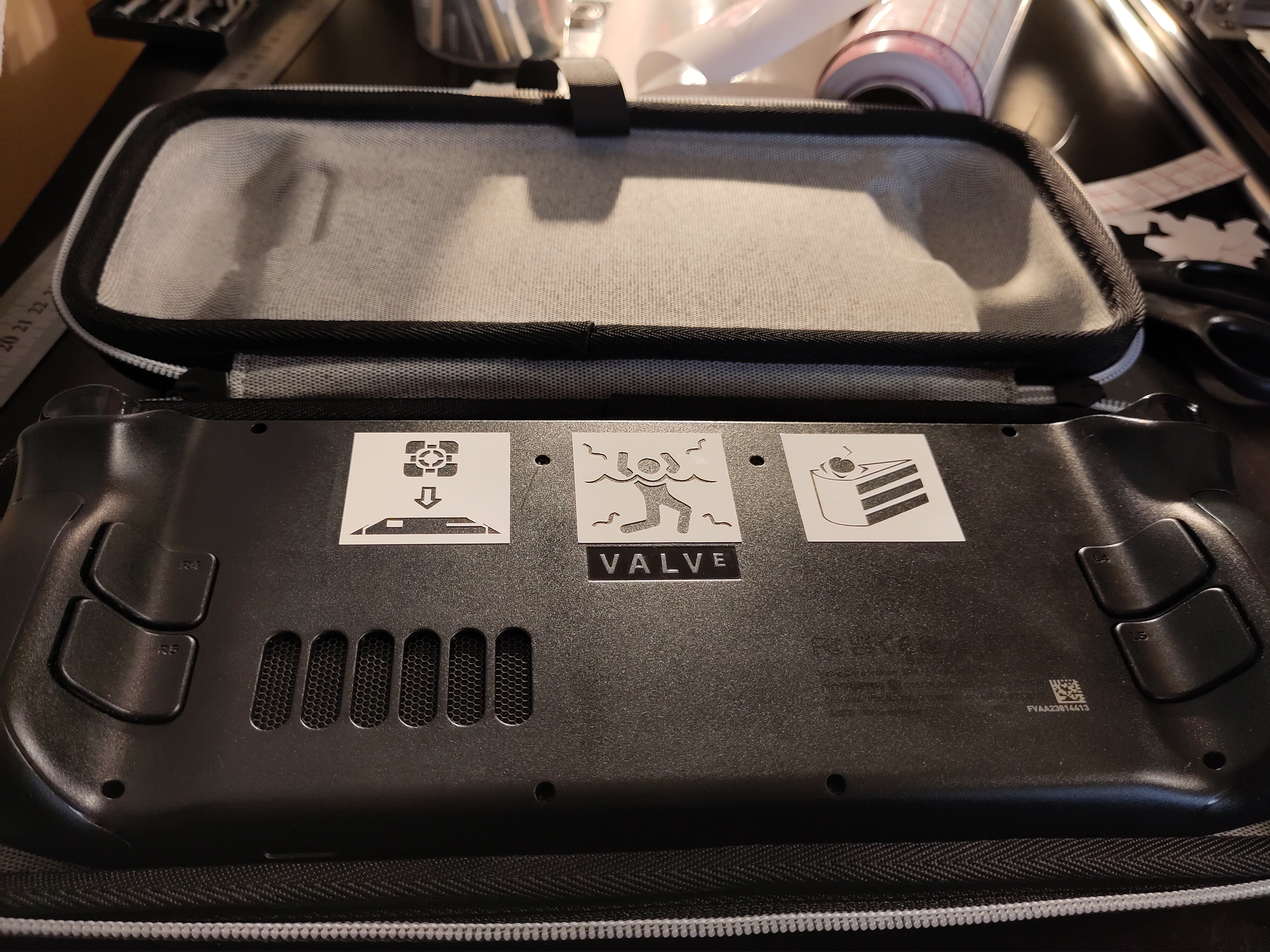
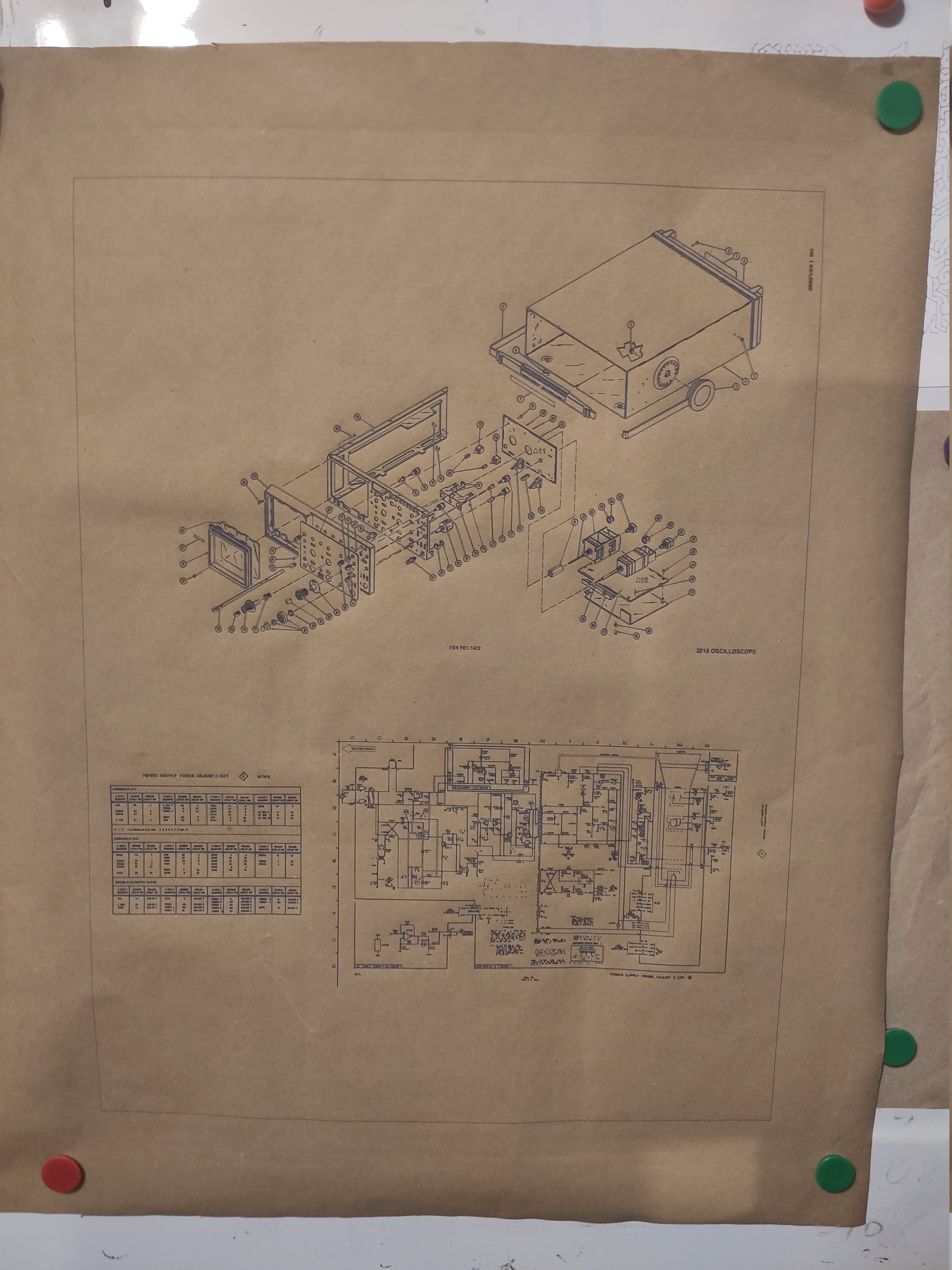
![]()
Some stickers 38mmx38mm each. An exploded view and one of schematics drawings for Tektronix 2215. Paper size 68x54cm. Margins could have been smaller but it was late already late and at that point I didn't want test how close to the sides I can get reliably.
![]()
-
Software
04/16/2023 at 19:59 • 0 commentsBonus video
The trickiest part was separating everything from cutting mat. Adding few more layers of tape, so that blade cuts only top layers helped.
Open the video in youtube if embedded version keeps buffering.
CAD
Hardware was design using FreeCad 0.20 , no assembly workbenches. With most of the parts being axis aligned and no complex swinging motion using a hierarchy of parts/transformation was sufficient.
Firmware choice
Controller board is using Marlin firmware and g-code. Why Marlin and g-code not some other firmware and hpgl or gpgl?
Due to the popularity of 3d printers there is wide variety controller boards for them available. Chose Marlin mainly because it supports wide range of controller boards and is actively maintained. G-code usage is mostly result of that. One thing that's slightly less convenient compared to others is that configuration is mostly done using compile time macros.
Klipper would check many of the same boxes as Marlin. For now chose against it, because having the controller board+RPi seemed like slightly larger complexity and at the time of source parts getting a Raspbery Pi was a problematic. Also with Klipper architecture it seemed somewhat wasteful to have more feature rich controller board, since with clipper some of it would be shifted to the RPi (or the alternative SBC).
RepRap firmware also seems nice, but the developers are focusing mainly focusing on their own high end Duet3d boards. While the support for some other boards in theory exists, they are not listed in the official reprap firmware website. Compatible boards link leads directly to Duet3d product page. I wasn't quite ready to buy in the ecosystem of their boards or running it on a board with unofficial support. I appreciate that some people where able to make a company around an open source project, even when any community contributions are almost non existing (more so than typical open source project)
Original Grbl project at this point seems more or less dead. But there a couple of promising forks each with slightly different goals and target hardware in mind.
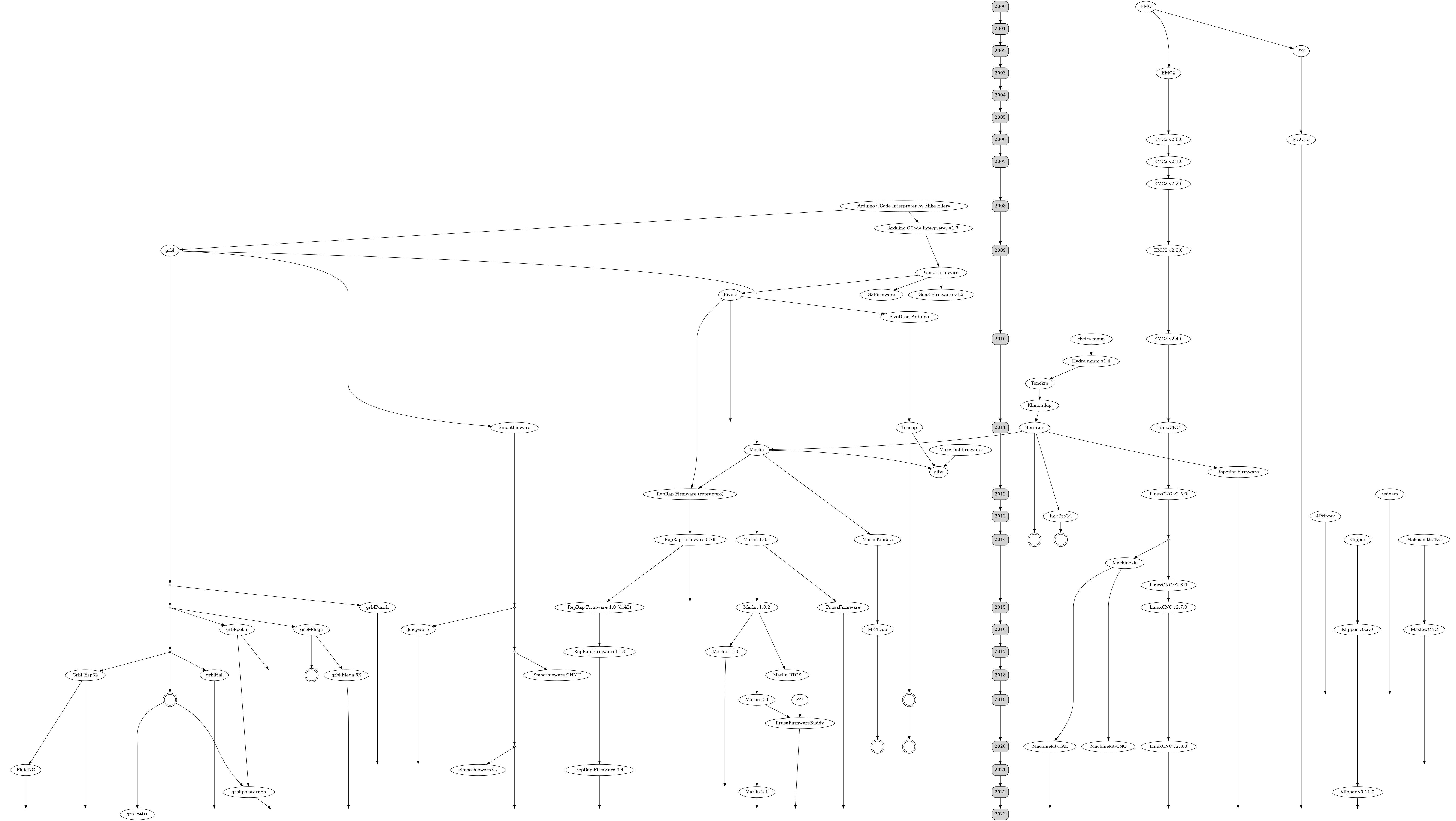
Thinking about all this led me into the rabbit hole of looking into what CNC and 3d printer firmware are out there and what is still being maintained. After cloning few dozen firmware repositories I managed to create this. I don't promise that it is accurate or exhaustive, especially early reprap project firmware history in 2008-2010 was somewhat messy. Due to small size it's hard to distinguish what's a new version, unique fork, or insignificant manufacturers modifications. Mach3 included only because it's early versions where supposedly derived from the same government funded public domain project that LinuxCNC also used.
(Click to make bigger)![]()
Marlin
Marlin is the firmware running on controller board. It is primarily targeted for 3d printers, but like most such projects it has some functionality for other kind of CNC devices.For the most part didn't have to do too much customization. Just disabled unused 3d printer functionality and configured 2 servos. Had to make some patches to fix compilation with only 2 axis enabled (no Z axis). Might be interesting too look into whether some of the spindle/laser code could be reused for the tool activation (lifting/raising), but for now I am just using M280 gcode directly.
- Fix compilation without z #24858 , thanks thinkyhead for cleaning up and extending the changes
- (not upstreamed yet) more no Z compilation fixes when backlash compensation feature is enabled
- (potential future changes) Would be nice to dynamically change servo wait time based on movement angle. Currently waiting for servo movements takes significant portion of time. Reduce wait time when servo moves just enough to barely lift above paper, would help.
InkCut
Inkcut is the software taking in SVG and converting to something that a plotter or vinyl cutter can understand (hpgl, gpgl or gcode) . It can be used either as standalone software or an inkscape plugin. But the plugin barely does anything, it mostly just opens the current svg in the standalone inkcut program thus saving you one or two clicks.
Inkcut required a bit more work to get in state where I am happy to use it.- make gcode output more configurable #348 . Allow configuring decimal places (required for metric machines using coordinates in millimeters) . Allow customizing gcode for lifting/lowering pen. Allow overriding startup sequences.
- minor UI number fix #350
- Fix some curve segments not being outputted #353
- #356 Improve path order optimization: use faster data structure for the greedy shortest path approach, add hilbert curve and Z curve path orders.
- #359 #364 Improve device creation/copying. Helps for having different presets for pen / drag knife.
- Run the unit tests on every commit using GHA (previously used Travis wasn't properly working anymore)
- (not upstreamed yet) #362 Filter improvements: new filter for joining lines and removing short gaps, new filter for removing short lines, repeat filter (useful cutting thicker material), more predictable filter order, fix blade offset curves for angles that aren't 90°.
- (potential future changes) handling of scale/output units needs to improved. Currently it happens too early in the processing pipeline making it difficulty to correctly handle units in some parts of code.
gcode senderAt the moment I am using pronterface for sending gcode to device. In theory could do it directly from Inkcut, but I don't fully trust it yet.
Useful Inkcsape extensions- Hatch fill There is also builtin hatch effect called "rough hatch", but I like this one better for tidy/non rough hatching.
- Remove empty groups -> does what it says. Often the output from other software exporting SVG or PDF is very messy. Cleaning up empty groups makes it a bit easier editing such files before sending to plotter.
- Remove duplicate lines
-
Design
04/10/2023 at 16:01 • 0 commentsFrame
The frame is mostly made from 700mm and 200mm 2020 aluminum profiles and various brackets. Then end plates where initially made with hand tools and a drill, but later versions are laser cut. This was still at the time when I tried to avoid 3d printed parts. If you are considering to reproduce project you might want to redesign them, to match the fabrication tools and techniques available to you.
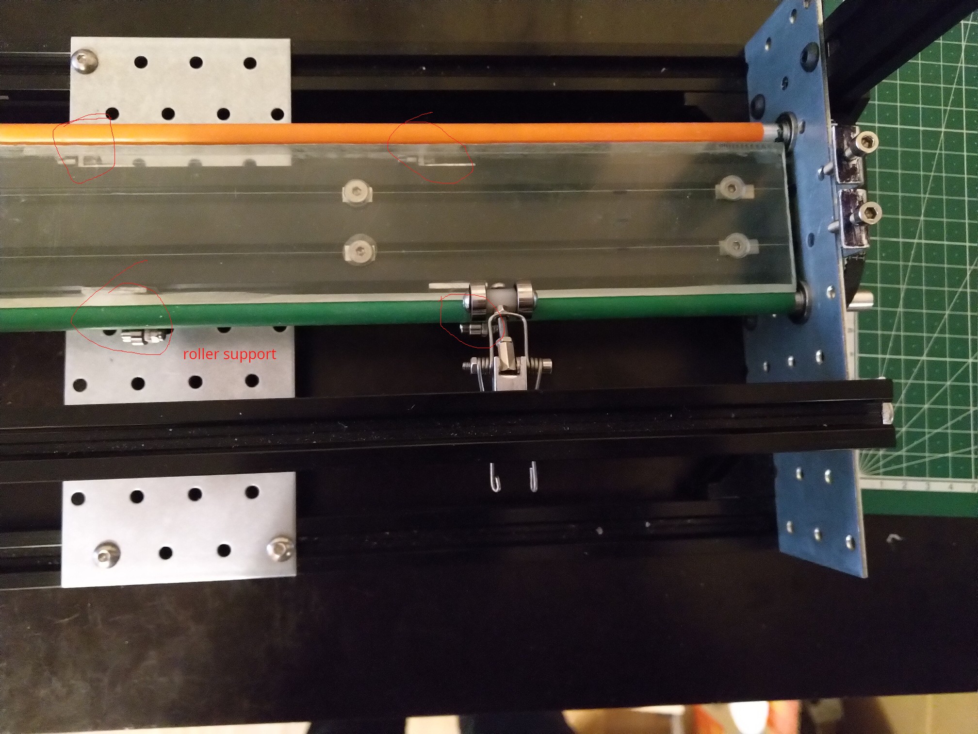
If you are considering to order them from a laser cutting service, they can be ordered as two pairs of identical parts. And afterwards cutting a rough hole in one of them for the motor.Drive rollers
![]()
Note I know that many plotters work push and pull with single line of rollers and it works assuming the rollers are sufficiently close to the tool, when using a thick material or light tool pressure. But the current roller size is limiting how close I can get support surface and tool movement line. And in some of the the earlier single roller tests (not having top rollers engaged) I did observe paper pushing up against the tool, which didn't happen when both side where pulling. I will be doing more tests to find out which combinations of material and tools need or don't need both rollers.
First version of drive rollers where made from 8mm aluminum rods wrapped in long balloons (the ones used for making balloon animals). Getting the balloon on the metal rod was a bit tricky. I tried soap water but it didn't work very well and also caused the rubber to spin more easily which is something you don't want. The method that worked best was: filling the balloon with air and letting it to sit for while, inserting tube slightly bigger than in the rod in the neck of balloon while its still filled, and then quickly inserting the rod through the tube before the air fully escapes and balloon fully shrinks. After quickly releasing air for short time balloon will be in partially stretched out state, in combination with any air that might get trapped it will help with the process. Once balloon is evenly stretched across the metal rod open cut open the end and push out any remaining air bubbles.
As mentioned before at 700mm length without support everything bends especially thin aluminum rod. So the every ~10-15 cm the rollers where supporter by pair small bearings. It was quite tedious to align all 12 of them.
Balloons where very grippy and worked well from that perspective. But they where quite fragile. One of the causes of it breaking was rubber gripping the paper better than aluminum resulting in it stretched and pinched. Other common cause of breaking was edges of support rollers cutting it.
After rubber balloons I tried rubber tube. Whatever the local hardware store had at appropriate size (probably pvc). It was more slippery than balloon, but that wasn't the bigger problem. After sitting idle for while both the top rollers and support rollers made dents in the spots they where resting. This caused rattling when the rollers where spinning.
I also tried wrapping the aluminum rod in various tapes, but that also was very noisy as the rollers crossed joints in the wrapping of tape. Those test pretty much eliminated the idea of bottom supporting rollers.
In the current version I switched to steel rods and placed a KP08 bearing block in the middle, which means ~350 mm of unsupported length. The bearing block in the middle increases the requirements for roller diameter to ~30mm. So the current approach uses 30mm aluminum tube with 3d printed endcaps wrapped in 180 grit sandpaper.
After thinking about this more, now that I have switched to larger radius tube, it flexes significantly less compared to 8mm solid rod. The middle support might not be necessary anymore.
Top rollers
Main purpose of top rollers is to press the paper or cutting mat against active bottom rollers without adding any additional friction or resistance.
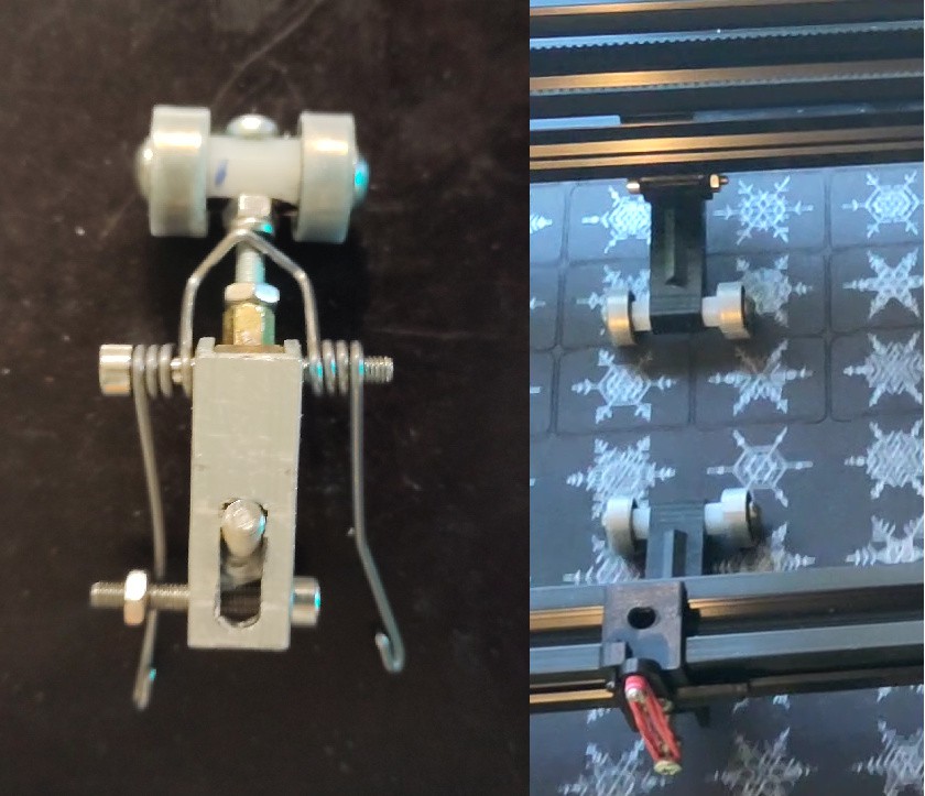
On the left one of the earlier versions using a selfmade double torsion spring and a pair of bearings. The mounting mechanism allowed adjusting the position left to right (based on current material size), front/back for positioning above bottom rollers, and rotating to align parallel with bottom rollers. Alignment with bottom rollers turned quite problematic. Even very small mistakes for the angle caused it to push the paper sideways. With multiple rollers each pushing in slightly different direction it resulted in paper bunching. It was a problem mostly for thinner paper, less for cardboard and cutting mat. Wrapping the bearings with UHMW tape to reduce the sideways frictions, seemed to help and reduce the bunching up. While it was possible to disengage the springs by unhooking the ends if not done carefully (which happened often) the ends snapping down could easily make a hole in paper. Other problem with this design was that changing x position ruins the alignment.
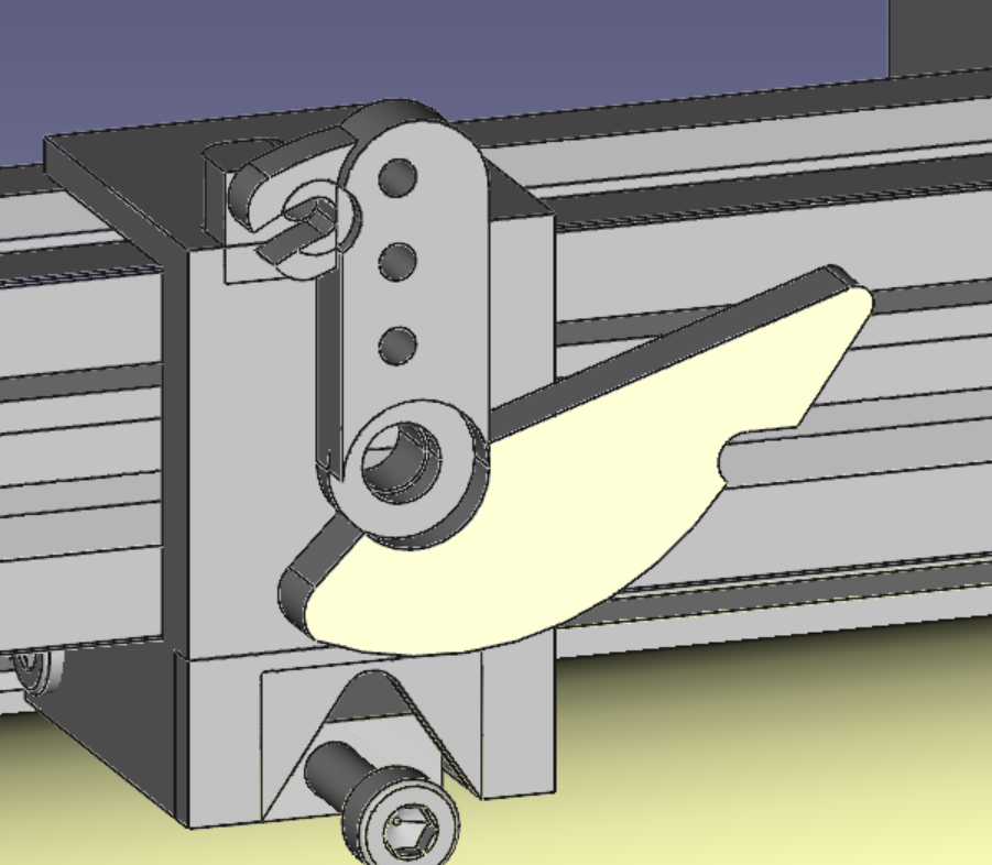
The later design uses a small lever for lifting/and lowering the arm with roller. Which makes it a lot more convenient to use. Torsion spring replaced with rubber pulling the end of arm with roller, a lot more similar to design used by some of the commercial vinyl cutters. It also makes it easier to adjust the force by doubling the rubber or using a different hole for the screw holding one end of it. Left to right position changes are also much easier because the whole roller assembly can freely slide sideways on the aluminum profile while the rollers are lifted. There is no angle adjustments, but combination of 3d printed parts being more consistent and possibly other factors seemed to make this less of a problem. Biggest issue with current design is that the bolt holding lifting lever gets loose sooner or later. Not surprising since using bolt for that purpose isn't really appropriate.
TODO: do some tests with softer top rollers. Most roller systems use soft rollers at least on one side as that increases contact are and thus grip. Soft roller would likely be less slippery than the current ones, thus possibly making the sideways steering problem worse, but the increased contact area with bottom rollers might negate this downside.![]()
Support surface
Between the the rollers there is a surface supporting the paper while the pen or blade are doing their job. Initially with the smaller rollers there was enough space for 20x40 profile but with the bigger rollers there is only space for single 2020 profile. It needs to be cut few millimeters shorter than 700mm based on the thickness of end plates unlike rest of the 2020 profiles used in the build. You can get 2020 profiles that have one of the 3 sides flat without the slot for T-nuts.
The top surface of it is covered with UMHW(-PE) tape. It reduces sliding frictions, and also saves the surface and blade when cutting without a cutting mat and blade depth is set too deep. Supposedly commercial plotters are using a PTFE based strip for even less friction. But UHMW tape seemed easier to get at least when I was trying to buy it. Search results for PTFE tape often being filled with thread sealing tape doesn't help. In some of cutting tests I even used cheap electrical tape, this probably isn't too critical.
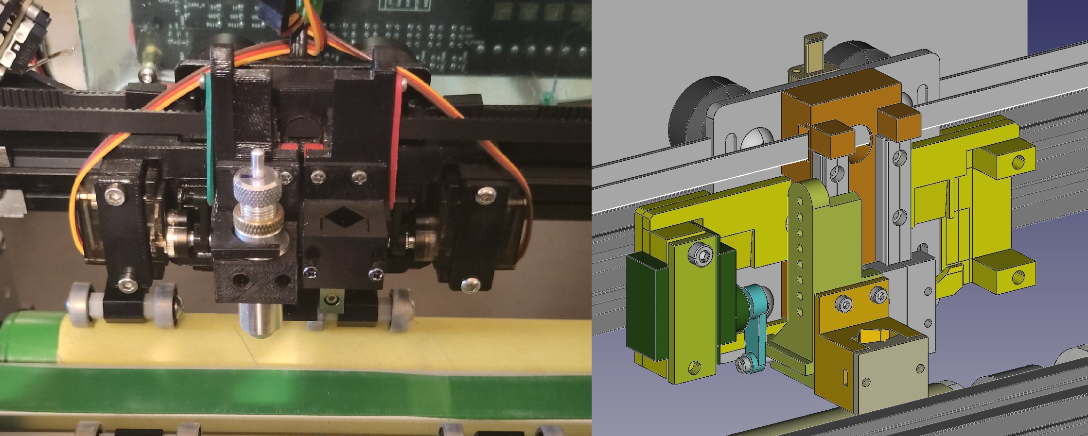
Tool head![]()
Tool head consists of two symmetrical parts allowing to use either two pens or a pen+blade without having swapping tools. Two halves are positioned as close as possible to each other to maximize the area covered by both tools. Up and down movement is performed by a small hobby servo.
Tool mounts are split in two parts. First part mounts to the vertical rails and contains everything related to vertical movement (holes for hooking one end of rubber, surface that servo pushes up). Second part mounts to the first part and hold the actual tool. This allowed designing the tool mounting independently from vertical movement part and also reduces the wear on threads in the linear bearing carriage as I keep swapping out different kinds of tools.
Due to limited width, tool mounts are not symmetrical and need to be mirrored depending on whether they are for left or right side. Having tools mounted off center somewhat negates the purpose of having vertical rails mounted as close as possible to each other.Servo arm supports the slider with tool from bottom and is also connected with a rubber. That way when pushing up force is transferred directly. But when moving down force depends on how much the rubber stretches. Main purpose of it is compensating for surface imperfections, cutting surface not being perfectly parallel to x axis and applying roughly fixed tool pressure based and how deep bellow surface you try to move it. As unintended benefit, in case of crash, force is limited by maximum stretch of rubber instead of motor holding torque or belt slipping.
In theory this allows adjusting force with software. Although wider range of force can be more more easily achieved by physically changing the configuration of rubber (number of rubber bands, on which hole the end is hooked, making multiple loops). For maximum speed you want the vertical movement to be minimal, barely lifting the pen above paper, and moving down only enough to compensate lack of flatness, and generate most of the force with preload.
Near the end of servo movement range movement is almost perpendicular to the vertical forces. This gives a mechanical leverage reducing required holding torque for a fixed force and increasing maximum force available. End of the movement range is also the point where you need the most force, since it is proportional to the stretch in spring/rubber. As with any mechanical leverage it comes at the cost of increased travel distance. When using a pen which doesn't need as much force, you can position it in the middle of movement range where the vertical speed is highest.I considered using an approach where single stepper motor controls vertical movement similar to how LumenPnP https://github.com/opulo-inc/lumenpnp/ does it, but decided against it.
- Single stepper motor is much heavier than 2 hobby servos -> more weight harder to accelerate
- requires a limit switch, and homing procedure
- moving the z axis in either direction results in one of the tools moving one of the towards surface, safe state is in the middle of range. This complicates software to operate safely without crashing a tool.
One more different approach that was considered was using solenoids for vertical movement. They could potentially provide very fast movement. Solenoid might also remove the need for rubber/spring based joint. Maximum force rapidly drops outside the end of range. Most of the solenoids are not rated for continuous operation, meaning you either have to run them at low current further decreasing force or use a beefy one which would be somewhat heavy. It might be possible to improve it by using maximum current only during initial energizing and then decreasing it during continuous movement. Although the current is necessary not only for holding it in position but also applying enough force.
An alternative to controlling force with a spring or rubber is gravity. Its much easier to get fixed force using a matching weight and it isn't affected by vertical movement or material thickness. Major downside to this is that the weight needs to be accelerated along x axis during movement. This might be fine for many pens or fine liners that need barely any force. Some quick tests by trying write on kitchen scales indicate that many of them work well in 15-60g range. But some ballpoint pens or making a thick line with pencil can take 120-160g. And cutting vinyl or cardboard with a blade can take the equivalent of 200-600 grams of force or more. Attaching 0.5kgx2(for two tools) just as weight is not something I would like.
I should probably experiment a bit more with weight based approach for pens. Luckily the current design permits that by simply removing rubber, and hanging some weight on the end of pen. I wonder whether the small forces that I could get away with while writing by hand would work reliably for plotter. It might take a bit more force to prevent. Humans have the benefit of adjusting based on what they see and sometimes even repeating.
Electronics and wiringNothing exciting here. For now using a BTT octopus as the controller board. It's an overkill, but since I initially wasn't sure about all the details, wanted to make sure there will be plenty of extra pins. The wires for tool servos are held in air using a pair of 1.75mm 3d printer filament. The plastic filament retains some of it's shape from previously being on spool, it requires a bit of trial and error to choose correct mounting direction so that it bends without tangling up.
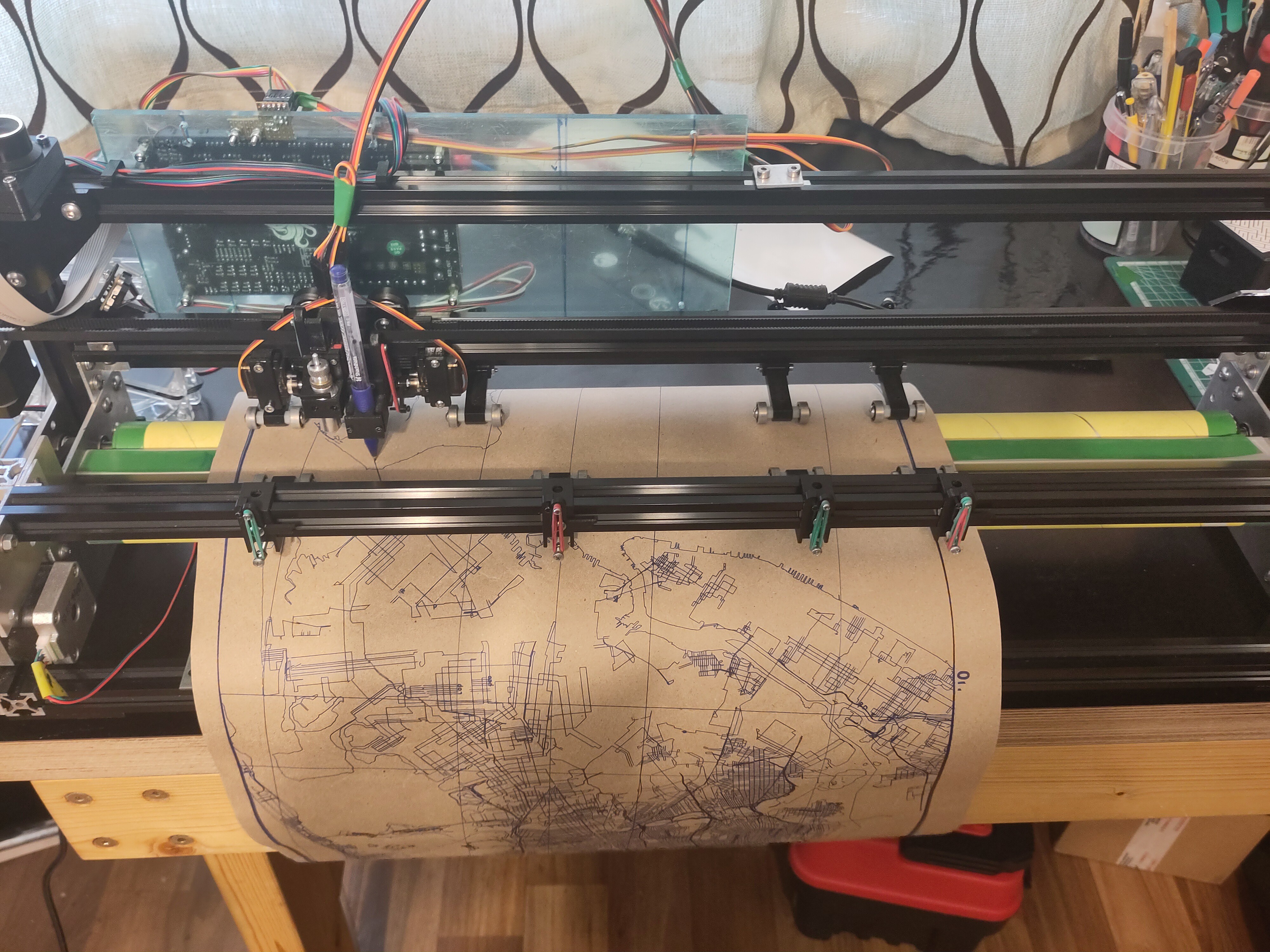
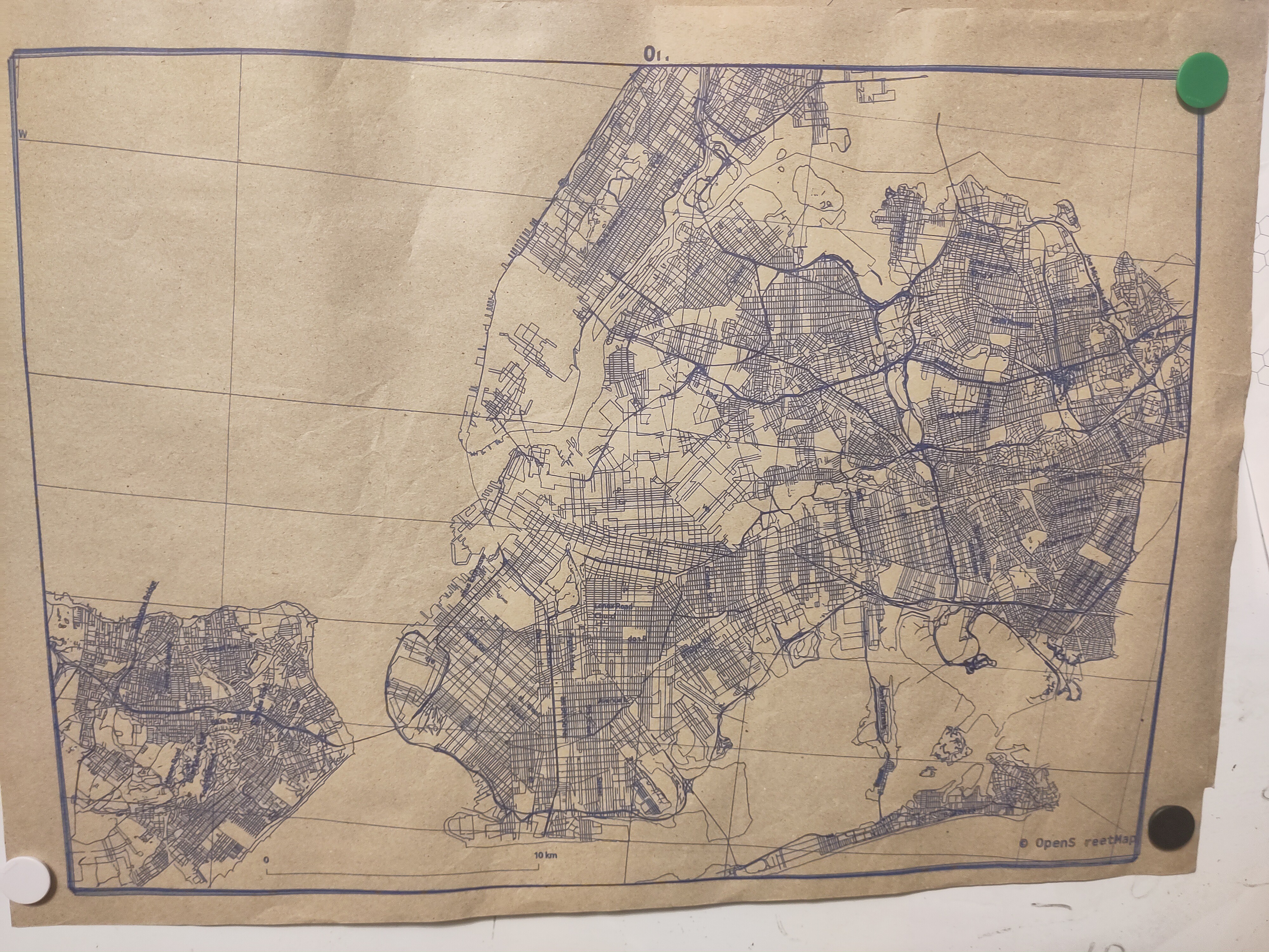
Bonus picture1:100000 A2 map of New York. At the start when drawing frame, position shifted by 5mm, didn't observe additional large shifting during rest of the job. Will have to try repeating it, as this isn't the first time when shifting happens during initial frame drawing.
70% into the job, servo died. It was one of cheapest servos available so I am not too surprised, although I hoped it to last a bit more.![]()
![]()
-
Upcoming posts and motivation
04/05/2023 at 21:22 • 0 commentsMotivation and other existing solutions:
If you have a practical usecase for any kind plotter this project isn't for you. Unlike with 3d printers where you might argue that a $1000 voron in some categories outperform commercial offering at similar price category, the market for various kinds commercial plotters and vinyl cutters is much more mature.
Small size (~300mm work width) vinyl cutter costs $150-$500 and should have good performance and reliability in a user friendly package. Should work great for small size vinyl cutting and other crafts projects.
Large size (500-1000mm) vinyl cutters. There are models available in the $300-$1000 range. Might not be the best thing out there but probably still better than any DIY solution. Less suitable for misc crafts projects. While the price is still somewhat accessible there is little reason for hobbyist to buy one unless you have very specific needs.
Hanging plotter designs. Very simple and cheap to make, large working area. High spped and acceleration may cause the tool to swing around due to being partially constrained by gravity. Unless very carefully designed positional accuracy might suffer as the amount of string on spools vary. Very compact when not in use.
DIY and semi DIY pen plotters with cross or H style X/Y axis. In some categories one of the better options for plotter art kind of stuff. Can be relatively simple as a DIY project. Making the tool reliably move (for a DIY devicee) in X, Y direction is much easier than any kind of roller based system. Also not a bad option for medium/large size plotter art stuff. Probably the biggest downside is that it takes as much table space as the paper you are drawing on. Although when not in use cross style designs like Axidraw can be somewhat compact, might be even possible to create one which easily disassembles or folds when not in use. Since the paper isn't moving as long as steppers don't skip steps (which shouldn't be a problem for reasonable speeds) there shouldn't be any shifting during drawing. If necessary you can lightly tack the corners with little bit of tape. No risk of smudging from the rollers even if you are using slowly drying ink. No fussing with cutting mat being too sticky or not enough sticky, or paper jams. Unlike roller based systems thickness of paper shouldn't be a problem, both very thin and very thick paper should be fine.
How is this project worse than everything listed above:
In terms of cost this project is probably more expensive (at least when taking into account money spent on iterations) compared to all the commercial solutions listed above.
In terms of performance and ease of use, one of the 3 options above will probably be better (assuming you know your usecase).
Reliably moving paper back and forth with rollers isn't easy. I am still fighting with occasional shifts and some kind of backlash like direction dependent offsets. Also thinner paper without a backing mat tends to bunch up or otherwise crumpling. As much as people like to laugh about inkjet printers being unreliable, I am starting to feel much more respect for their designers.Top rollers introduce risk of smudging the drawing.
Initial design goals/wish list:- be able to draw on A2 sheets (at least with thicker materials) ✔️,
- be able to work with material from rolls (at least with thicker materials) -> not tested
- 25 inch width -> should fit ✔️,
- be able to work with thin <80g/m2 paper without cutting mat -> unclear whether I will succeed in this
- no 3d printed parts -> ❌ failed
- usable for cutting vinyl stickers, paper and thin cardboard ✔️,
Future posts TODO:
More detail descriptions of current design and early failed iterations
Cleanup the CAD model from third party components with unclear licensing and publish it
Software
Demonstration of test output
- BOM
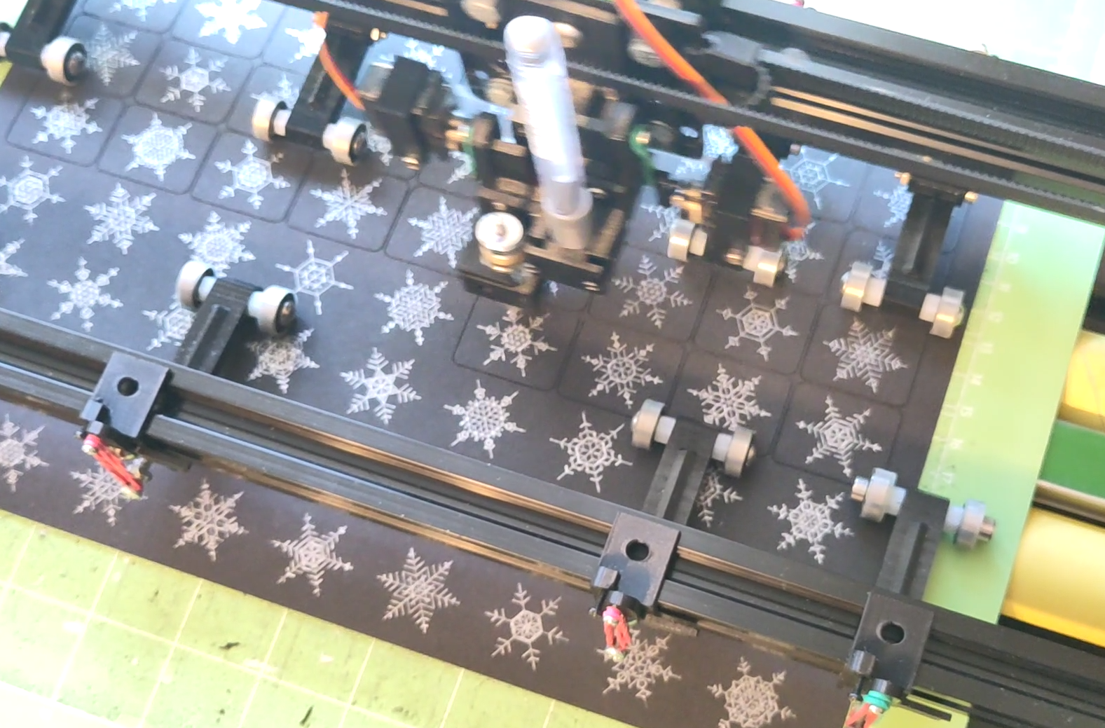
Bonus picture. Drawing and cutting a devilish winter themed memory matching game. Snowflakes generated using tool made by https://revdancatt.com/![]()
Big roller based plotter/vinyl cutter
~700mm plotter with roller based Y movement