 Sergej Stoetzer
-
1Simple Eyetracker (primary schools)
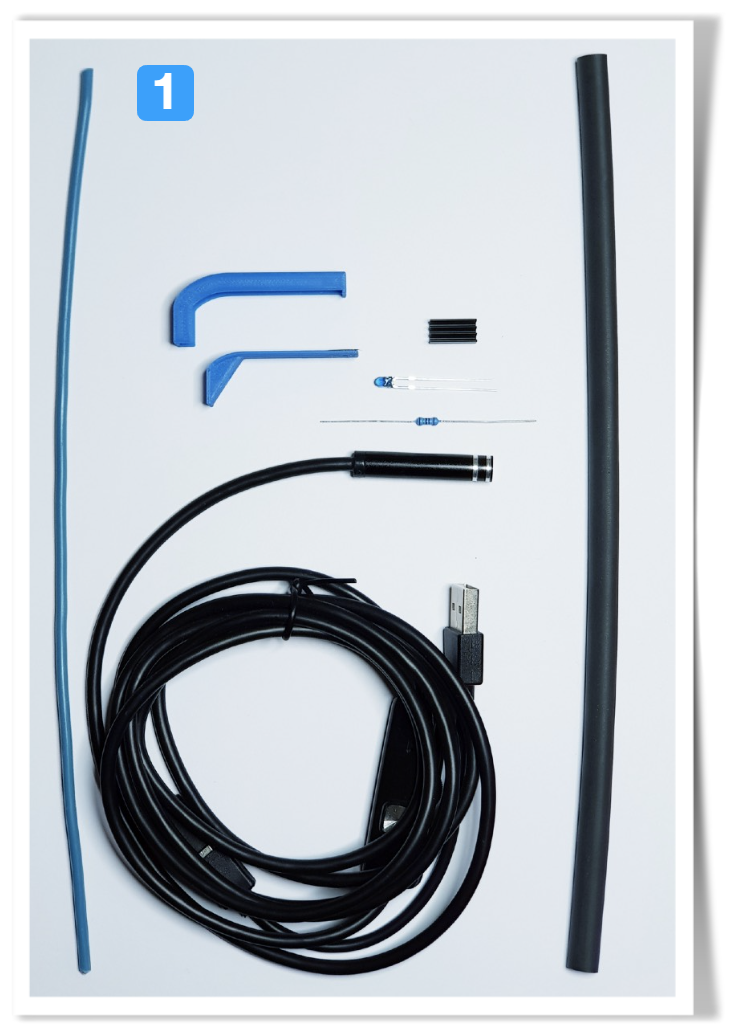
The simple version of the eyetracker just uses the endoscopic camera and attaches it to the frame of the safety goggles - no soldering or 3D-printing required. This can be done in small groups of students (2-3) within 45minutes, once the materials are prepared:
![]()
The copper wire (2.5 mm2) is taken from installation equipment, any hardware store should have a similar selection (here 3 wires are contained, different colors - they don't matter here, since we don't connect any electrical component - it hales saving on the material if we use all of them).
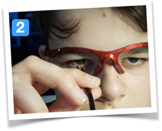
The next step involved a computer to show the live camera feed and find the optimal position of the camera in front of the eye. Since the camera is round, it is also a good idea to mark the top of the camera when the eye is oriented correctly in the camera view - in the picture this is done with a little orange sticker.
Make sure the entire eye is clearly visible, not only the iris. Since cheap cameras have fixed focus, we need to adjust the position sideways (distance to the nose) and the height as well - distance to the eyebrow. For both, we can use the google frame as a reference point:![]()
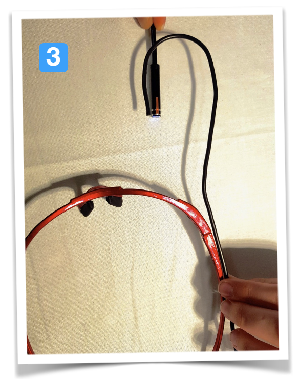
In the 3rd step, we reproduce this position with the flexible wire and bend it, so it will roughly be in the correct position, once the camera is fixed to it. The wire could easily be 30cm long, we cut the excess off at a later stage.
![]()
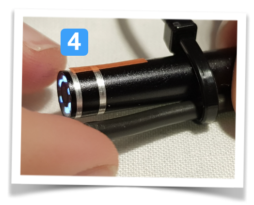
Now it is time for cable-ties - use two of them to fix the camera with the marking at the top to the wire - do not fully tighten it now!
![]()
Then fix the flexible cable together with the USB cable to the frame. Leave the cable-ties as they are - once tested, they will be fixed and cut.
![]()
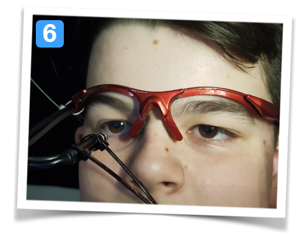
Now ask the pupils to put on the safety frame with the camera attached and pay attention to the cable-ties and the eyes ;-)
This is the step to check for proper alignment and move the camera by bending the wire. Small adjustments can be done later at any time, but we need to get the rough orientation and dimensions right. Use the computer to check the camera feedback...![]()
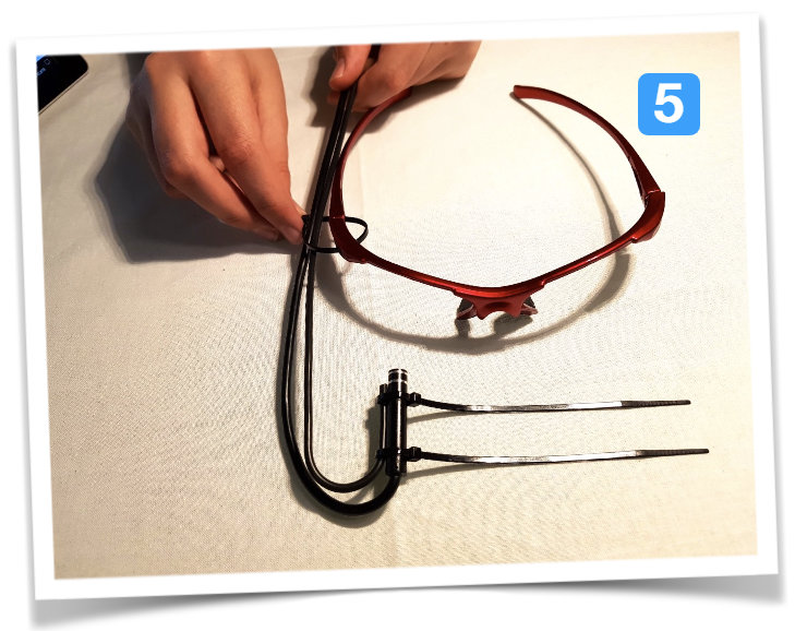
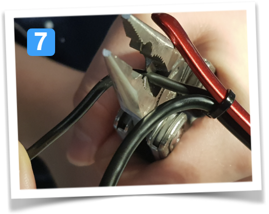
Once everything looks good it is time to tighten the zip-ties using pliers and cut the excess of the flexible copper cable (acting as a support). If you are working with groups of students, make sure they cut the correct cable - not the USB one ;-)
![]()
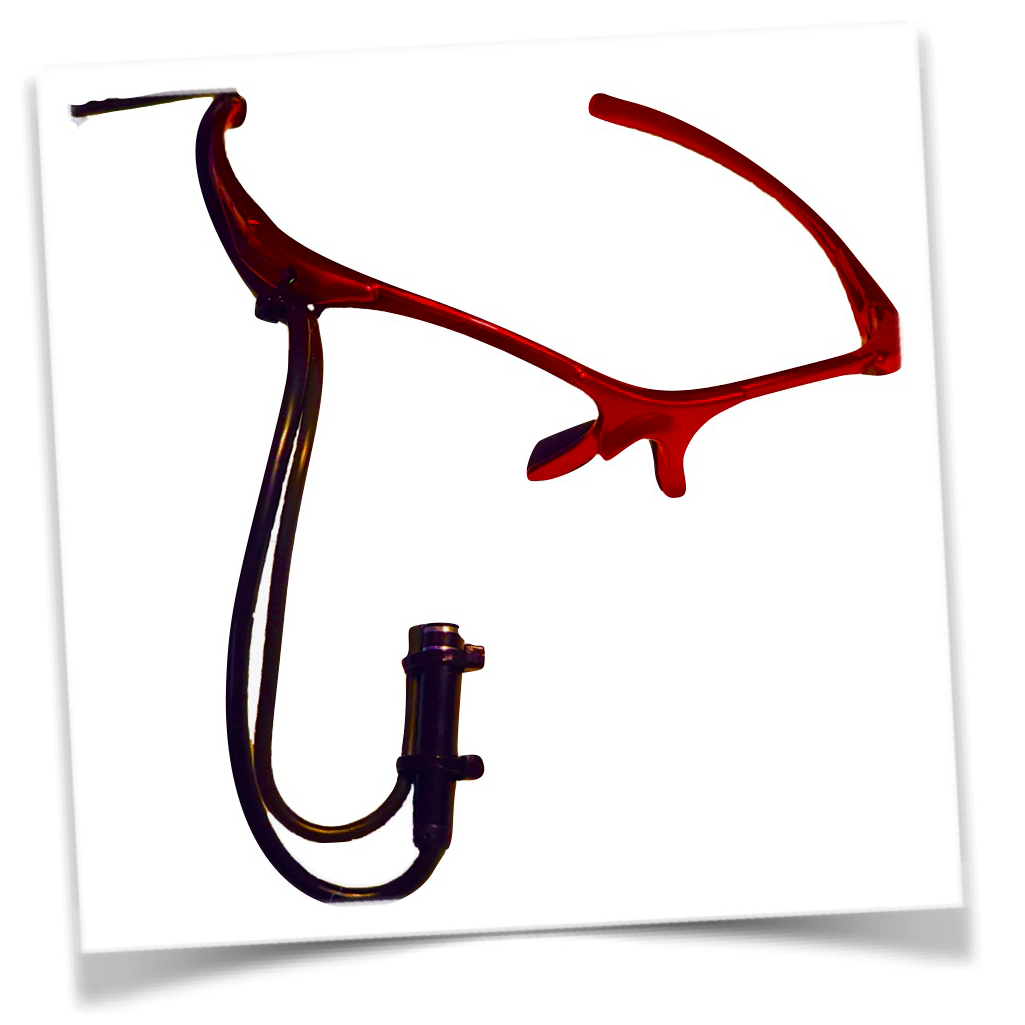
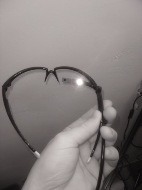
And this is the result - a simple construction suitable for primary school projects using an endoscope camera and a safety goggles frame with some support by a copper wire:
![]()
-
2Using the Eyetracker (simple version) - blockbased coding like Scratch3
Scratch is a graphical programming language that is ideal for starting with young students, especially in primary school and early secondary school. The programming language is being developed by MIT and will be released in its third version (Scratch 3) at the beginning of 2019. Additional functions can be implemented via extensions, e.g. for processing voice commands or images.
The robotics manufacturer Makeblock offers a programming environment based on Scratch3, into which machine vision can be integrated very easily. The software can be installed free of charge at the following link:
https://www.makeblock.com/software/mblock5
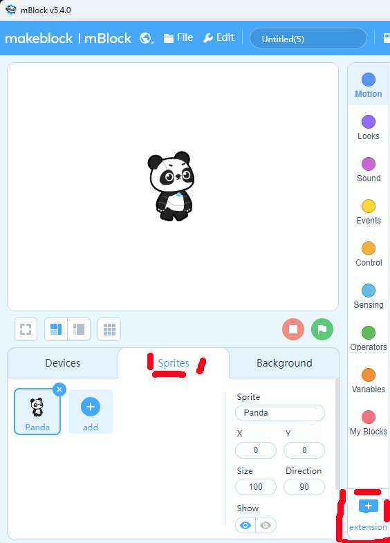
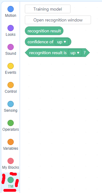
Then add the extension for training neural networks ("Teachable Machine") - use the Sprites part of the coding area:
![]()
![]()
This will add image categorization into your sprite coding categories:
![]()
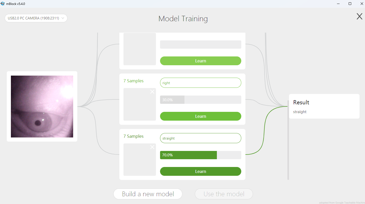
By default, Teachable Machine offers 3 categories. You add images from a webcam to each category for learning. While you can always add more pictures, the number of categories cannot be changed later, unless a completely new model is built. To differentiate for age groups or to allow students to progress at their own pace (scaffolding) you could also start with just 3 categories - have a robot driving straight on and only change left/right turns by eye movements.
For a full directional control we need the 4 direction categories "up", "down", "left" and "right" - and also a category where the eye just looks straight on. Otherwise you "force" the model to always decide for one direction, even if the wearer of the eyetracker does not indicate a direction at all...
With the images being added, the model is built immediately incorporating them and getting precise with more pictures; 15-30 per category are a good indication. Once the file is saved, closed and opened again, you will no longer see the images - they are not kept, only the model generated from them. This all happens locally, no cloud-based image processing is taking place (GDPR-"safe" for schools).
![]()
If the advanced eye tracker is mounted on the right side, the image of the camera is rotated by 180° as seen in the figure above. Here this does not matter, because the training algorithm processes the images themselves, regardless of the position of the eye. For the evaluation with Python and openCV, the image can simply be rotated.
To control the robot, use messages between sprites and the robot programming area:
![]()
In scratch programming, only a section is shown because the structure is repeated:
![]()
If a direction is recognized, an arrow in the corresponding direction is shown as a sprite (costume). This gives the user visual feedback as to which direction of movement has been detected. If the space bar is then pressed while a direction is detected, the information about the direction of gaze is broadcast to other parts of the program - e.g. for the direction of travel of a robot. If the user is looking straight ahead, nothing is displayed and a stop command is transmitted. We need a confirmation of the direction because the gaze also moves unintendedly and the space bar on the keyboard is the biggest button and easy to hit ;-)
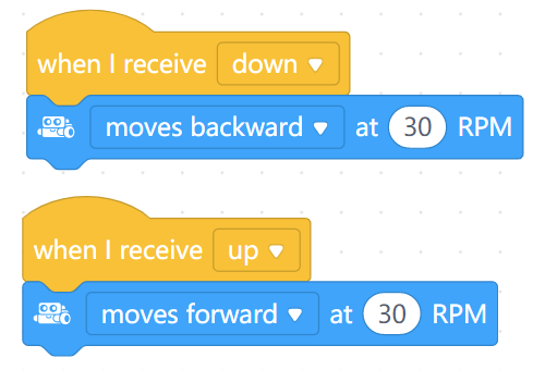
It takes a bit of practise to intentionally move one eye into the desired direction while also checking the arrow on the screen for the visual feedback (ideally use peripheric vision). So for students or young pupils, it might be easiest to start with left/right commands only...The robot-part of the code just receives the broadcasts and executed different driving commands:
![]()
Again, this picture only shows a section of the code... the example file has code for 3 different robots...
-
3Advanced version - IR illumination and own camera case
If you like, you can build an advanced version of the eyetracker. Professional eyetracker illuminates the eye with IR light and checks for reflection on the iris or takes the darkest spot (iris) - depending on the position of the tracker.
BE CAREFUL WITH IR ILLUMINATION. We cannot detect IR light and if too strong, it could cause damage to the retina. Only use extremely low-power LEDs and increase the resistor so that the LED just emits enough light.
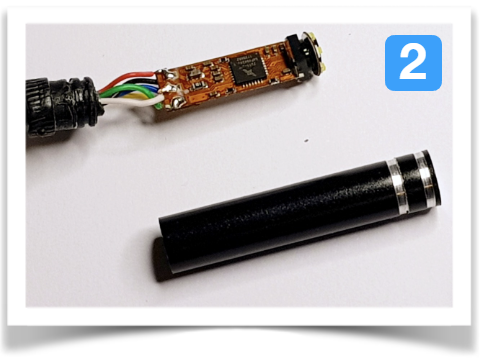
This is the overview of materials needed: a 3mm IR LED with a resistor, support wire a small heatsink (ideally), and a shrinking tube.
![]()
Using pliers, carefully remove the cylindrical housing of the endoscope camera. The camera module rests vertically on the circuit board at the front:
![]()
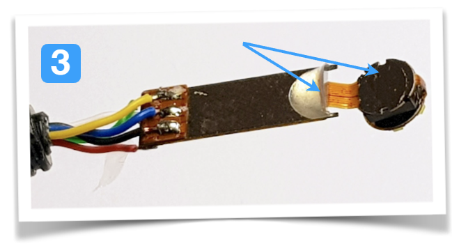
Carefully detach the small camera module from the circuit board (hot glue holds it in place). Do not damage the thin conductor tracks. For installation in the 3D-printed housing, the hotglue drop must be removed with a cutter. There is a tiny circular circuit board on the camera module with the white LEDs for illumination (fracking away from the observer in the picture) - please remove this and cut the conductive tracks.
![]()
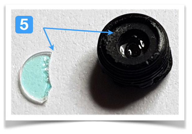
Unscrew the lens from the camera module - the IR cut filter has a reddish shimmer. We need to remove this filer, it blocks nearly all IR light:
![]()
Using a cutter, carefully remove the IR cut filter but leave the lens intact ;-)
![]()
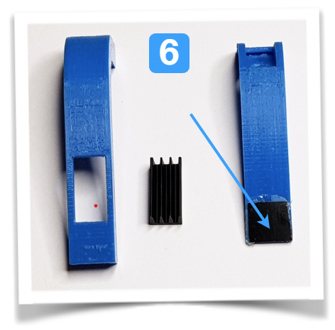
Create a 3D housing and print it, and adjust the cut-out for the heat sink if necessary (the PCB has a silver surface that gets quite warm. To be on the safe side, it should be dissipated by a heat sink). Stick a piece of exposed film onto the camera opening of the 3D-printed lid.
Since there are many different endoscopic cameras, any 3d-files provided would probably not match... Since this is a school project, the students could easily creat the housing themselves :-)
![]()
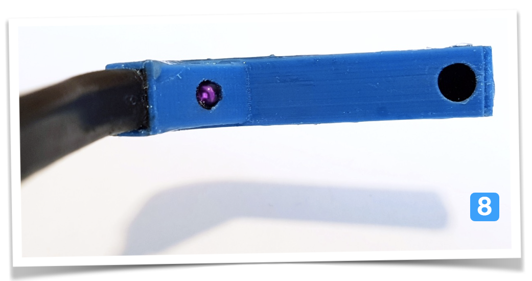
Glue the IR-LED into the lid, and connect the terminals of the LED with the cables powering the previous camera light - in my example, they were blue = cathode, yellow = anode. They can be desoldered from the circuit board and only be used for the IR LED with a resistor.
Then glue everything in the housing. Next to the connection cable, glue in a wire for stabilization:![]()
This is the closed 3d-printed case for the eyetracker. The supporting wire and USB-cable are enclosed in a heat-shrinking tube. The IR-LED is on, barely visible to a normal smartphone camera. The endoscopic camera is covered by exposed analog film, acting as a blocking filter for visible light, but letting IR pass.
![]()
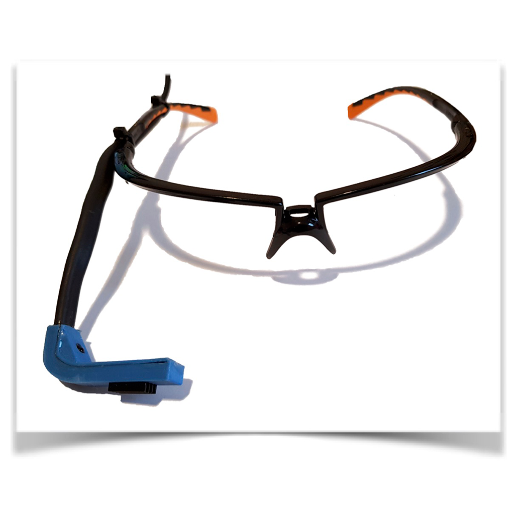
This is the finalized version of the eyetracker:
![]()
If you check the IR illumination with a IR camera, you can see that even low-power LEDs emit quite a powerful light beam:
![]()
-
4Eyetracking in openCV/Python
In Python, you can address the camera like any video device. Further processing of the image data is then already possible with a few lines of code... here is an example to find the pupil:
# -*- coding: utf-

# import openCV
import cv2
#is not used in the example, but makes sense for further experiments...
import numpy as np

# use first video device (USB); if there are several cameras, select the correct number.
cap = cv2.VideoCapture(3)

while True:

    video = False # wait for frame from USB device
    while video == False:
        video, frame = cap.read() # keep reading until we get a frame

    # now we can search for the pupil... there are different ways to do it
    # 2 examples:   use binary conversation, check for black spot (iris)
    #               search for circular structures of the right size

    #flip retrieves frame, it is rotated 180°
    (h, w) = frame.shape[:2]
    center = (w / 2, h / 2)
    M = cv2.getRotationMatrix2D(center, 180, 1.0)
    frame = cv2.warpAffine(frame, M, (w, h))

    #convert to grayscale
    gray = cv2.cvtColor(frame,cv2.COLOR_RGB2GRAY)

    #apply a gaussian filter, removing noise
    blur = cv2.medianBlur(gray, 5)

    #apply adaptive bightness correction
    cl1 = cv2.createCLAHE(clipLimit=2.0, tileGridSize=(3,3))
    clahe = cl1.apply(blur)

    # find iris by black/white conversion --> only exmaple image, no further processing
    (thresh, iris) = cv2.threshold(clahe, 50, 255, cv2.THRESH_BINARY)

    #find circular structures with radi between 10 and 30
    circles = cv2.HoughCircles(clahe ,cv2.HOUGH_GRADIENT,1,20,param1=50,param2=30,minRadius=10,maxRadius=40)

    #only check if any circles have been found
    if circles is not None:
        circles = np.round(circles[0, :]).astype("int") #convert float to integer
        print ('integer',circles) #print the radi for adjustment
        # mark all circular structures in the received frame
        for (x,y,r) in circles:
            cv2.circle(frame, (x, y), r, (0, 0, 255), 2)

    cv2.imshow('Frame', frame) #retieved original image with circules marked
    cv2.imshow('Auge', iris) #show black and white conversion; iris=black spot
    cv2.imshow('Clahe', clahe) #
    if cv2.waitKey(1) & 0xFF == ord('q'):
        break
This will show 3 images - the original frame received from the camera with circular structures marked, the grayscale conversion with locally adjusted brightness and a black/white image with the only black spot moving to be the iris.
It is an example of two different approaches (black/white conversion and searching for circular structures). The found coordinates from the second approach are printed in the console, so students could process them further.
20€ DIY-Eyetracker for school projects
Build an inexpensive eyetracker with primary school students - and control real world robots with block-based coding!


Discussions
Become a Hackaday.io Member
Create an account to leave a comment. Already have an account? Log In.
[this comment has been deleted]
The project your teacher asked you to do? I hope the explanations here are pretty straight forward for you to rebuild your own version. Maybe consult your teacher if you are unsure what to do. Let me know if there is anything I can help with...
Are you sure? yes | no
[this comment has been deleted]
This is about building a device that can track your eyes so you can use this as an input to a computer system.
Are you sure? yes | no
[this comment has been deleted]
?
Are you sure? yes | no
A student is unlikely to do this.
Are you sure? yes | no
I did a workshop with the simpler version of this eyetracker with a 3rd class (pupils aged 9-10 years old, they had first coding lessons in school already in class2).
So, it is not unlikely, it depends on the educators/mentors and students' engagement...
Are you sure? yes | no