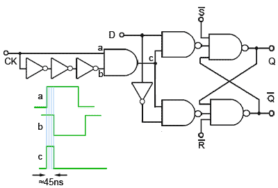
in the summer of 2016 I needed to tackle sequential circuits. So started the real fun ( hair pulling ). On a single flip-flop level I started with the basic R-S to J-K to the D. However when I tried to make these circuits toggle then I began to understand the problems of signal levels, timing and edge vs. level triggering. No matter how many searches on the internet I did, I could not get things to toggle or at least toggle without random errors. I had built a clock using transistors but was not sure of the signal purity ( The only test equipment I have is a analog vom and a transistor tester ). I made the call to allow one chip for this project and that is a trusted 555 timer chip. Did that help, No way. Finally I came across a circuit that converts the square wave output of my clock to a very short pulse. Now my flip-flops started to toggle the way I wanted.

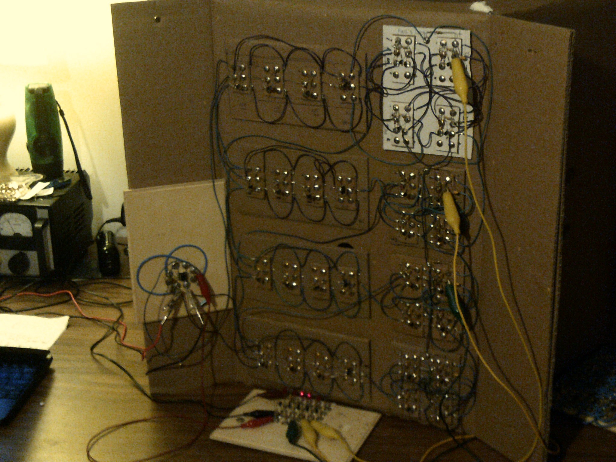
Below is my program counter connected directly to the clock board on the left. There are four toggle D flip-flops on the right and note the pulser boards to the left of each one. Without them I would not have any hair left.
 Dr. Cockroach
Discussions
Become a Hackaday.io Member
Create an account to leave a comment. Already have an account? Log In.
I don't recommend this kind of "pulse generator", at least for a potentially complex synchronous system. A master-slave flip-flop is "safer" as long as the clock signal is nicely square and propagates correctly everywhere.
I managed to hack a 10-transistors synchronous D flip-flop (not latch): https://hackaday.io/project/9376-yet-another-discrete-clock/log/34817-even-better-10tff However it works with MOSFET, not bipolar transistors. I still search a method to adapt this topology to bipolar, I might have something but it's for ECL, not DTL levels...
Anyway, you can create a suitable edge detector with a RC circuit, no need of a series of inverters (RC is more flexible and you can tune the pulse width with a potentiometer).
Note : many designs used transparent latches controlled by a 4-phase clock.
Are you sure? yes | no
You can make a true edge-triggered D-flop from six single-transistor inverters and a bunch of diodes, too. Diode-OR gates combined with the inverters makes NOR gates, which are easily fastened into an edge-triggered flop. The flop triggers on the falling edge of the clock, which is different from the typical 7474-type flops, but you can easily work around that. I made one with diode inverters, described here:
https://hackaday.io/project/11677/log/37976-ddl01-hex-nor-gate
Scroll down to the d-flop section, then just replace the diode (DDL) NOR gates with DTL NOR's, and you're all set :-)
The D-flops toggle if you feed the Qbar signal back to the D input.
Are you sure? yes | no
Yay thanks ! I was looking for this circuit/schematic :-)
Are you sure? yes | no