 Dr. Cockroach
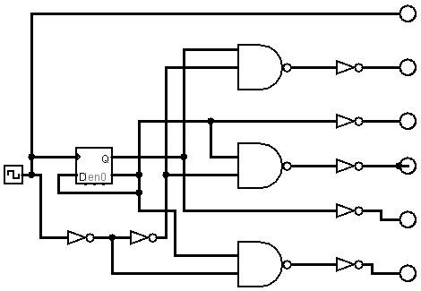
I needed to start looking into the FSM part of this project and found a circuit that outputs 5 pulses for every 2 clock pulses ( I cant remember who posted this but if your out there reading then please chime in ). This should help head off any problems with propagation delays along the chain of command. A J-K toggle flip-flop is used to input to the sequencer. ( by the way, I do now have Logisim and Qucs as simulators on my notebook so I can check out the circuits ahead of time. The J-K on the left using nor gates and sequencer on the right using nand gates.
I had a senior moment - The link for the FSM sequencer circuit is Rory Mangles and his TinyTim at http://www.northdownfarm.co.uk/rory/tim/

Discussions
Become a Hackaday.io Member
Create an account to leave a comment. Already have an account? Log In.
You should take a look at logisim-evolution (https://github.com/reds-heig/logisim-evolution) as well.
Additionally, Falstad's circuit simulator (http://www.falstad.com/circuit/) might also be useful if you want to tinker on a circuit at the component level instead of logic gates.
Are you sure? yes | no
Wow...
I can't "read" the wires, could you show a schematic view ?
Are you sure? yes | no
Hi there, I added the Logisim layout. Only diff is I used a J-k for real
Are you sure? yes | no
thanks ! this "speaks" to me better :-)
Are you sure? yes | no