 Dr. Cockroach
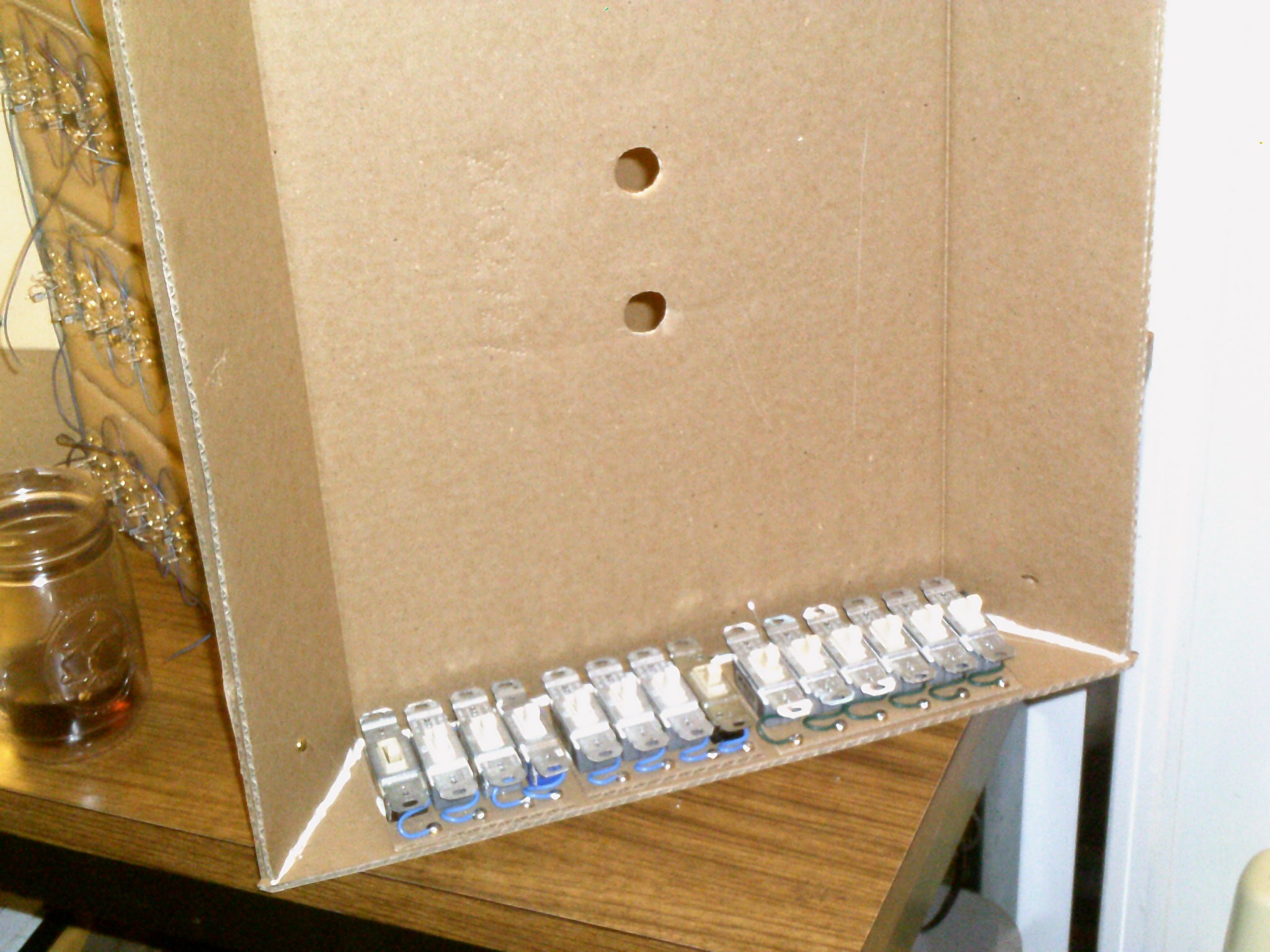
Well, I have started the layout for the switch input section for this machine. As with my 4-bit adder, I am using household power switches found at the local thrift store. Just a little bit oversized but then again this project is a tad odd anyway :-) The bank of four on the left is address input. The middle bank of four is data input and the right side bank of six is for control functions ( Step, Run, Stop, Reset, Deposit and Examine ).
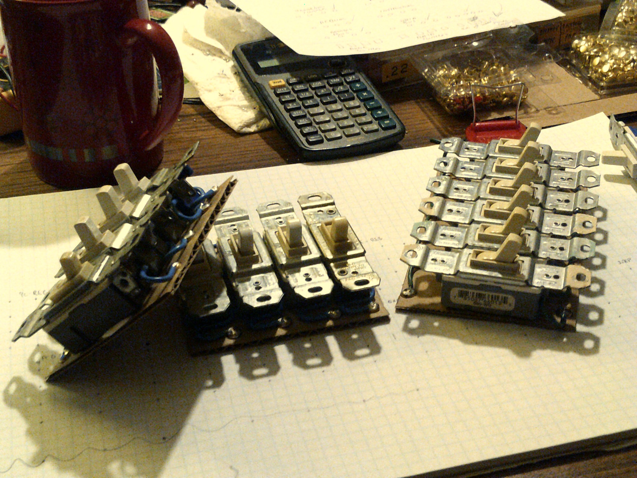
Here is closer look at the switch modules. Again using cardboard as the base material.
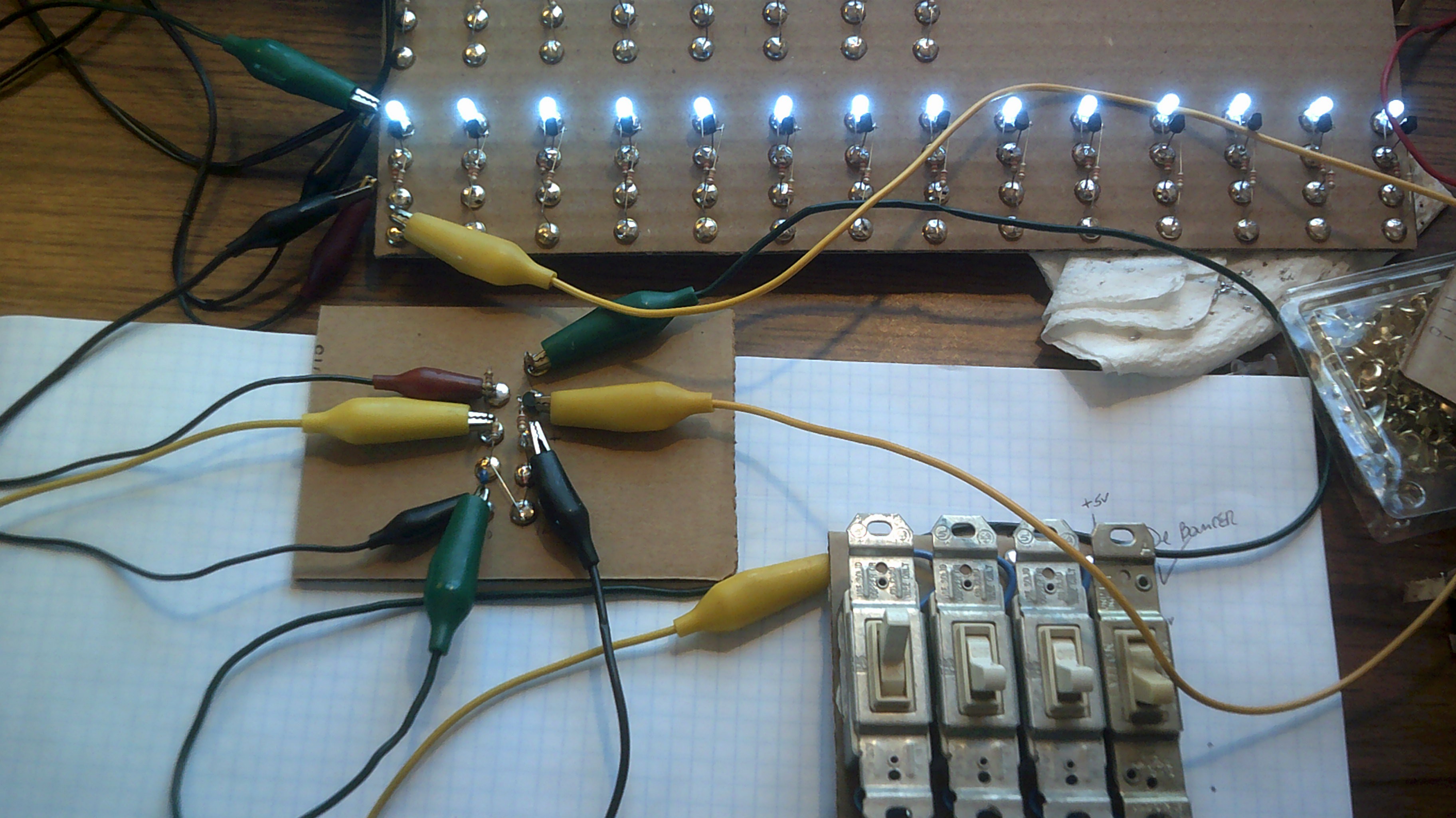
01/09/17 - I have decided on a simple basic RC debounce circuit for the six function switches. So I am laying out a strip with the debouncers and Not gates to be placed between the switches and the lower display led circuits. I am using the Not gates as the led inputs need a solid 0 or 1 to function and the switches are spst and going to ground. I lack a scope to see what my signals look like so my debounce resistor and cap value will be trial and error. Hopefully less error :-) I will post the circuit shortly.
Discussions
Become a Hackaday.io Member
Create an account to leave a comment. Already have an account? Log In.
Now you have me looking around my house at how many light switches we rarely use. I'm wondering if anyone would miss a few :-)
Are you sure? yes | no
seconded.
Are you sure? yes | no
I knew you were!
Are you sure? yes | no
Can't resist a good deal and these switches were only 25 cents each.
Are you sure? yes | no
Hey Mark! Maybe put some switch debouncers on those "switch" modules!
Are you sure? yes | no
I am ahead of you on that , they will be in there :-)
Are you sure? yes | no