Dr. Cockroach
-
August 14, 2017 - Another register
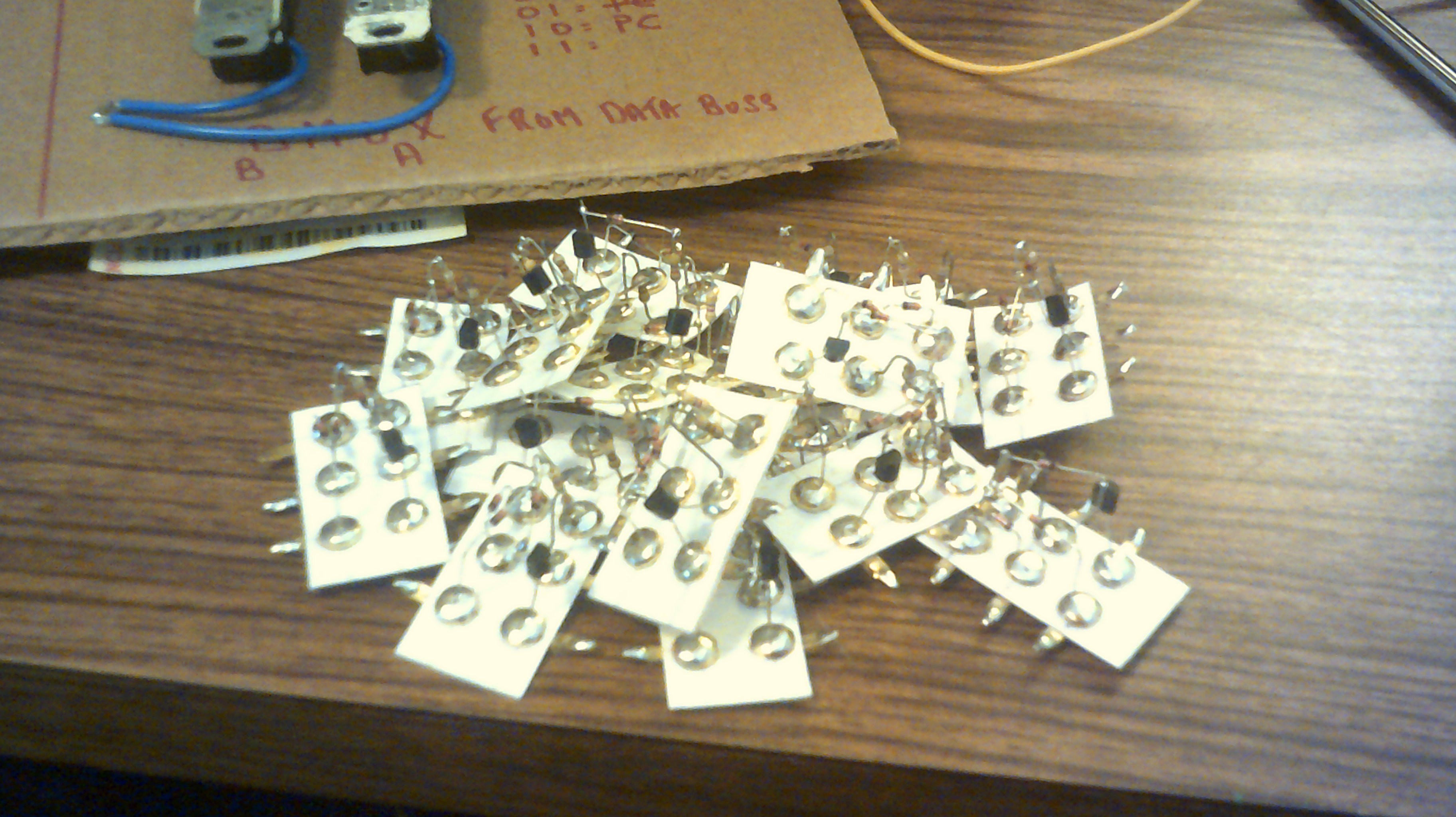
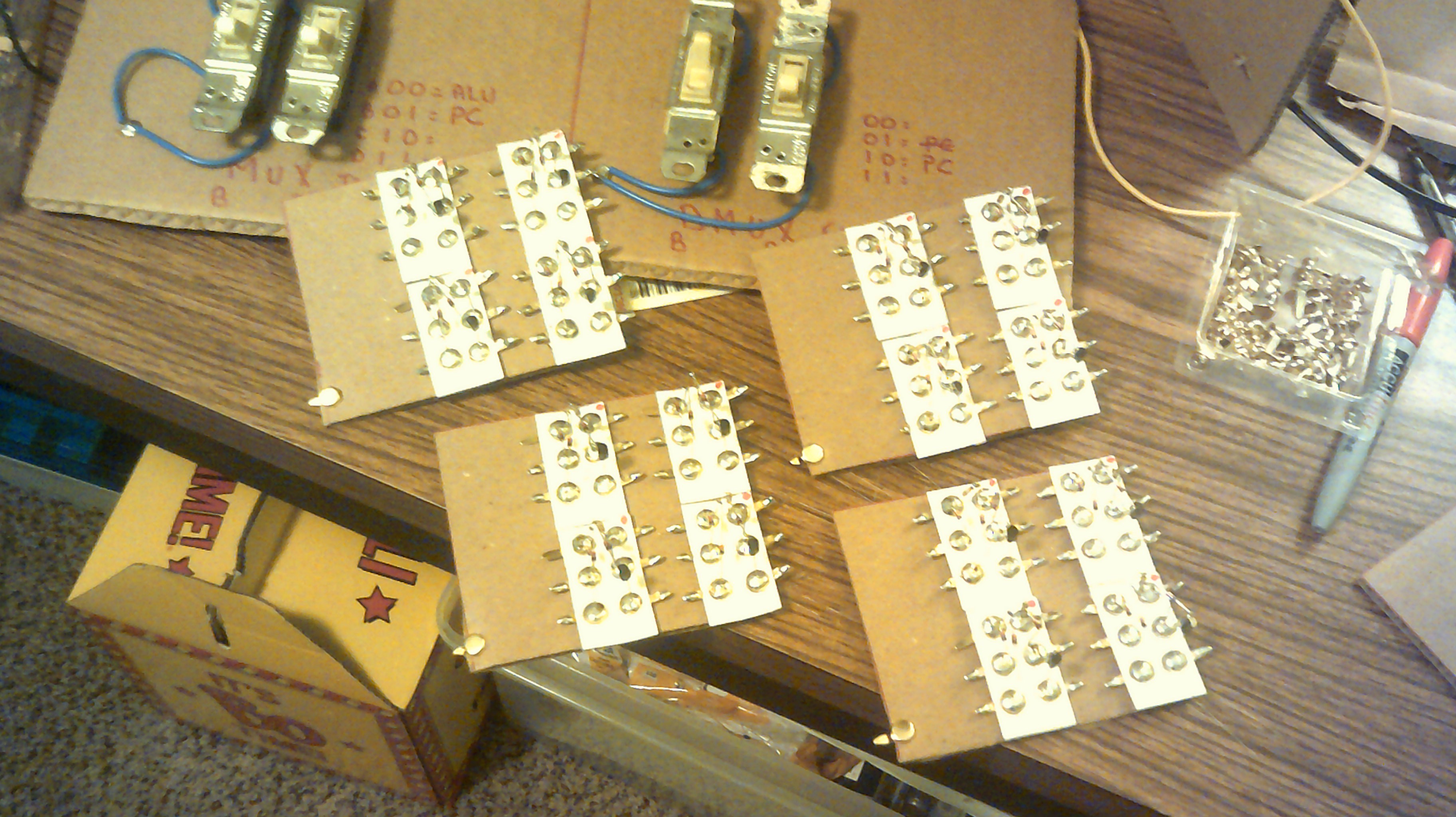
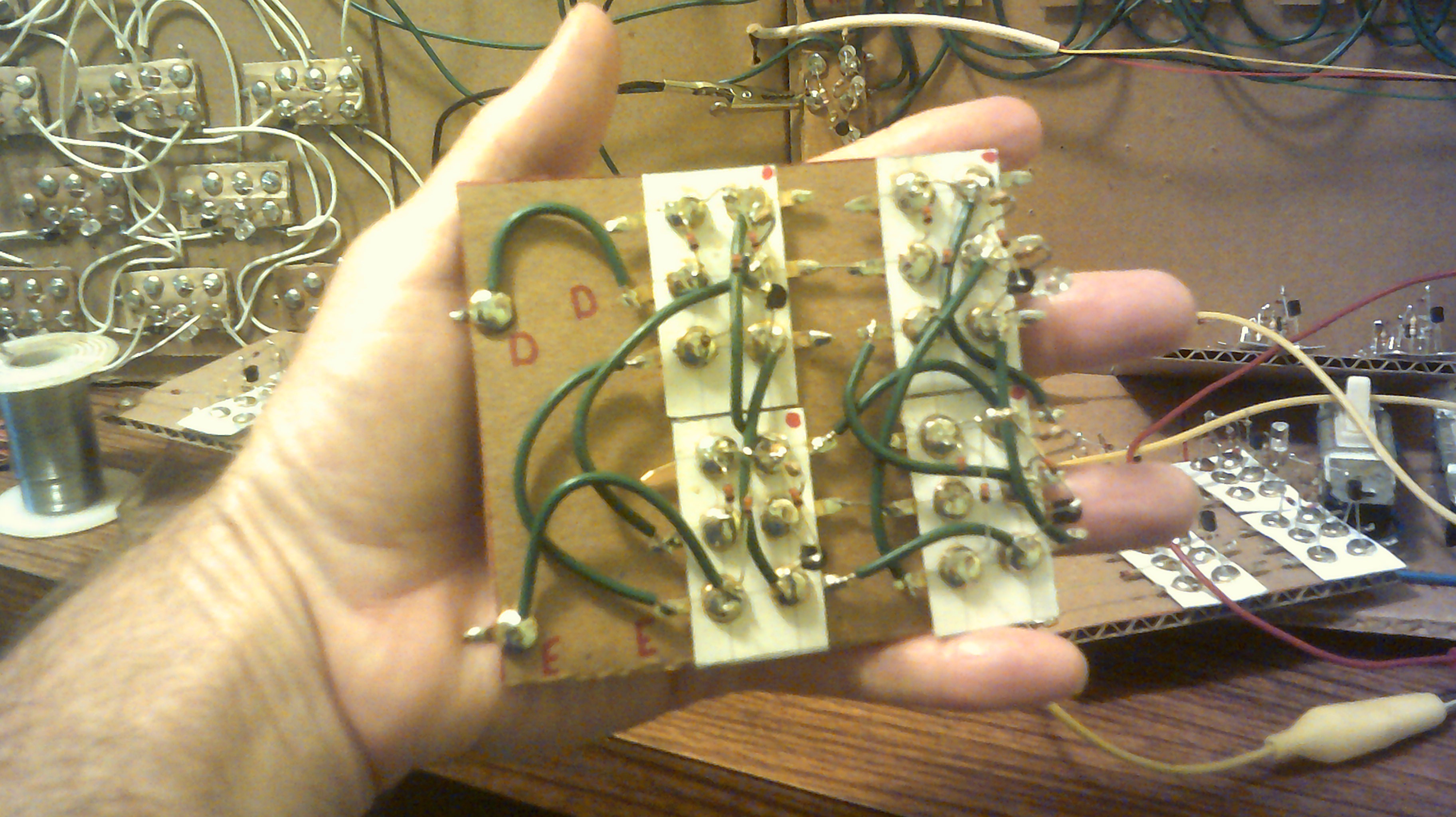
08/14/2017 at 11:36 • 3 commentsAnother register to build, oh what fun. Anyway, this is what I have been up to for the past few days.
![]()
Start off with a pile of Nand gates. Sixteen in this case for a four bit register using D latches.
![]()
The four bare boards.
![]()
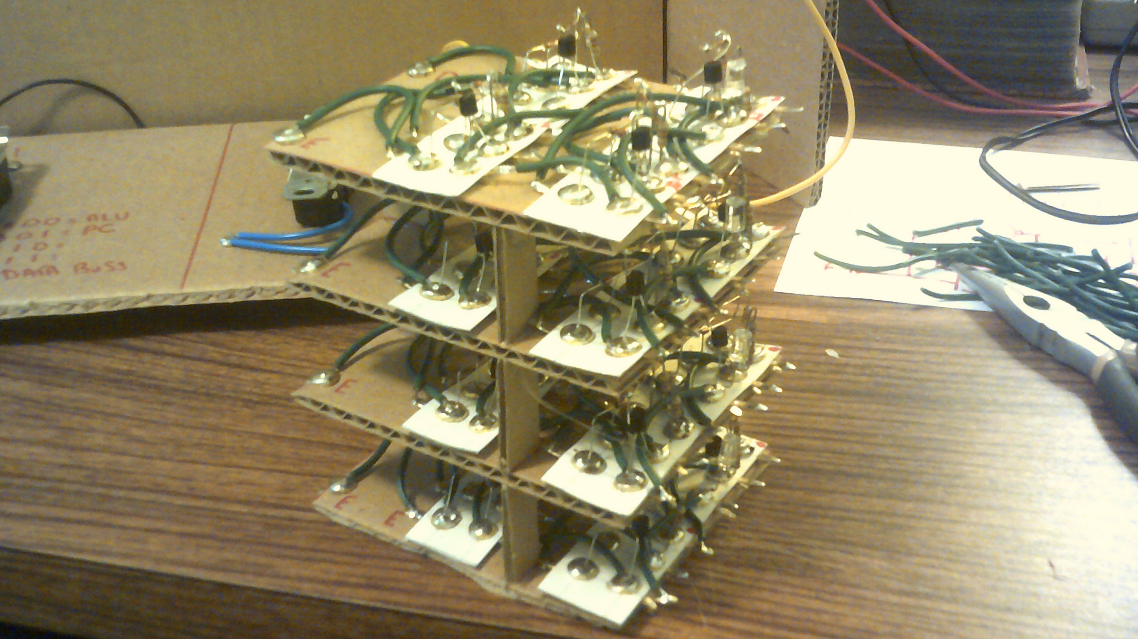
This is one finished and working D latch. Funny how I get it to fit in my hand now but in a chip you would need a microscope to see it :-)
![]()
Now all four bits are finished and I decided to mount them stacked :-)
![]()
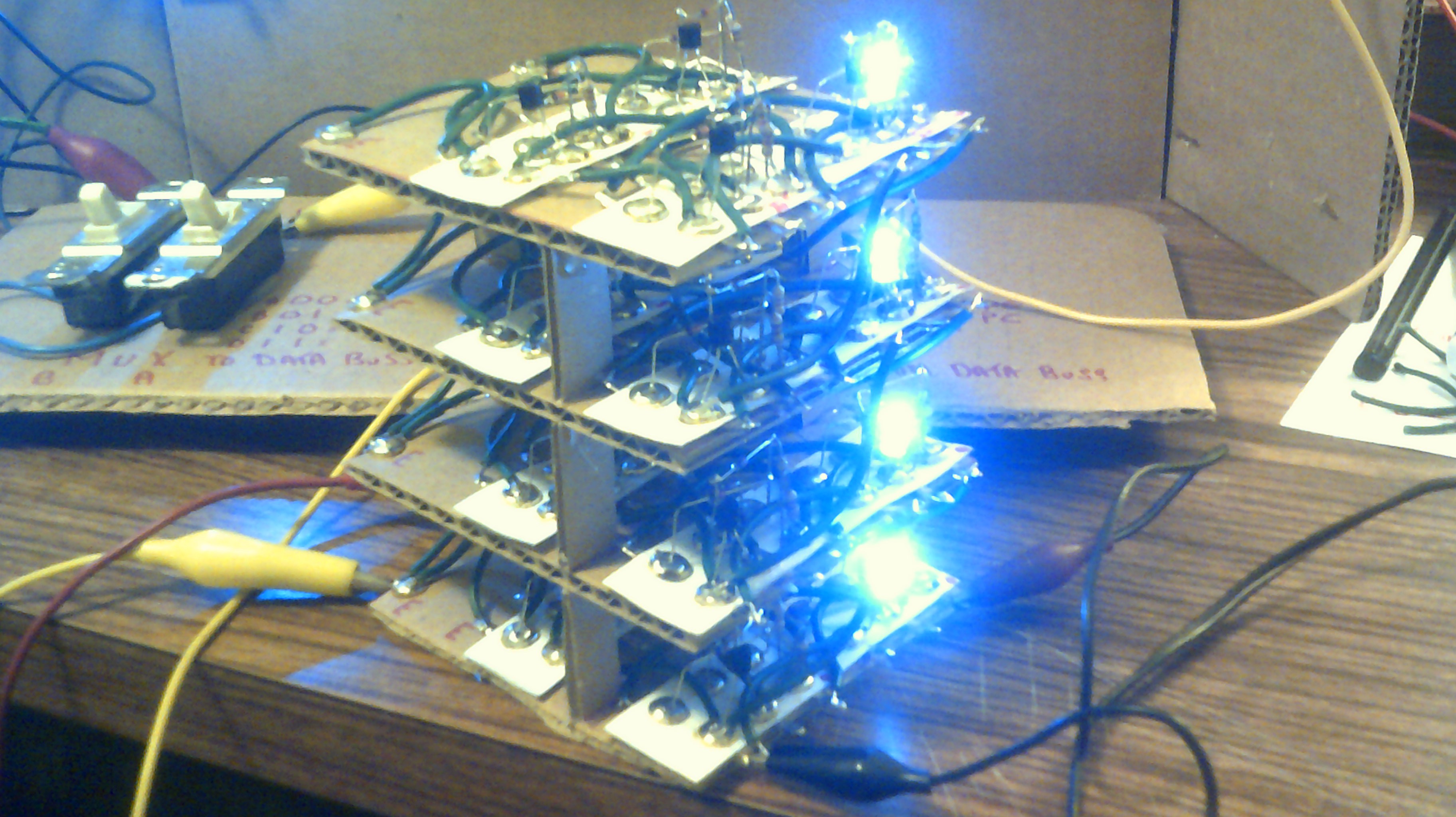
Look Ma, the magic smoke is still inside the parts :-) I did find one open solder connection but not bad for my style of wiring ;-)
-
August 13, 2017 - Antique radio parts need a home
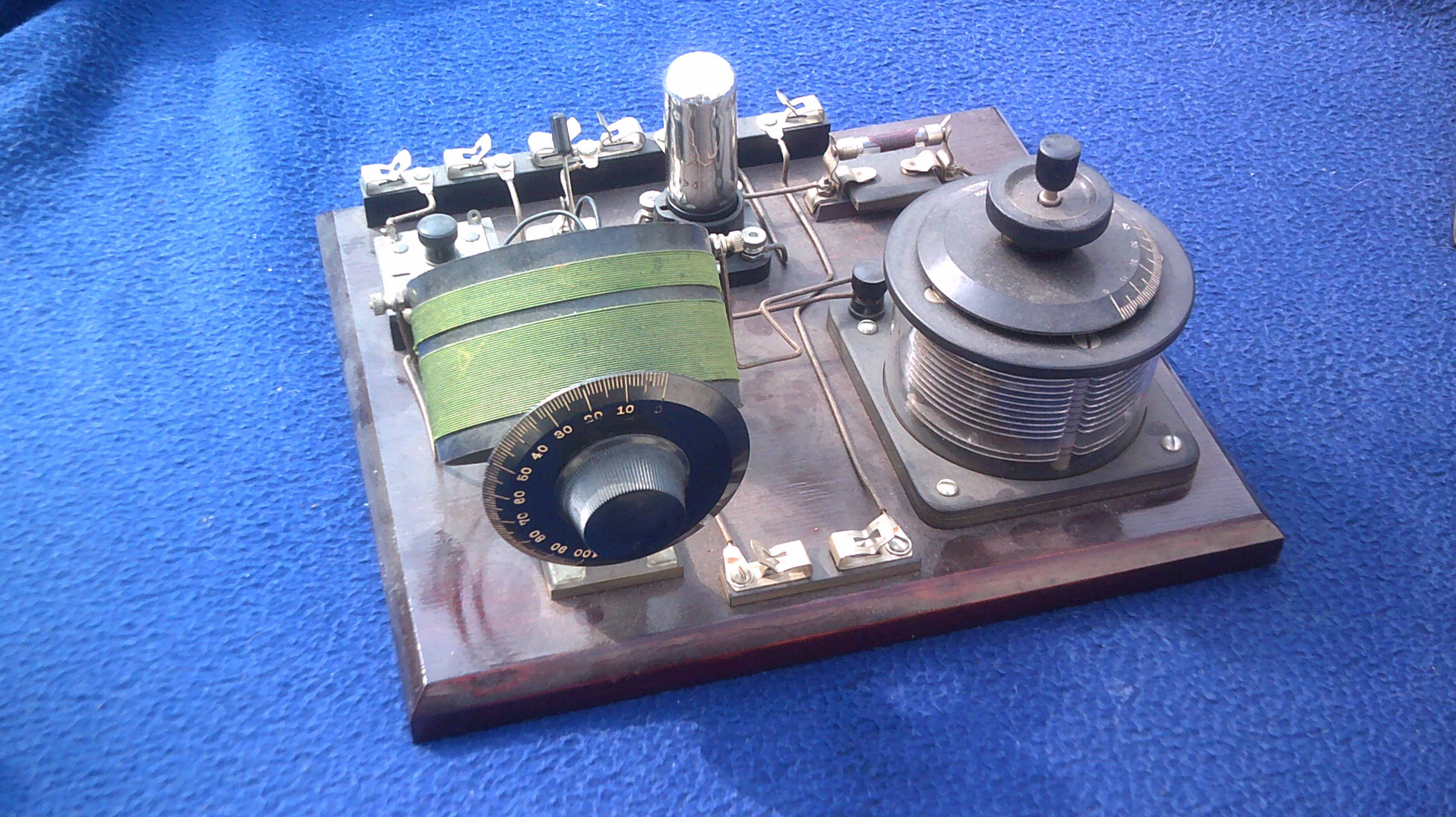
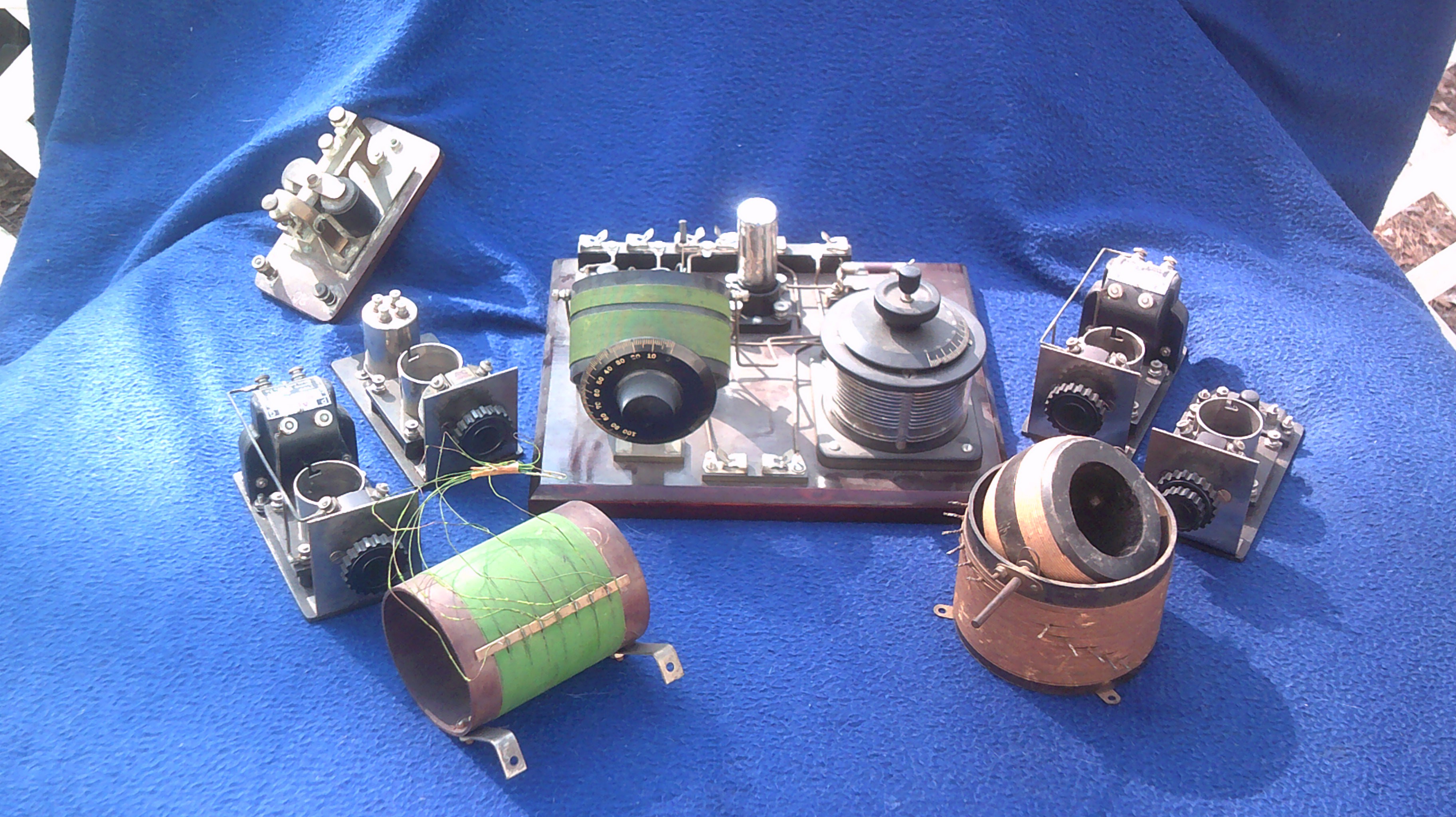
08/13/2017 at 19:21 • 3 comments![]() This is all of whats left of my antique radio collection. These parts need a home and I will give them up for FREE. I have tried contacting the local AWA clubs but no takers. The central radio receiver is a modern build with vintage parts. I would rather not ship so if anyone is visiting the south east NC coast then come on by and the parts are yours :-) I will be in SC for the eclipse on the coast and can have them with me.
This is all of whats left of my antique radio collection. These parts need a home and I will give them up for FREE. I have tried contacting the local AWA clubs but no takers. The central radio receiver is a modern build with vintage parts. I would rather not ship so if anyone is visiting the south east NC coast then come on by and the parts are yours :-) I will be in SC for the eclipse on the coast and can have them with me.![]()
-
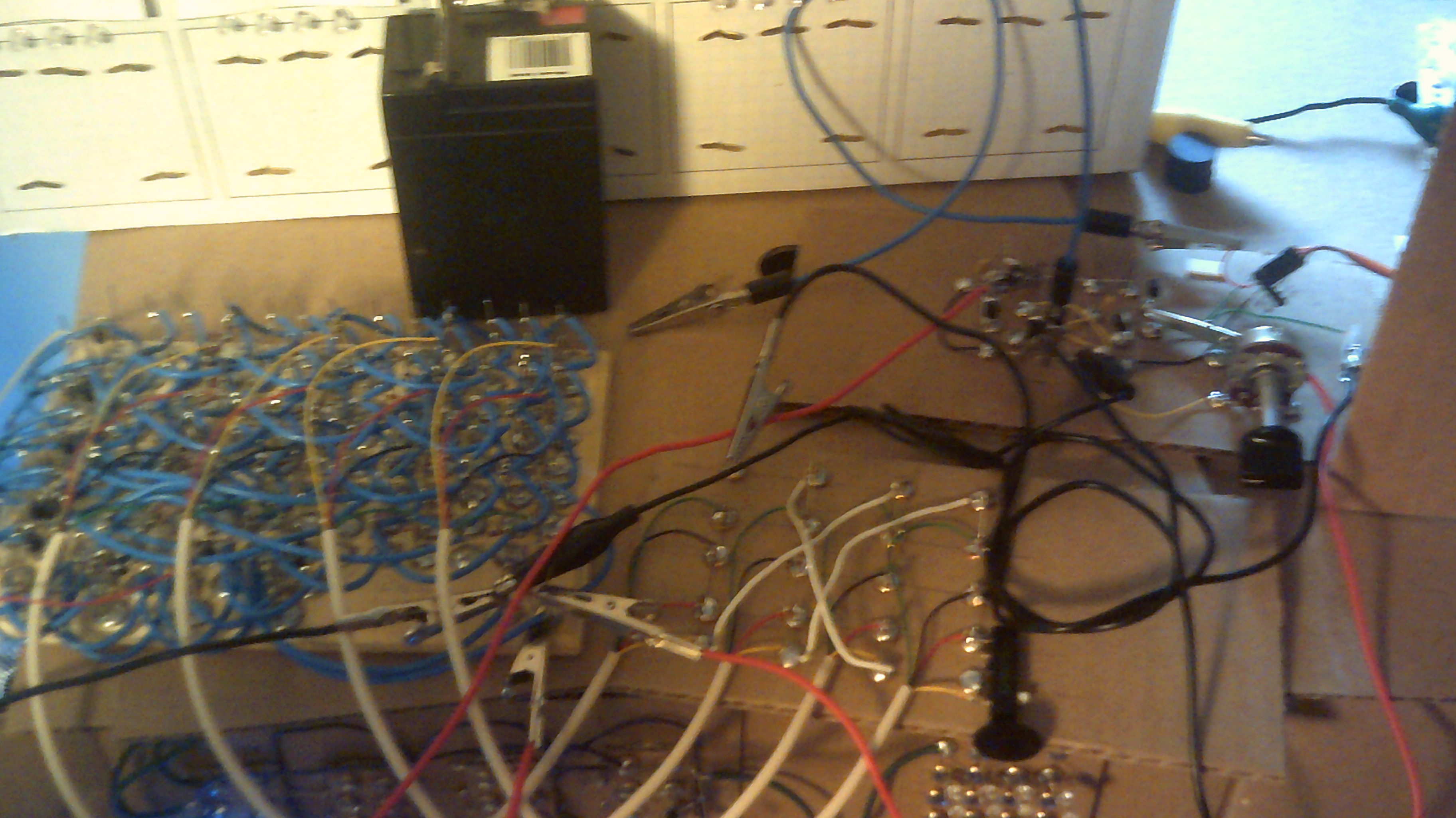
August 7, 2017 - Data is starting to move
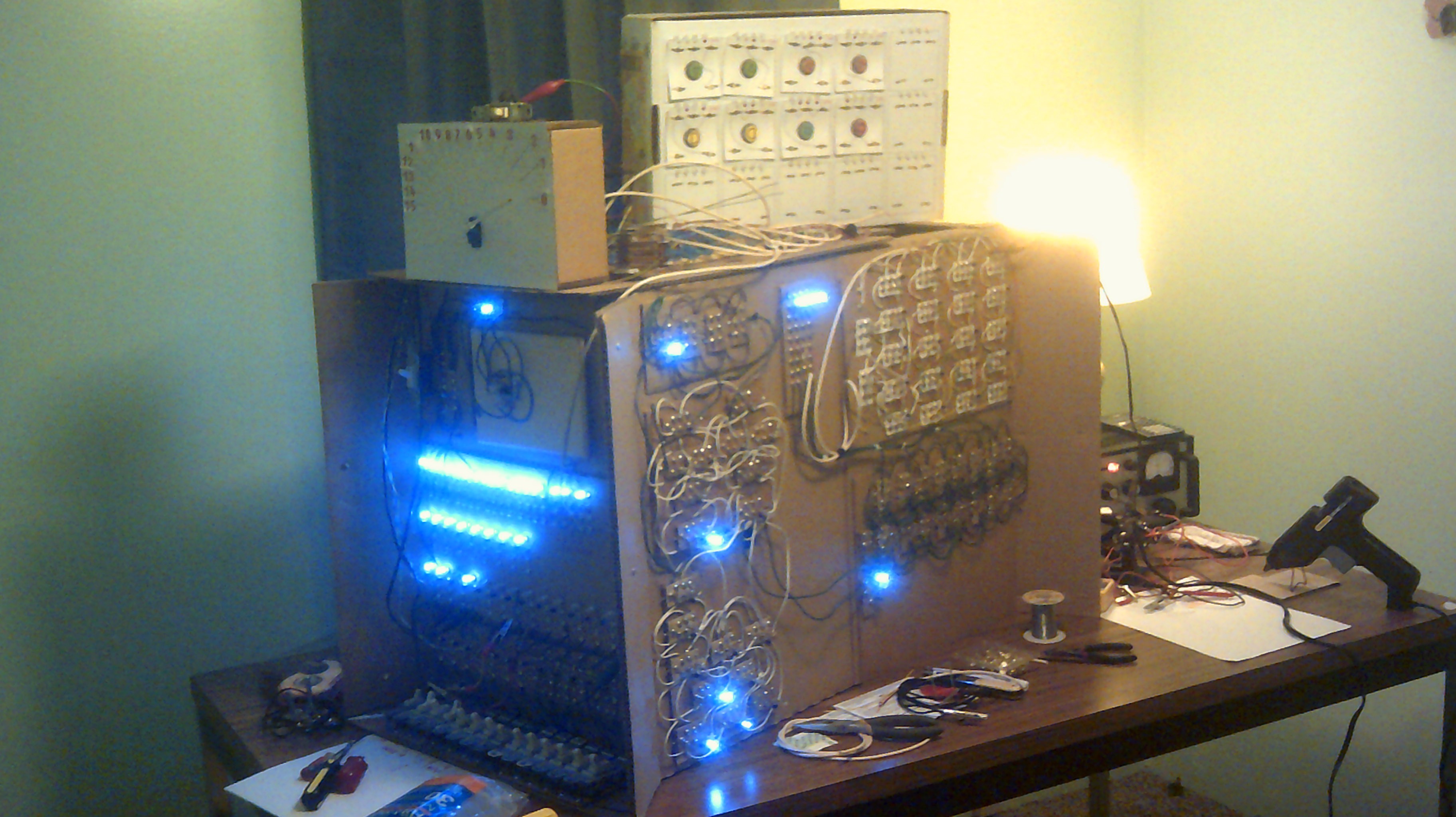
08/08/2017 at 00:25 • 0 commentsI have been thinking a lot about wiring the instruction logic and have started with getting the ALU and PC to work with each other. The MUX and DMUX are working as planned except that the PC out to the MUX needs four additional buffer gates to get the signal level correct. I had the same issue with the ALU some time back and buffers took care of the signal level so will do the same for the PC. The PC register is made up of pnp transistors and was the first register that actually worked for me :-)
A bank of switches is being used to select the active portions of the MUX and DMUX so that with that bank plus the front panel input switches, I should be able to test out what steps are going to be needed for dealing with the instruction logic.
Oh Boy, this is soooooo much fun :-D
![]()
![]()
Just to think that most of the wiring is in my head and not on paper :-O
-
August 7, 2017 - Data is starting to move
08/08/2017 at 00:25 • 0 commentsI have been thinking a lot about wiring the instruction logic and have started with getting the ALU and PC to work with each other. The MUX and DMUX are working as planned except that the PC out to the MUX needs four additional buffer gates to get the signal level correct. I had the same issue with the ALU some time back and buffers took care of the signal level so will do the same for the PC. The PC register is made up of pnp transistors and was the first register that actually worked for me :-)
A bank of switches is being used to select the active portions of the MUX and DMUX so that with that bank plus the front panel input switches, I should be able to test out what steps are going to be needed for dealing with the instruction logic.
Oh Boy, this is soooooo much fun :-D
![]()
![]()
Just to think that most of the wiring is in my head and not on paper :-O
-
July 21, 2017 - It's always something.
07/21/2017 at 23:05 • 0 commentsJust when I think I am on a roll with IO then along comes Murphy Lol. The ALU logic levels for a zero are not what the MUX wants so I am patching in four non-inverting buffers to set things right. The Mux is happier now. Just need to mount the new gates to IO :-)
-
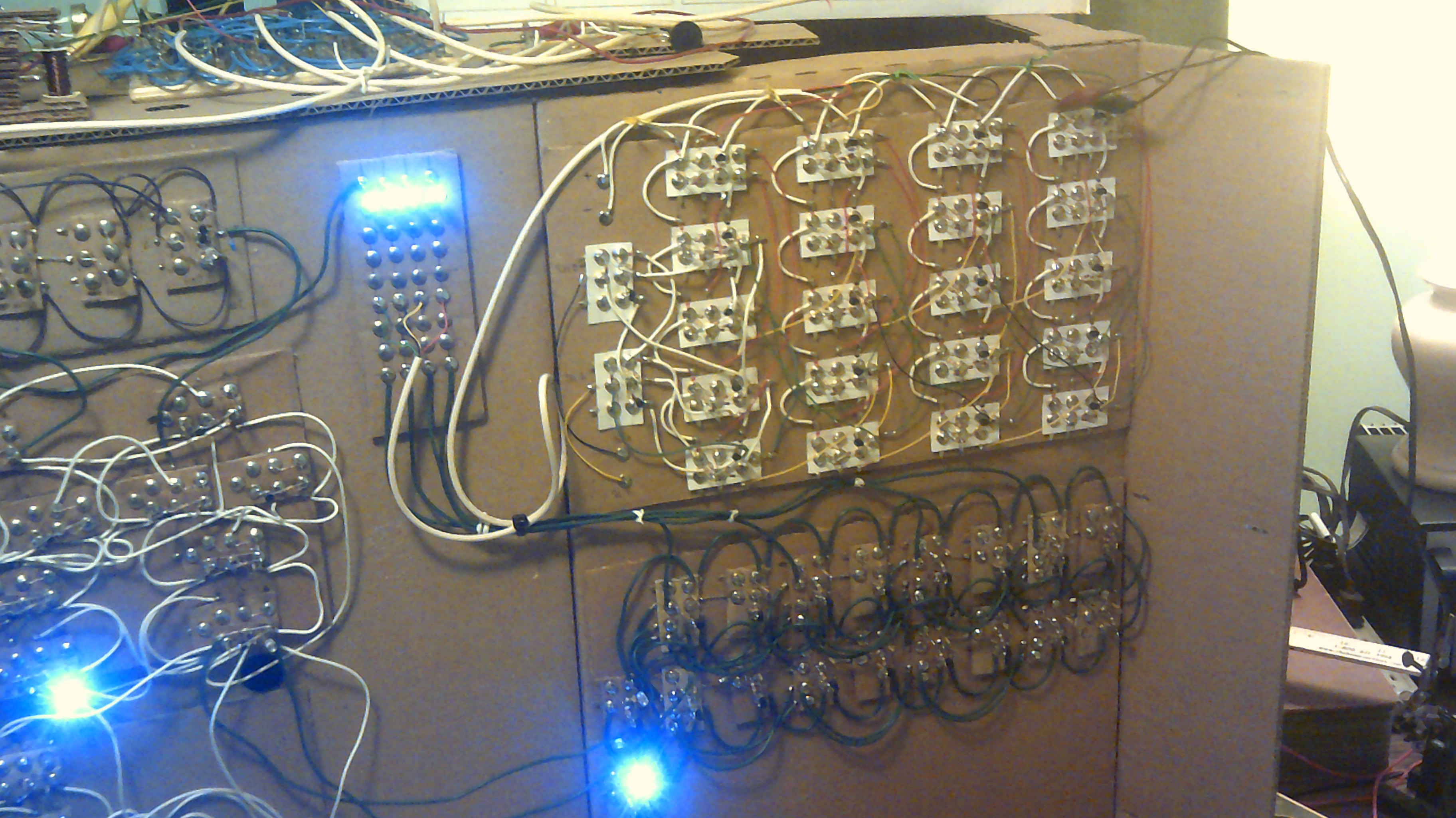
July 16, 2017 - IO is filling up fast
07/17/2017 at 00:13 • 1 commentThe multiplexer is installed and space is filling up.
![]()
![]()
-
July 16, 2017 - MUX here we come
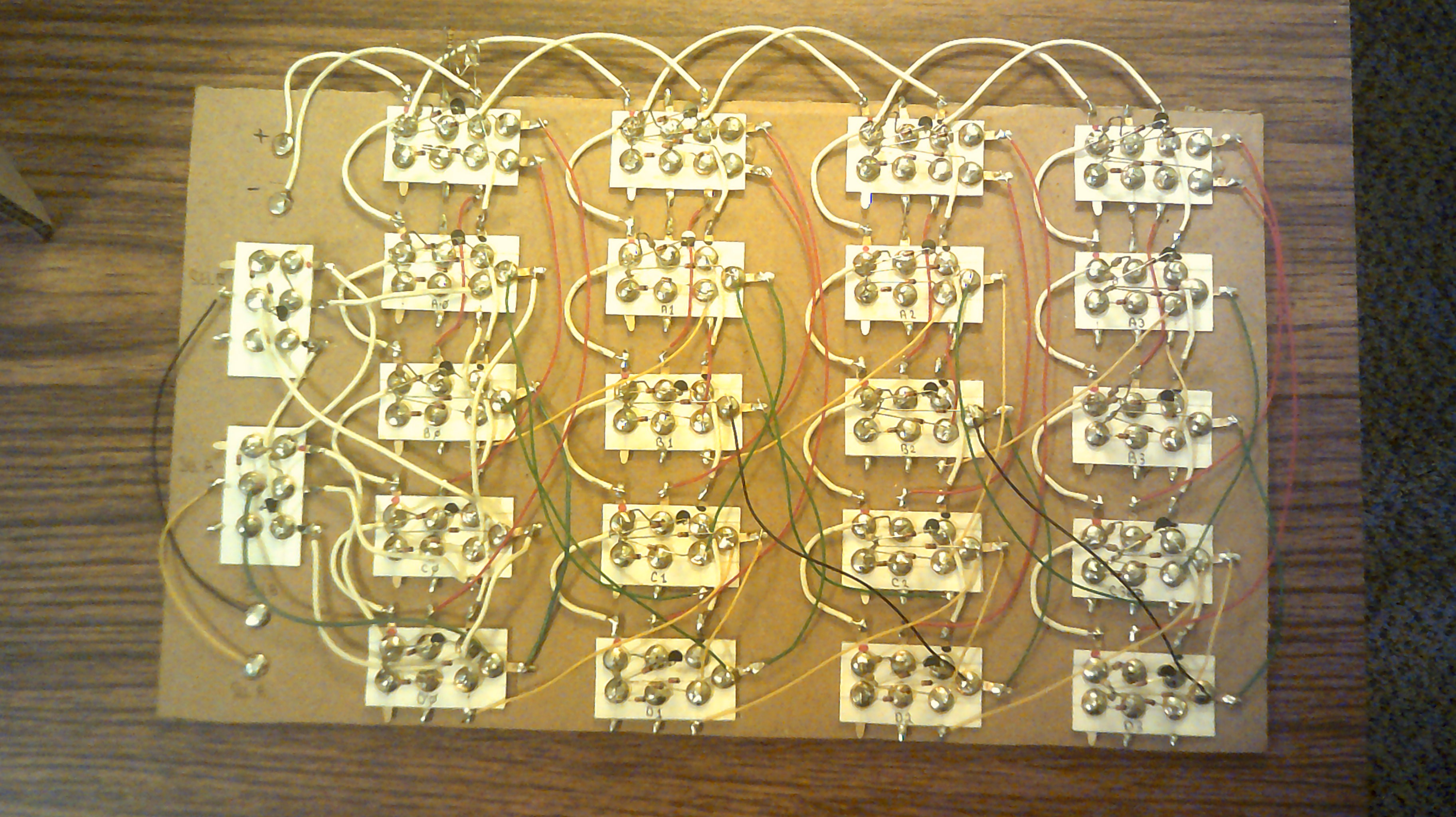
07/02/2017 at 07:36 • 8 commentsThe checkout of the MUX is completed and I am amazed that there are no wiring errors and it works like a champ. I can now start pushing 4 bit data around on the data buss :-)
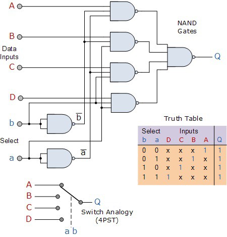
______________________________________________________________________________________________________
This is the finished 4:1 MUX. Now to do a complete checkout...
![]()
Here is the current MUX circuit I am going with. This is for one bit but will expand as needed for four bits.
![]()
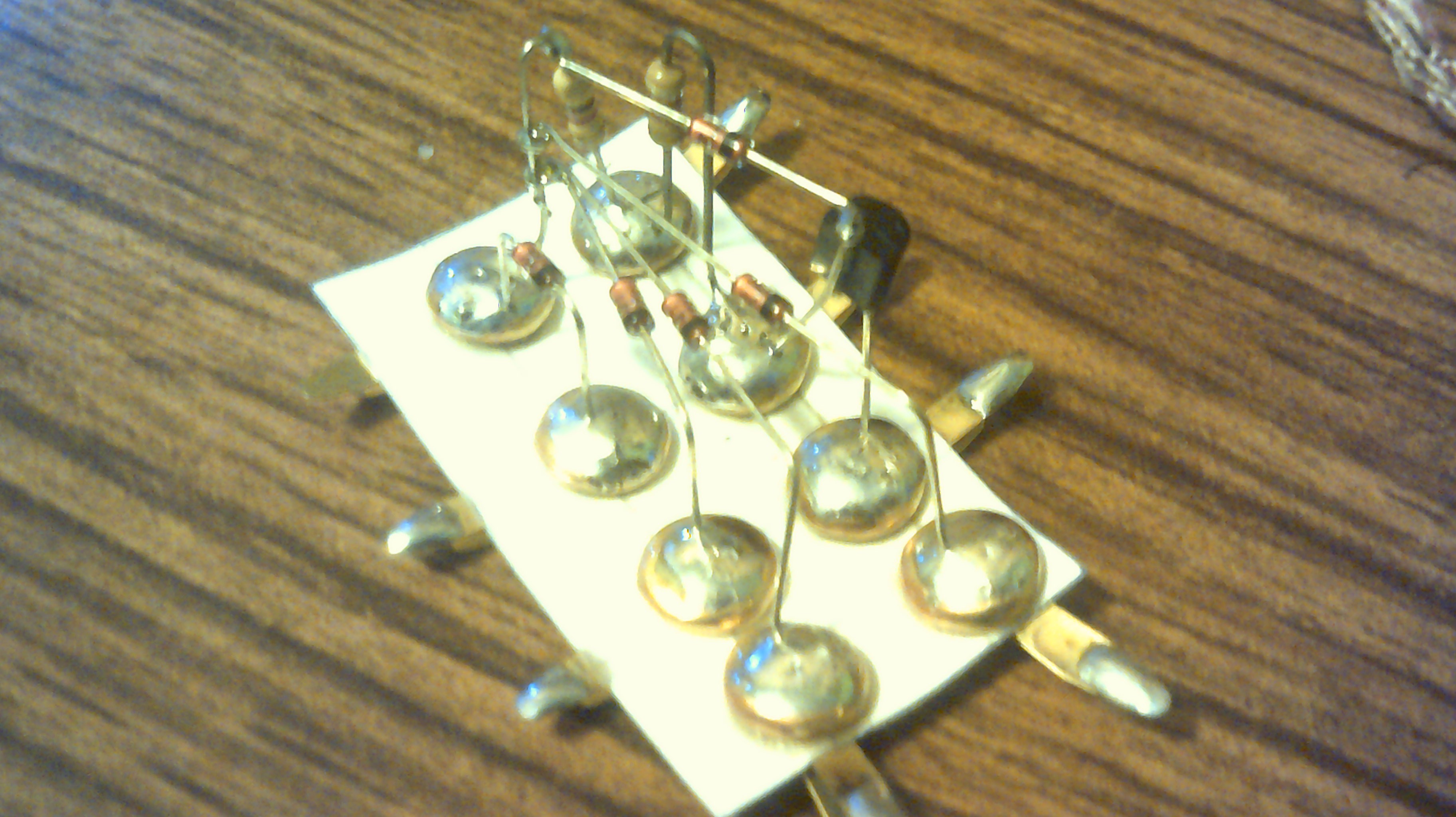
Currently building up the needed logic gates for the 4:1 MUX and here is a sneak peak of one of the four input NAND gates.
![]()
![]()
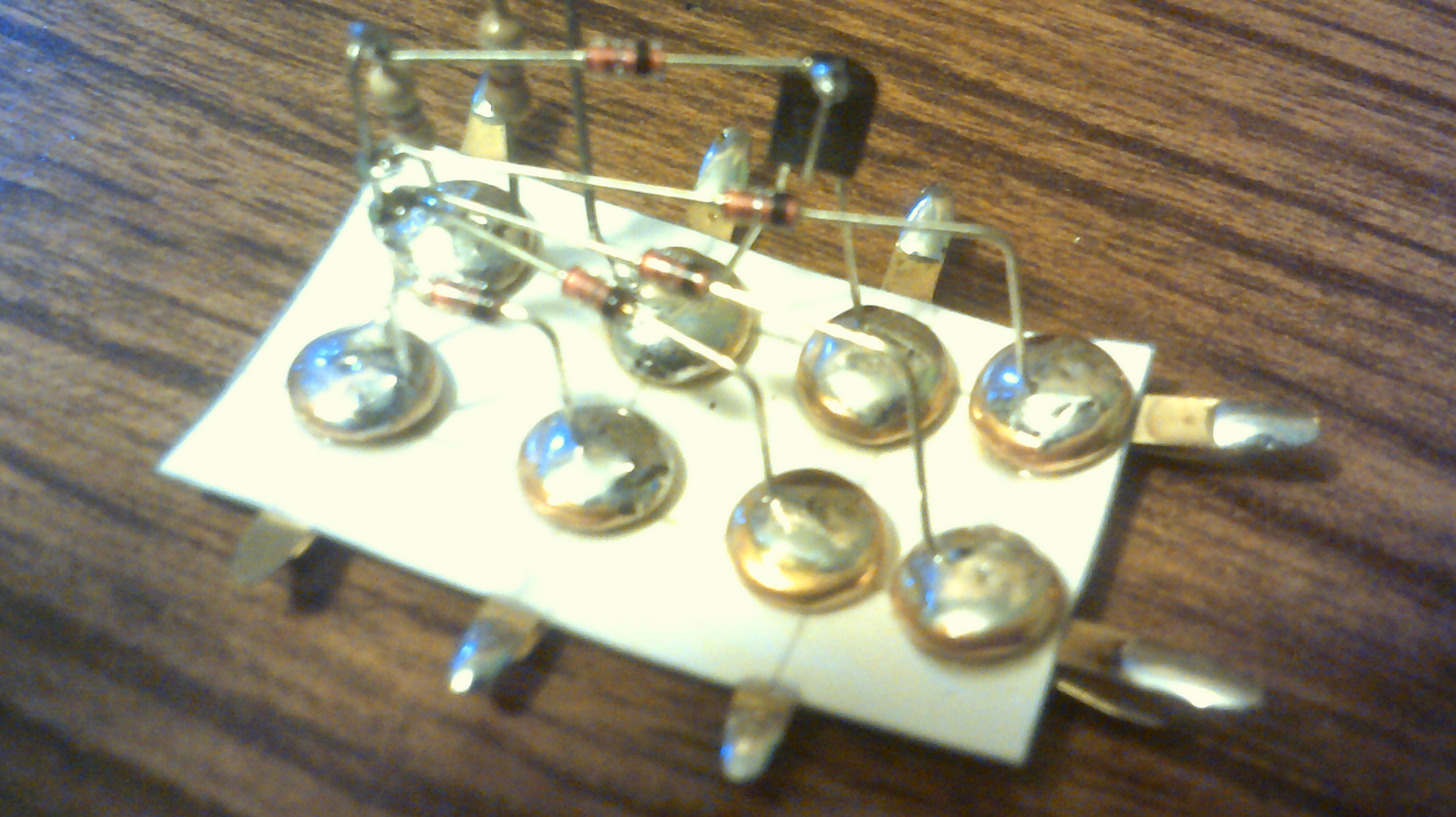
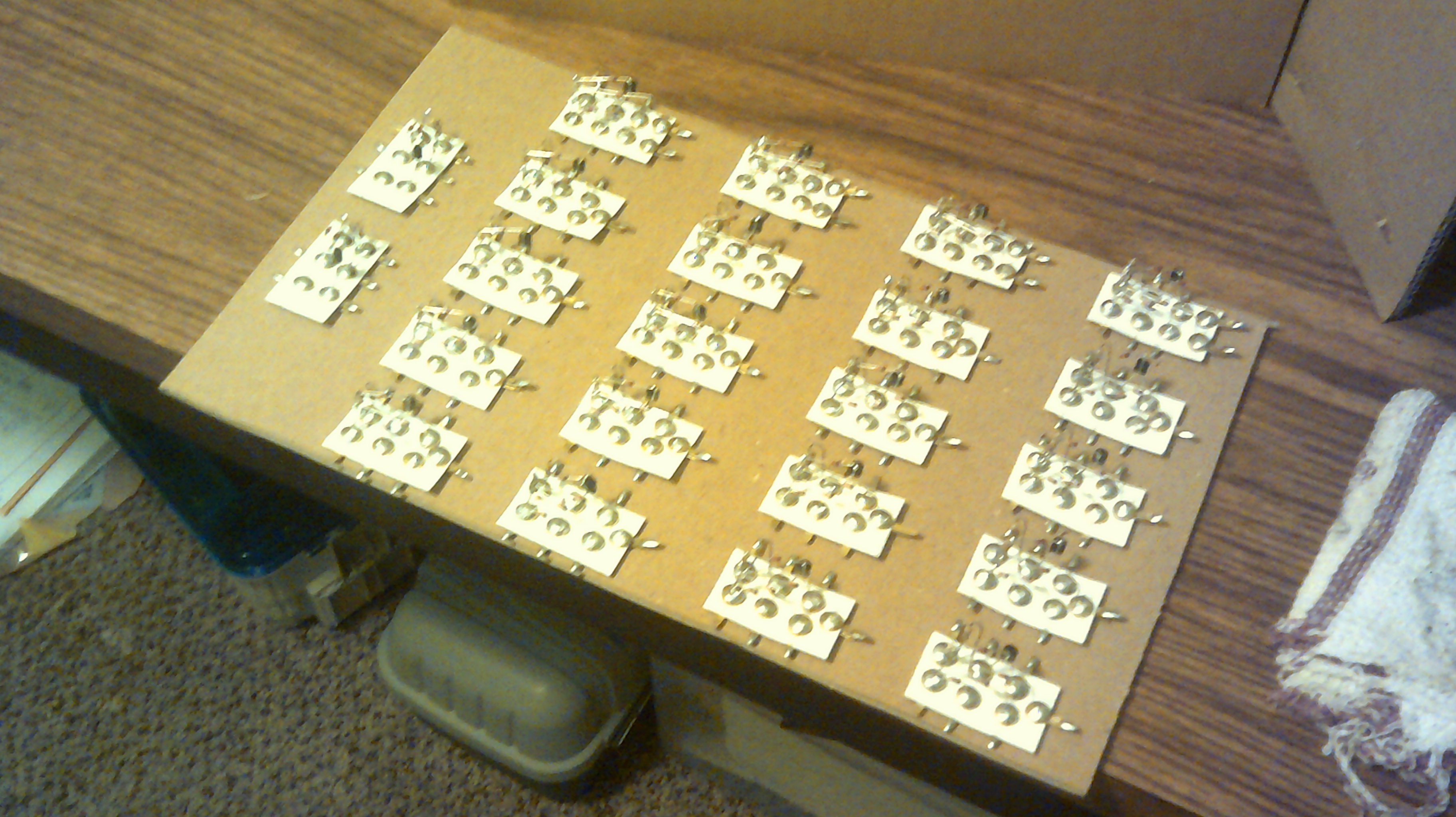
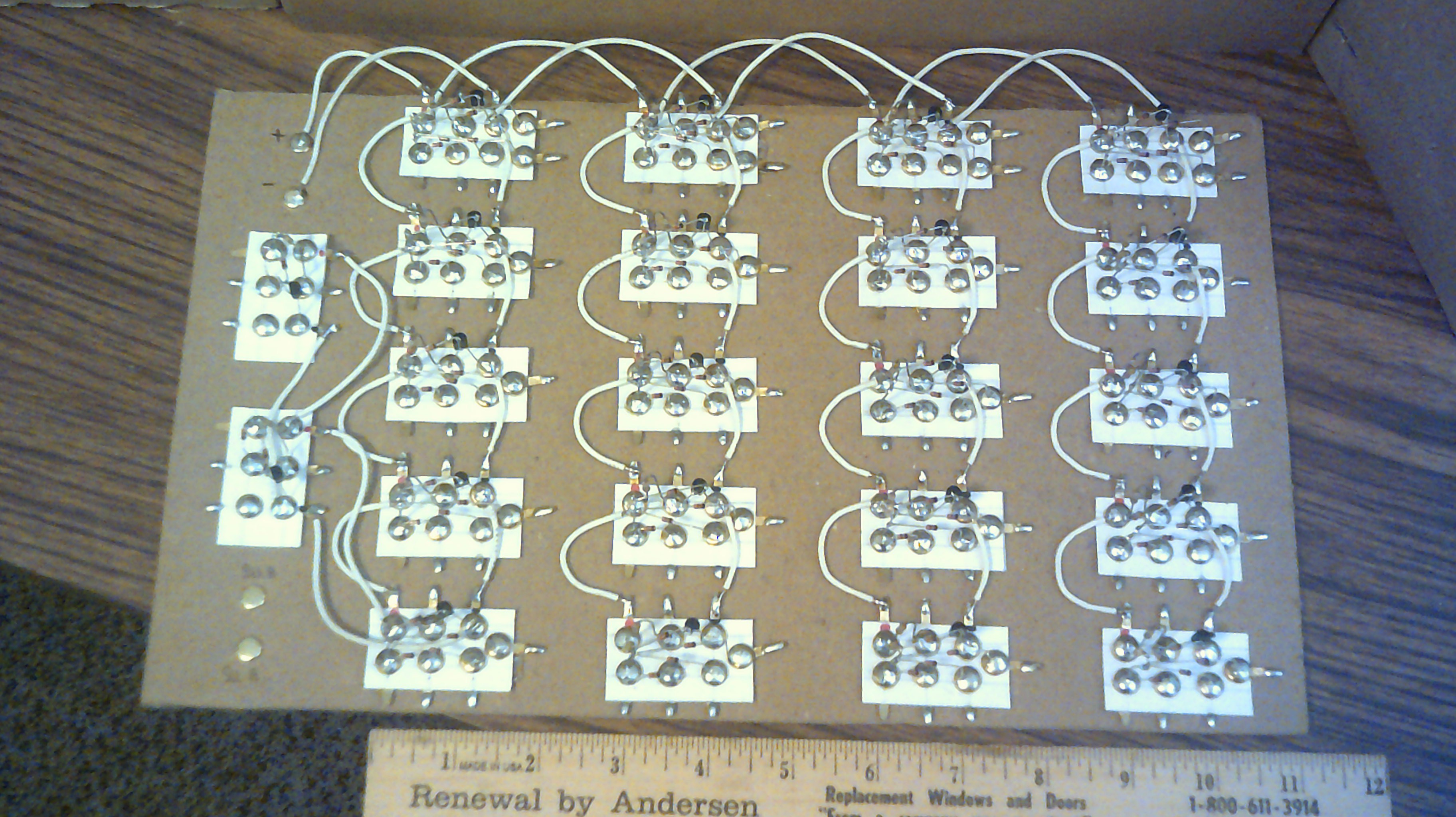
July 6, 2017 - Here is the layout of all 22 gates on their cardboard base. Two on left are the select gates and the four across the top are the outputs. Next is to hot glue them in place then start the wiring.
![]()
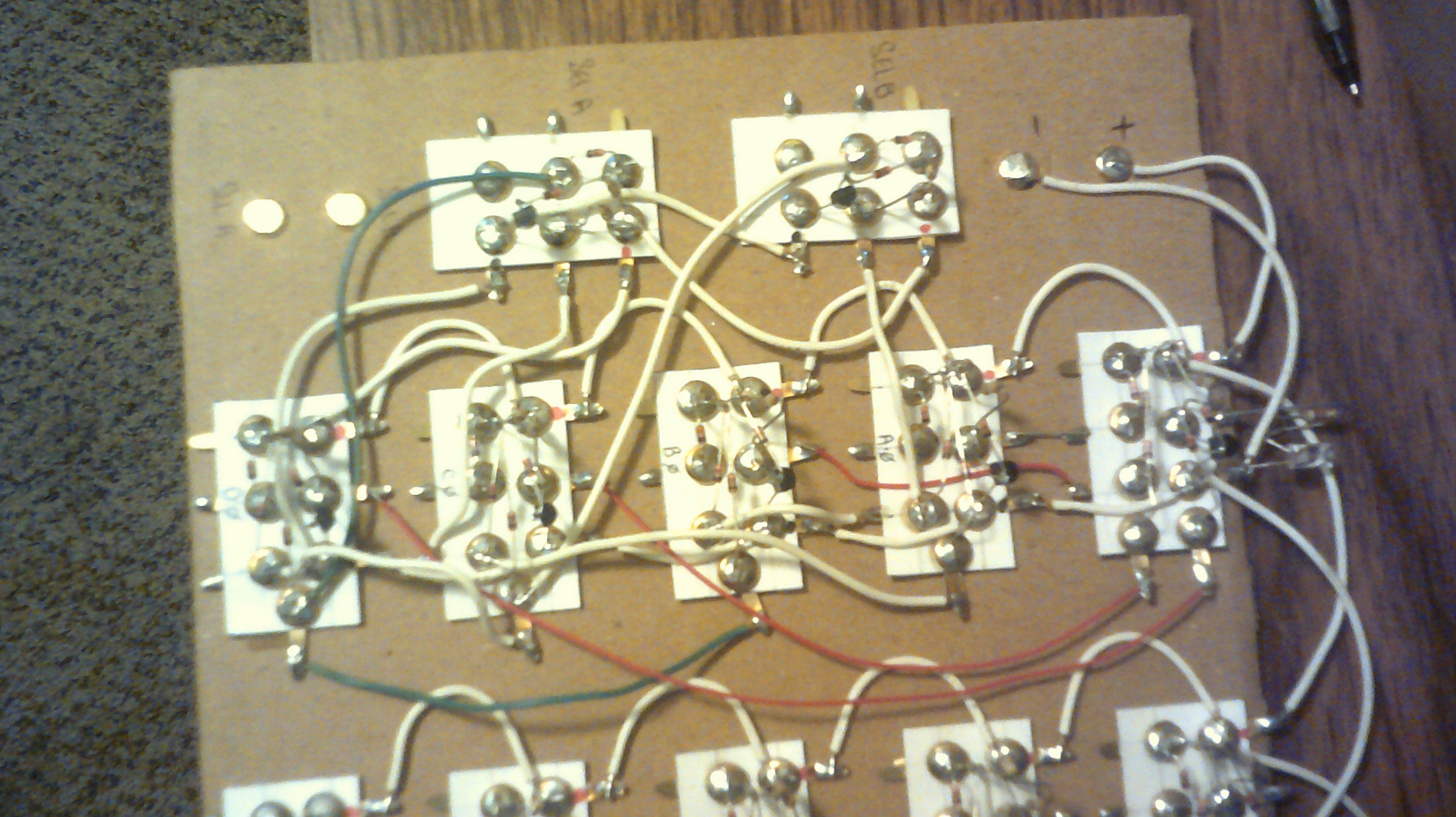
July 8, 2017 - The power and ground wiring is now in place.
![]()
July 10, 2017 - The first bit is wired and passed the selector test between four different inputs to the single output . The wiring looks a bit messy but that's the fun I have with this adventure :-)
![]()
-
June 22, 2017 - The move is done and IO is alive and well
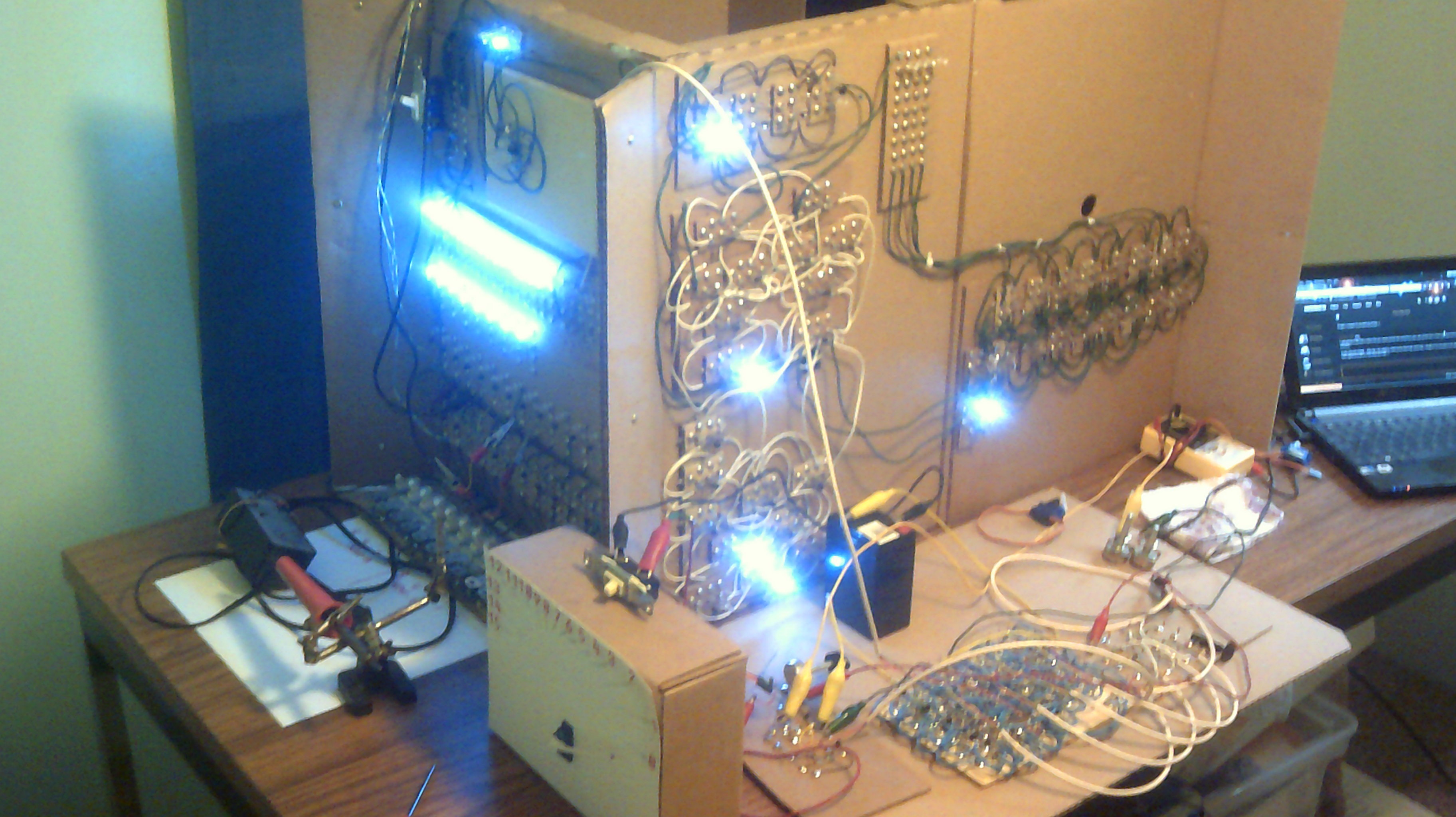
06/23/2017 at 00:18 • 7 commentsI have spent the past month making a move to a new home here on the North Carolina coast and am glad to report that IO has survived the trip. I am now getting the work table and IO set up and ready to continue melting solder :-)
![]()
-
May 22, 2017 - Construction on short hold
05/22/2017 at 23:53 • 1 commentNot to worry, the adventure with IO will go on, however My wife and I are going to move in the next 30 days and I will need to box up all my junk plus IO. This is sudden but needed. Staying in the same county but into a larger home with a real yard to mow :-) Also an out building to store lots of my stuff :-)
-
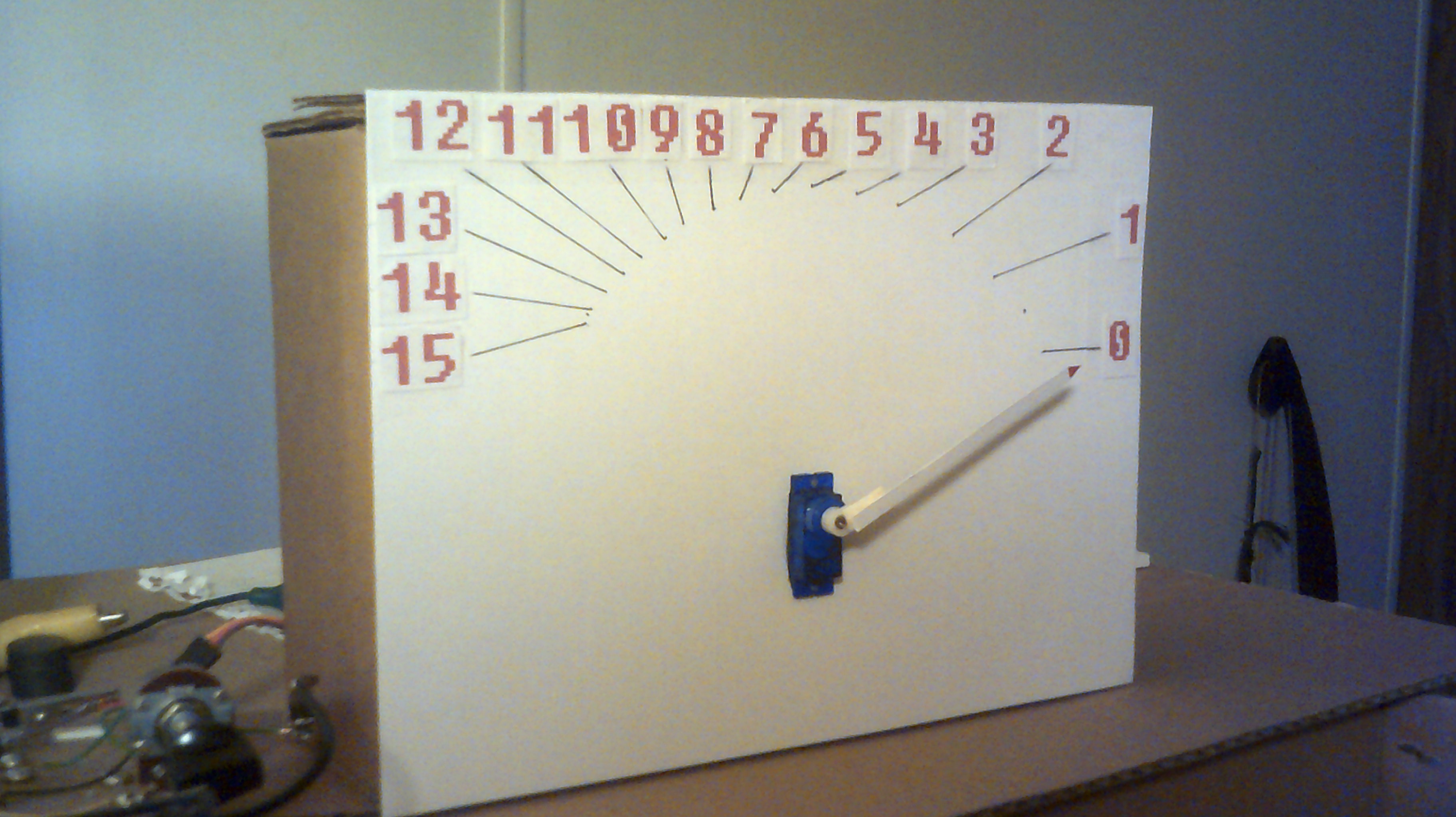
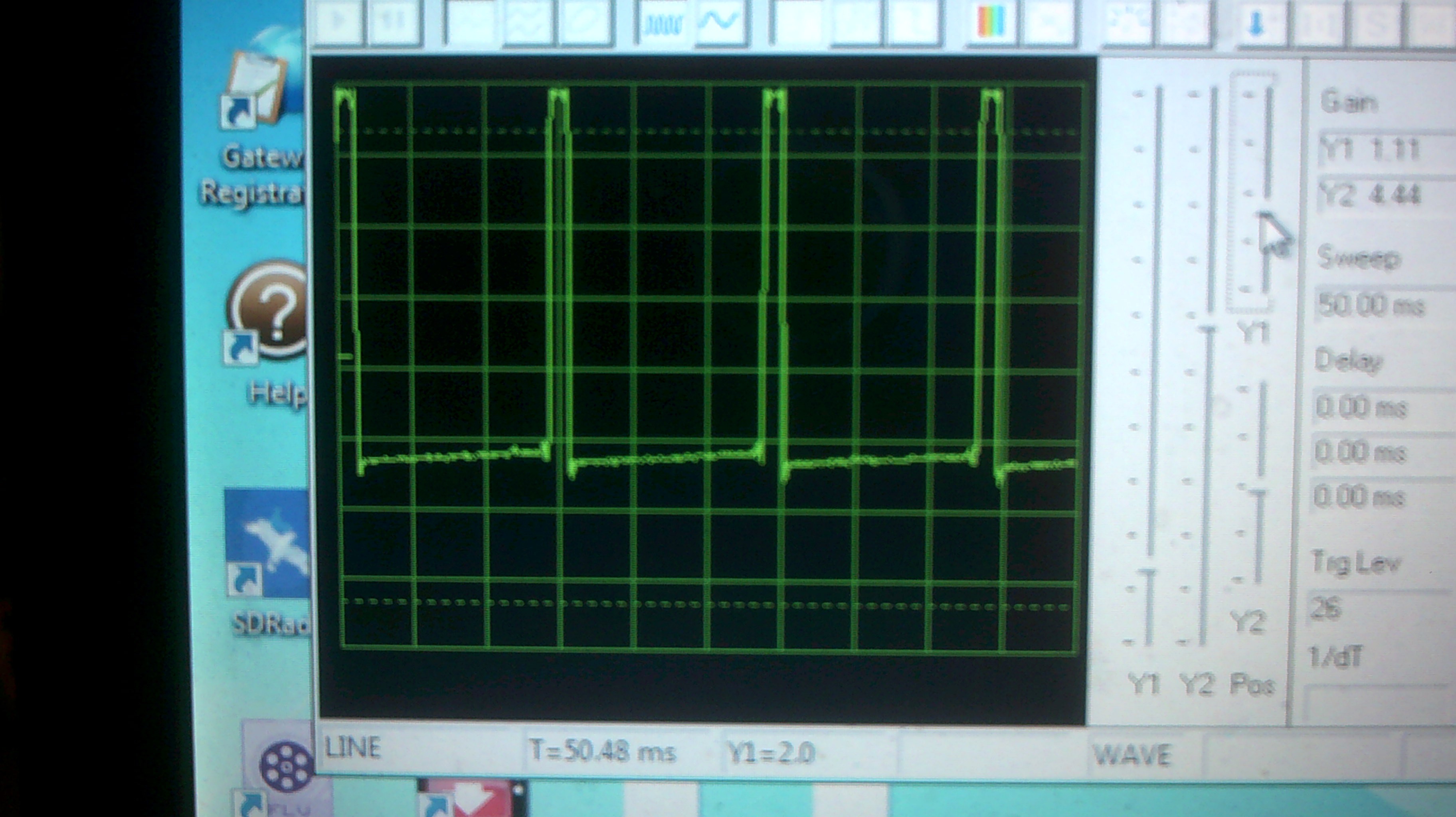
May 16, 2017 - Servo display panel
05/17/2017 at 00:14 • 2 commentsThis is a rough idea for a display panel using a servo to show the output of the ALU. Input is being made with IO's front panel data switches.
This is Uglytech at its best :-)
This is a cleaned up version. Not as ugly but still Uglytech.
![]()
The ALU feeds its output to the 4 to 16 line decoder on the left. The output from the decoder goes to a resistor bank on the lower right and then to the astable multi-vibrator upper right that then sends its output to the servo.
![]()
This is how my Winscope sees the servo signal. Not bad for a simple two transistor astable :-)
![]()
The Cardboard Computer - IO is my name
My goal is a 4-bit CPU using recycled cardboard substrate and Diode Transistor Logic. This is an educational platform for me.
 This is all of whats left of my antique radio collection. These parts need a home and I will give them up for FREE. I have tried contacting the local AWA clubs but no takers. The central radio receiver is a modern build with vintage parts. I would rather not ship so if anyone is visiting the south east NC coast then come on by and the parts are yours :-) I will be in SC for the eclipse on the coast and can have them with me.