-
Light Logic is coming
10/18/2018 at 08:31 • 0 commentsI have decided that the upcoming IO2 project will use #Light Logic gates entirely. This means a CPU/MCU with out transistors, relays or vacuum tubes for ALL of the logic circuits.
-
A fairwell to IO but looking forward to IO2
08/28/2018 at 19:52 • 8 commentsHere it is August 28, 2018 and I have decided that IO has reached its limit. I have learned a lot from this project but IO has has grown to the extent that I no longer have enough room to work on any other projects and I might be moving away from the coast in the next year.
I will be saving IOs boards either for future use in IO2 or will use the parts on other projects. I wish to thank everyone here on Hackaday for their support and look forward to the same support in future projects.
There are no set plans for IO2 except that it will be much more modular in design.
-
Still on hold but not for long
07/19/2018 at 23:45 • 0 commentsHere it is July 19, 2018 and IO is still on hold as I continue to work with other projects for this years HaD contest. I have decided that I wired myself into several corners on IO and once work resumes, I will revise some of the sections and make other improvements as I come across problem areas.
Thanks for all those who are followers and there will be more of IO and later, IO2
-
IO is on hold - May 30,2018
05/30/2018 at 10:24 • 0 commentsDont panic everyone, I am giving IO a vacation while I work on #ColorChord for the 2018 contest. I had to borrow a couple of parts from IO but it is still in fine health :-)
-
K.I.T.T. meets Carr..dboard
05/06/2018 at 22:42 • 12 commentsWell it's time for a little fun for a change and @davedarko this for you :-D
Thank you @danjovic for the new title :-D
Was wondering what to do next with IOs construction and @Morning.Star gave me an idea that tickled my funny bone :-)
So watch the video and enjoy...
-
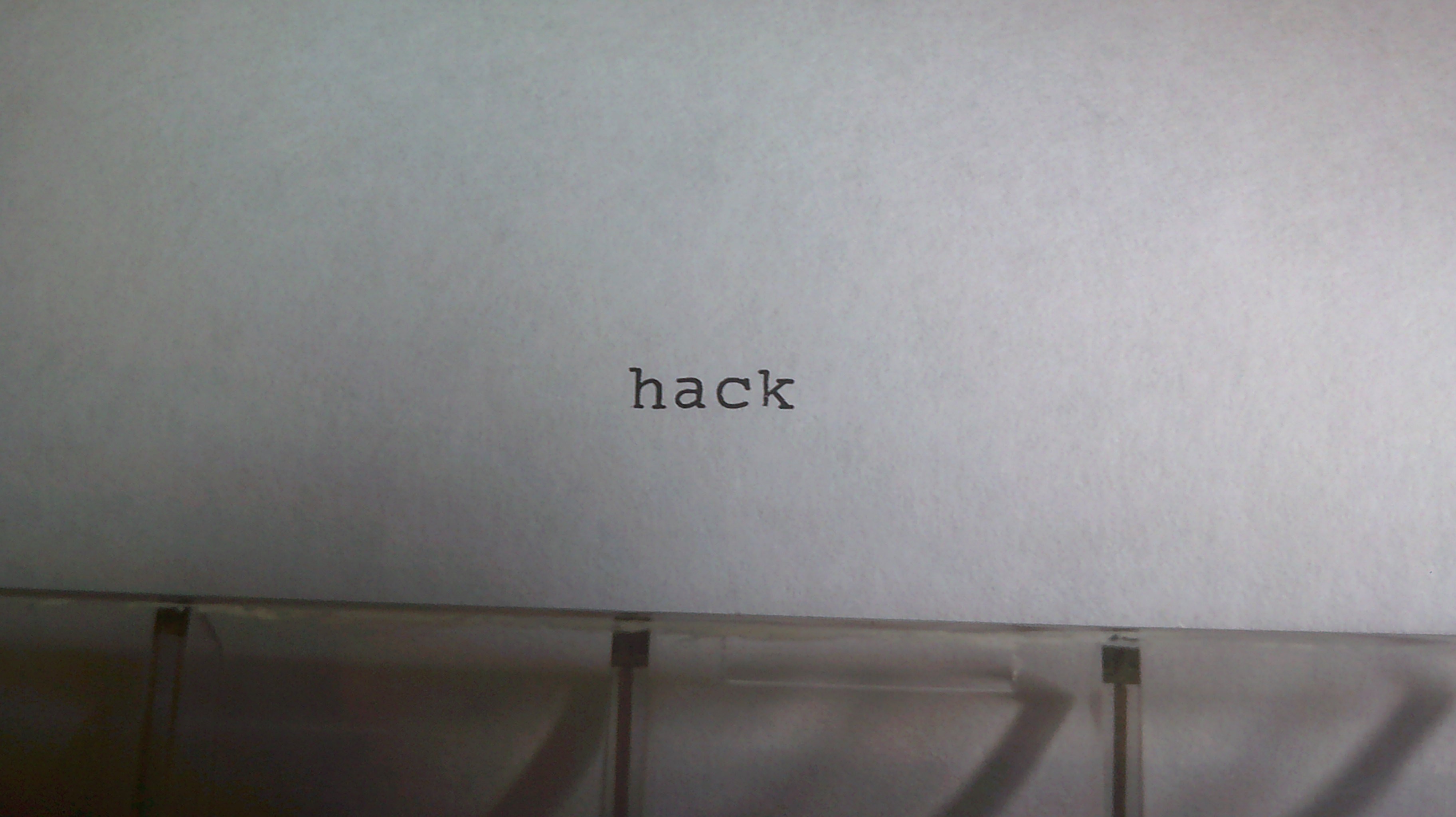
First printed word for IO - April 11, 2018
04/11/2018 at 19:30 • 13 commentsFinally have been able to get IO to print out its first word. The home made opto-couplers had a little light leakage issue near the leds but sealed that end off with black silicone and now all of the circuit is working as desired :-)
-
Opto-Couplers for IO
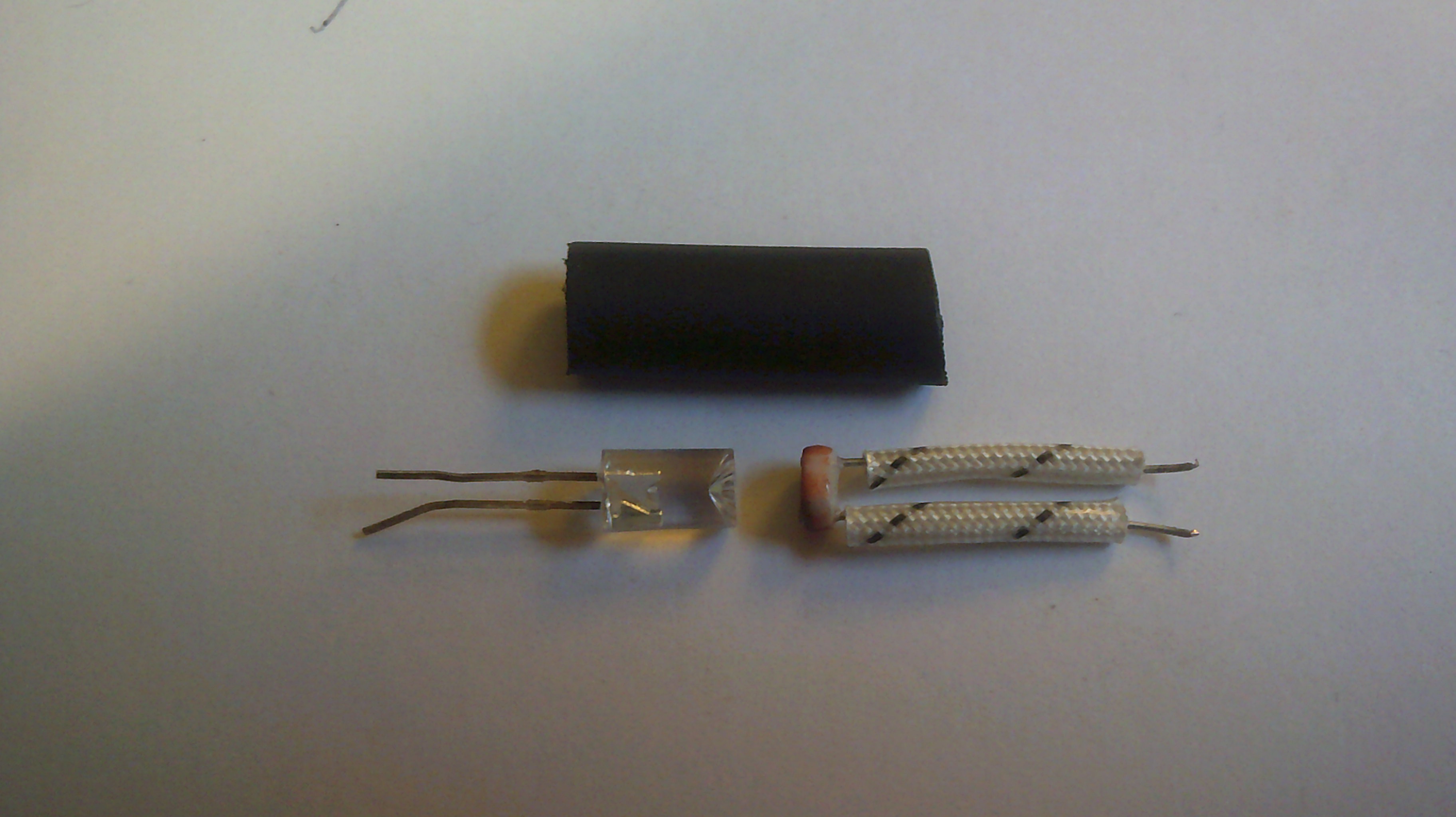
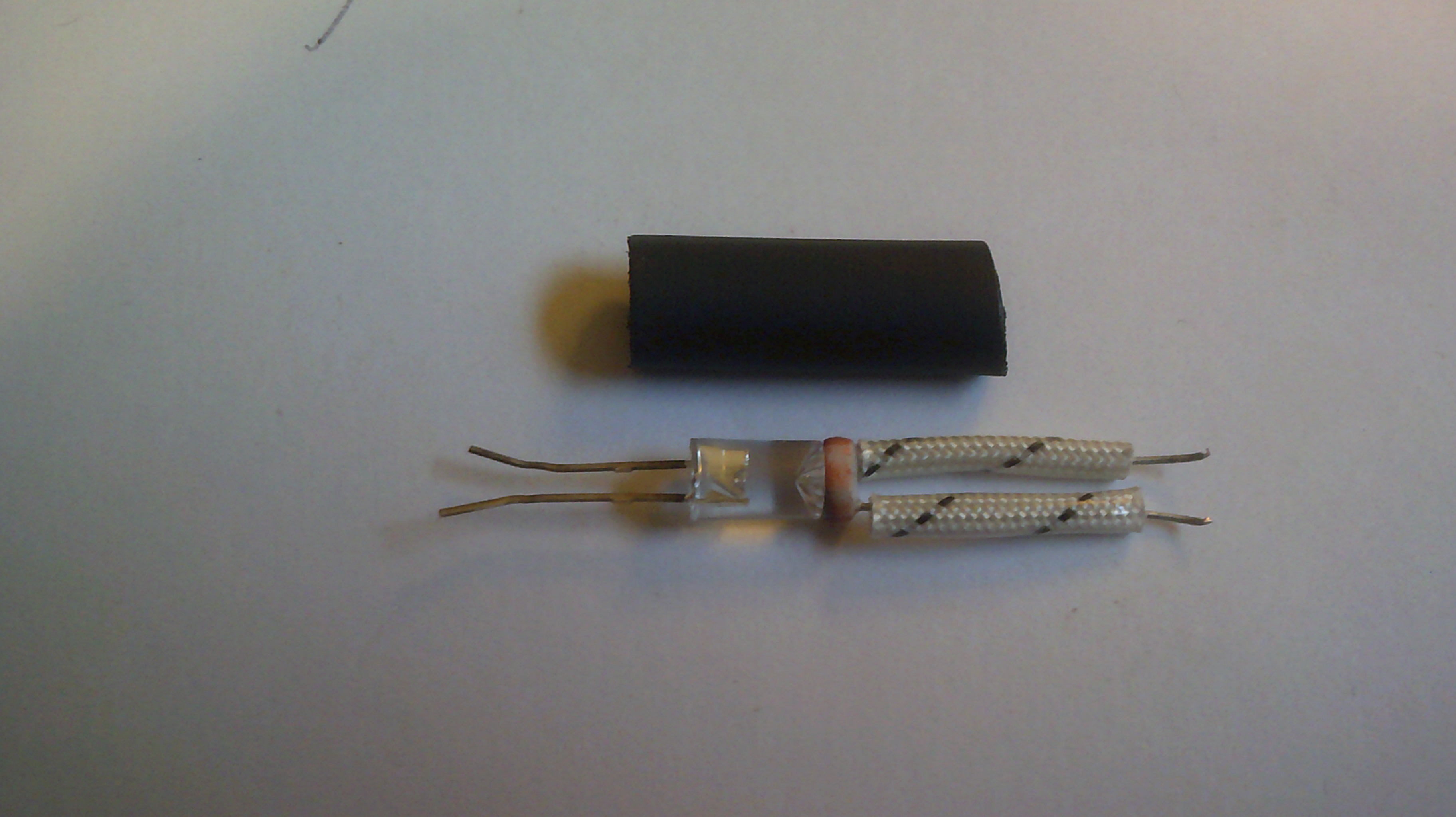
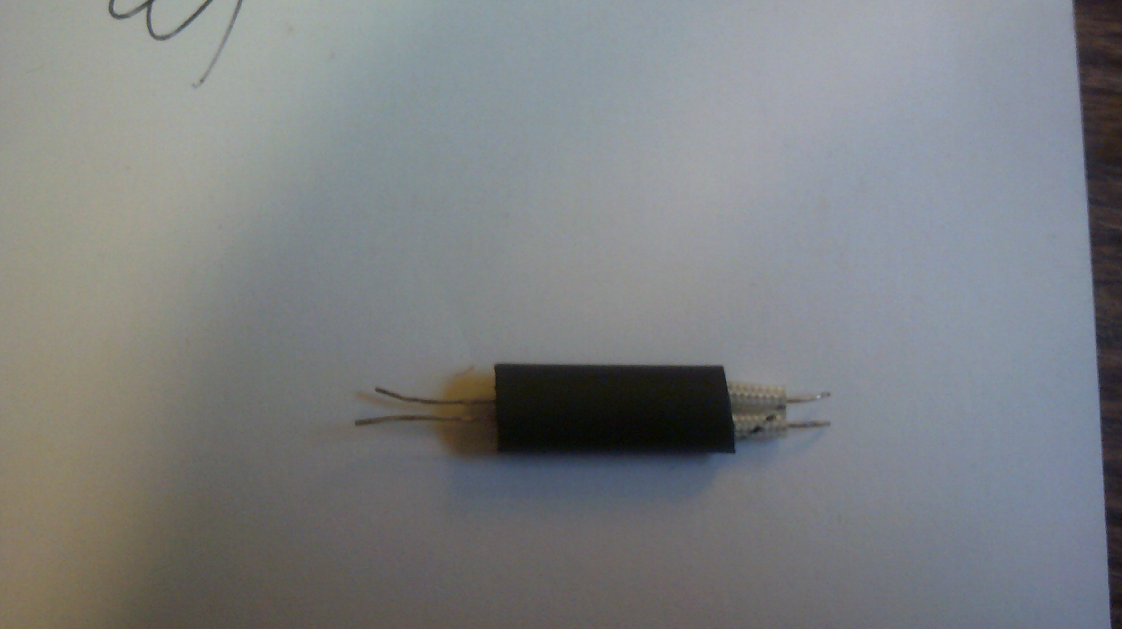
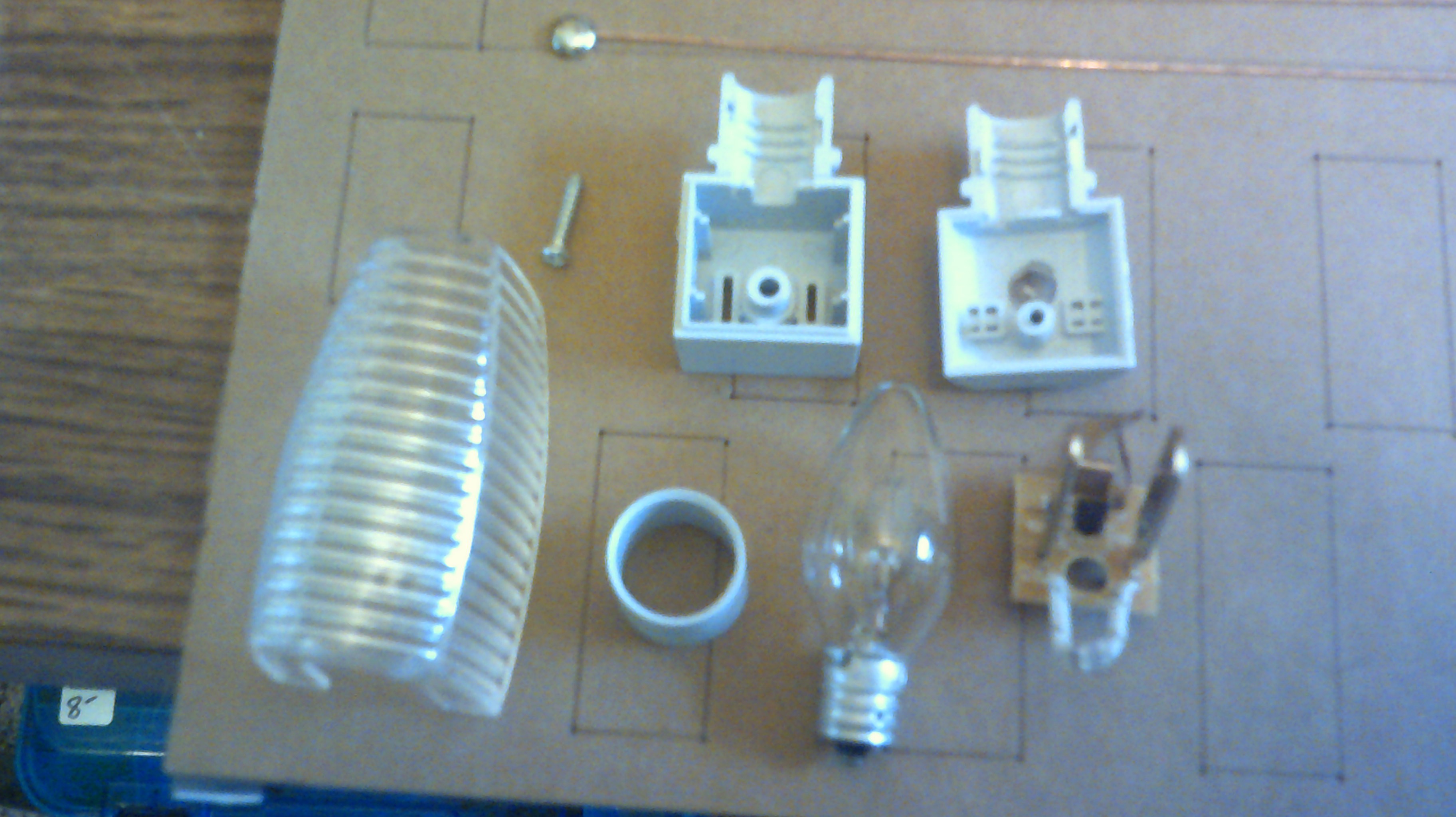
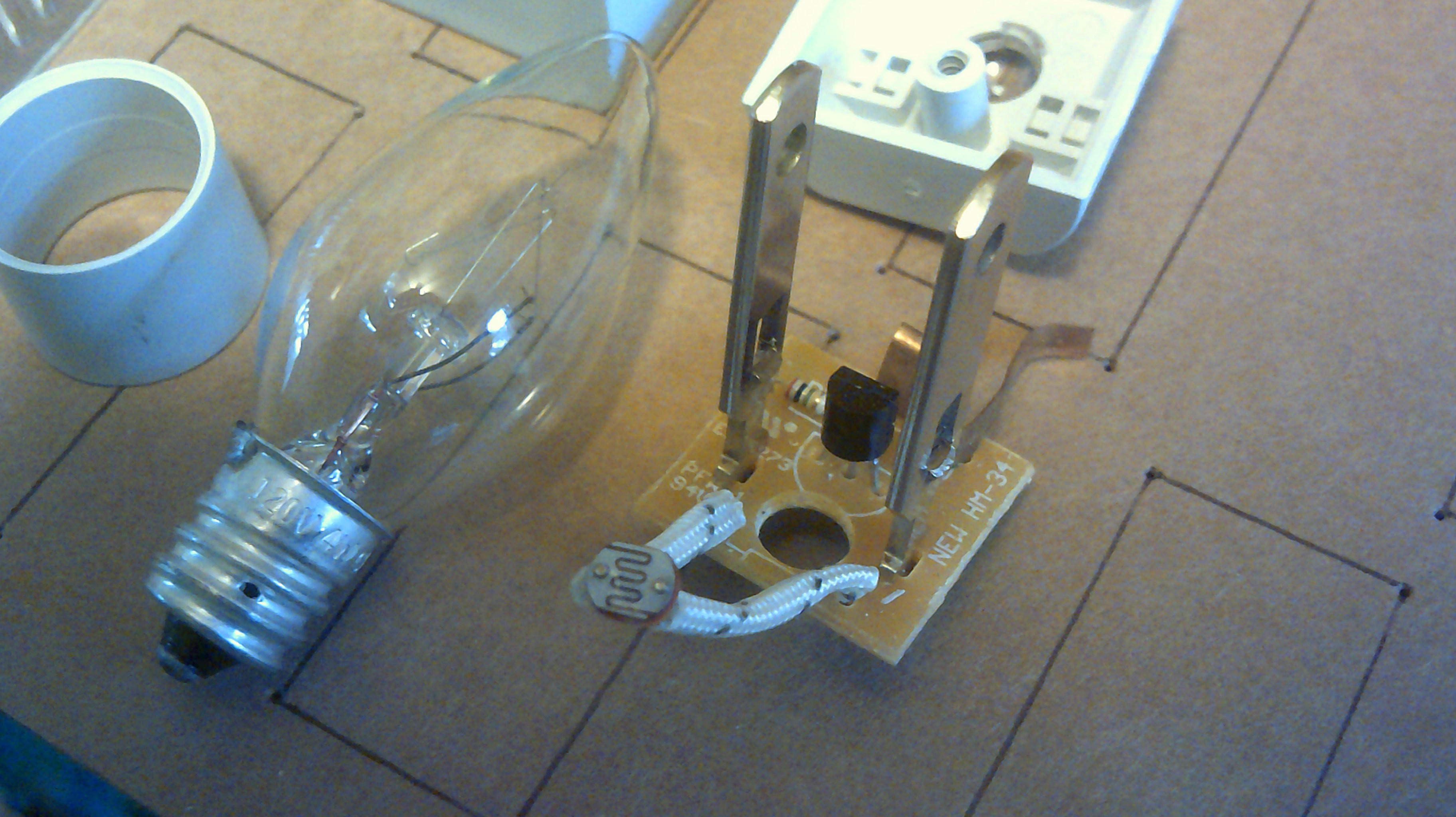
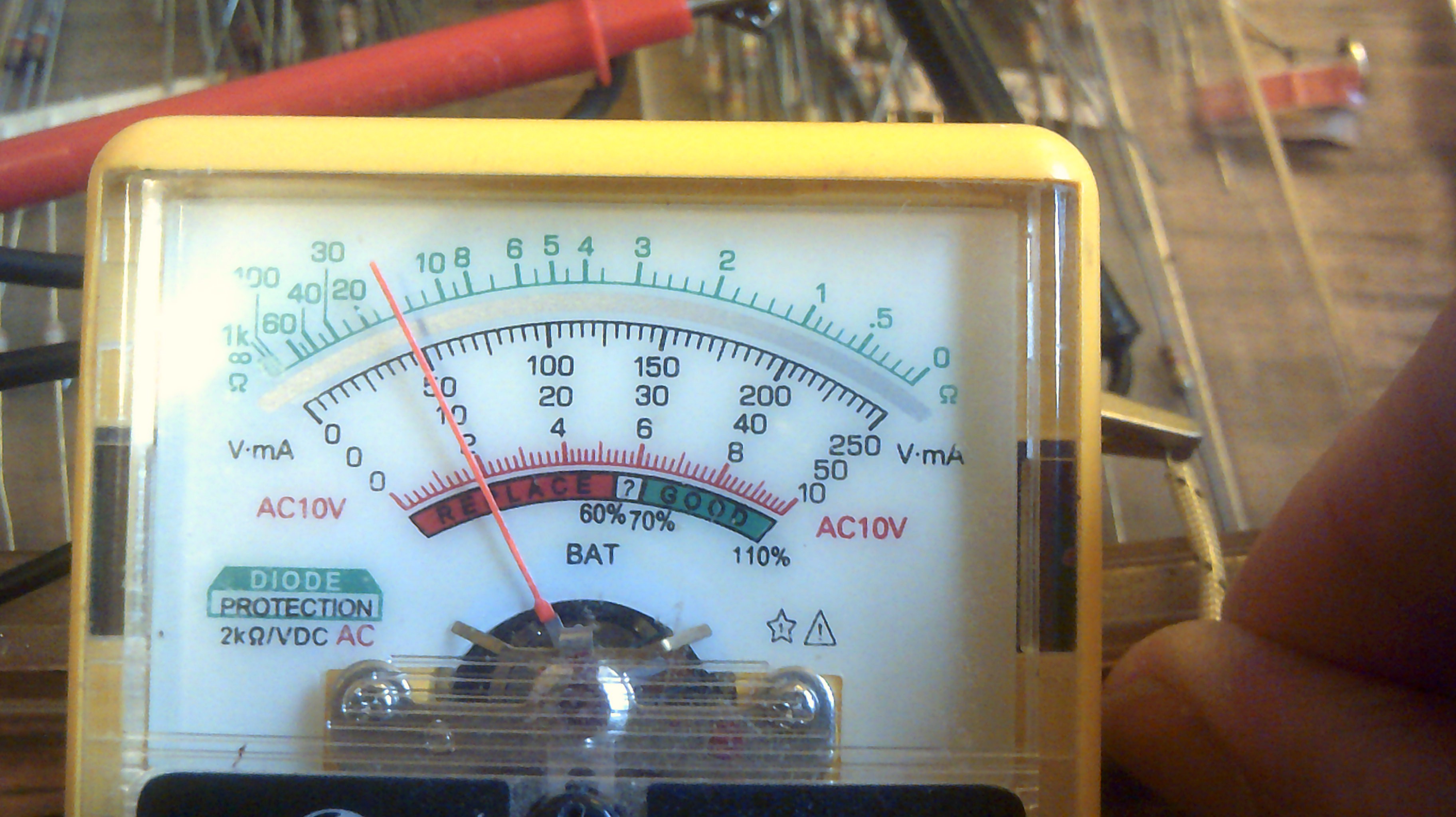
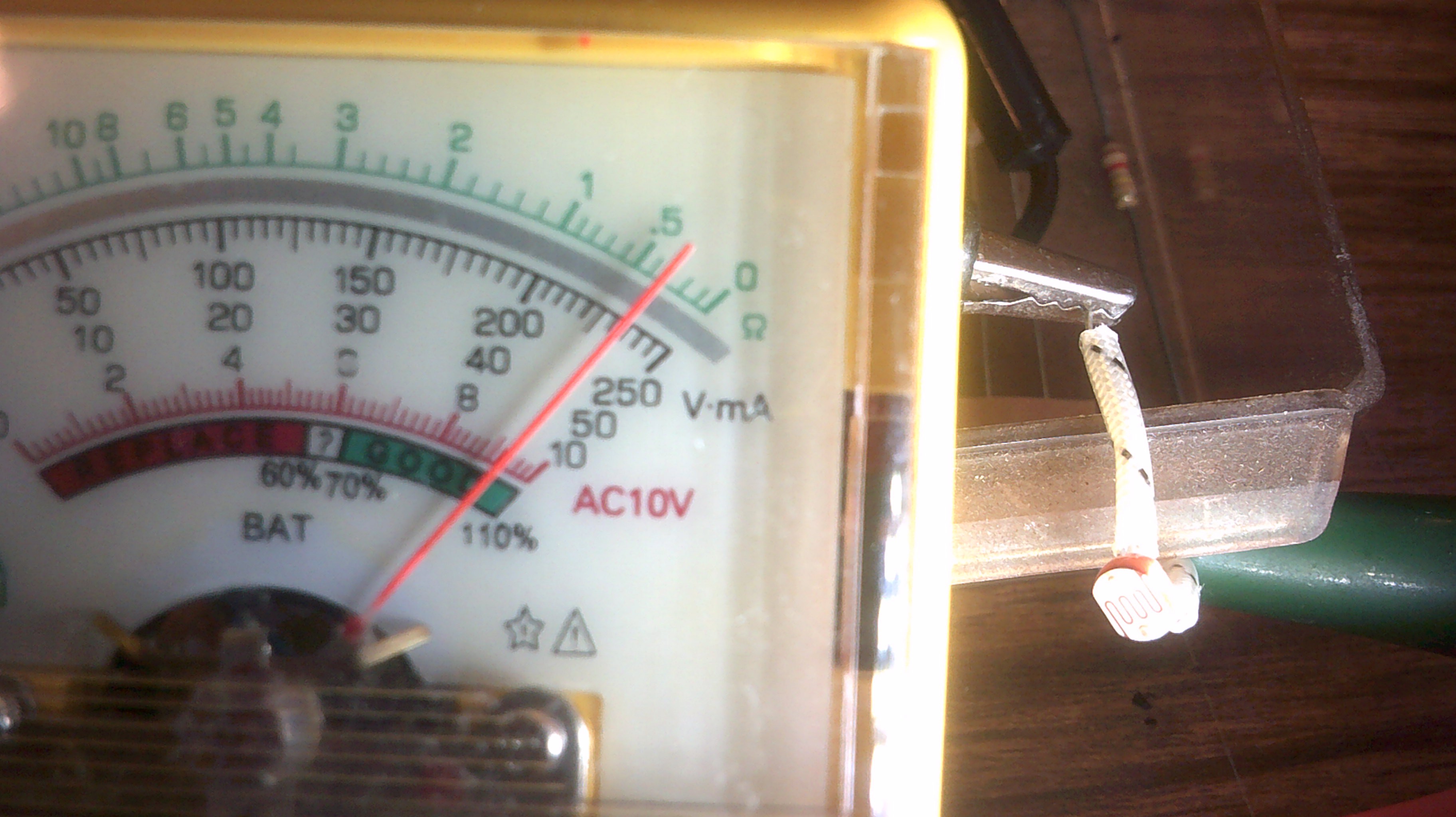
04/09/2018 at 23:25 • 3 commentsI have decided that even though the relay will work as isolation for the printer signals, I see that it would take a lot of time to perfect and build the number that I need. Sooooo, I am rolling my own opto-couplers. @Morning.Star provided the seed to go this way and it is so simple. The CdS cells are from old style night lights found in area thrift stores and the Leds I already have so take a look at the construction images and smile a little. BTW I have seen this method else where on the internet and it works quite well. With no light the cell has a resistance of 15k ohms and full led light it goes down to 400 ohms. IO and the printer work well with it.
The night lights are being sold cheap as they have old style incandescent bulbs and folks these days want the Led type. Better for me in finding cheap parts to hack with :-)The SCR? and 1meg resistor might find a use later on.
Good swing in resistance.
Here is a very short video of two couplers connected between IO and the printer. No timing or signal level issues :-)
-
A cardboard relay for IO - March 21, 2018
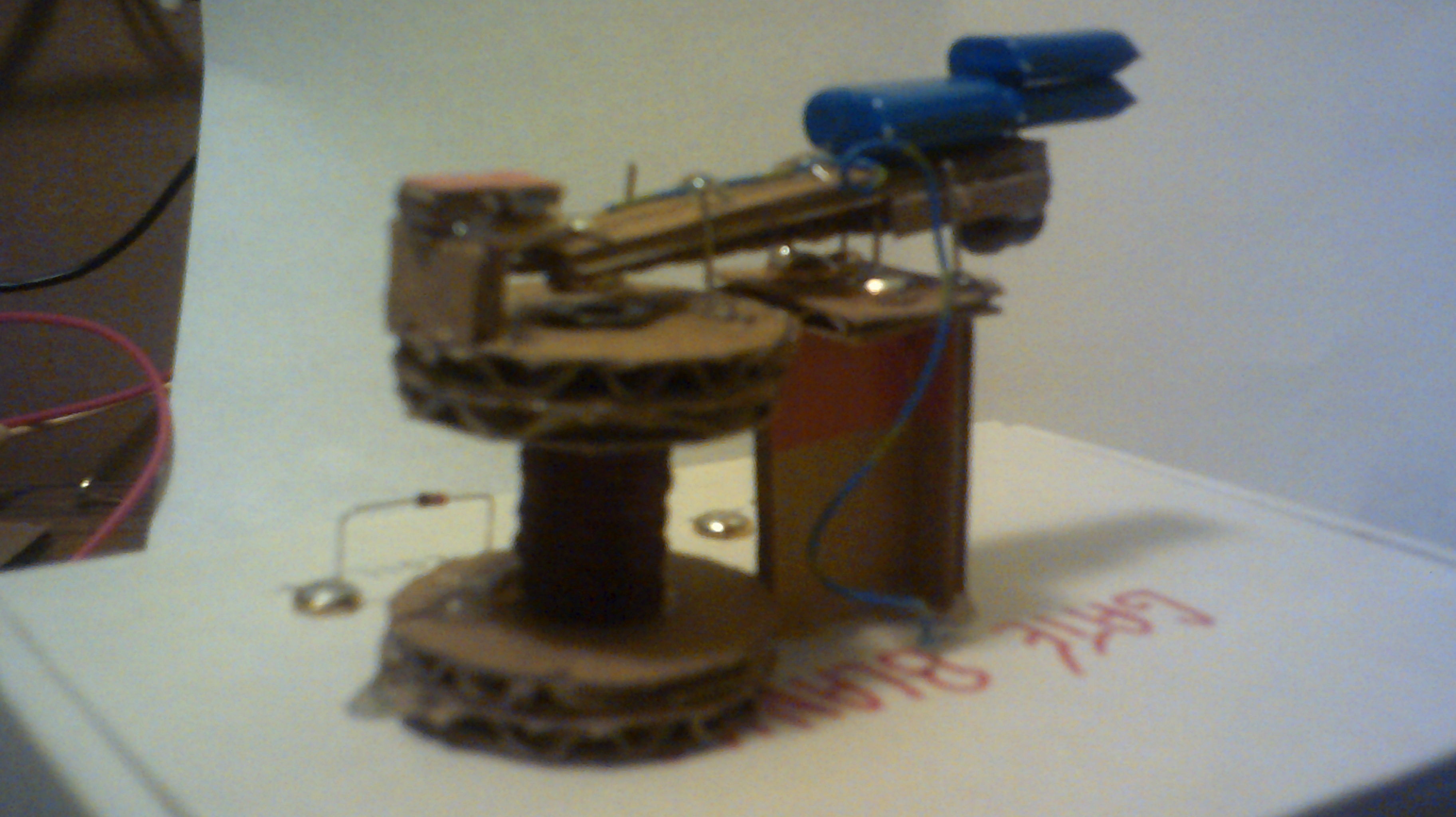
03/21/2018 at 10:58 • 2 commentsHere is the second version of the Uglytech relay. I will try this for signal isolation to the typewriter/printer. Still needs work but getting better at this...
This video shows that the relay does work with both IO and the printer Note the screw and nut added to adjust gap.
-
A possible output device for IO
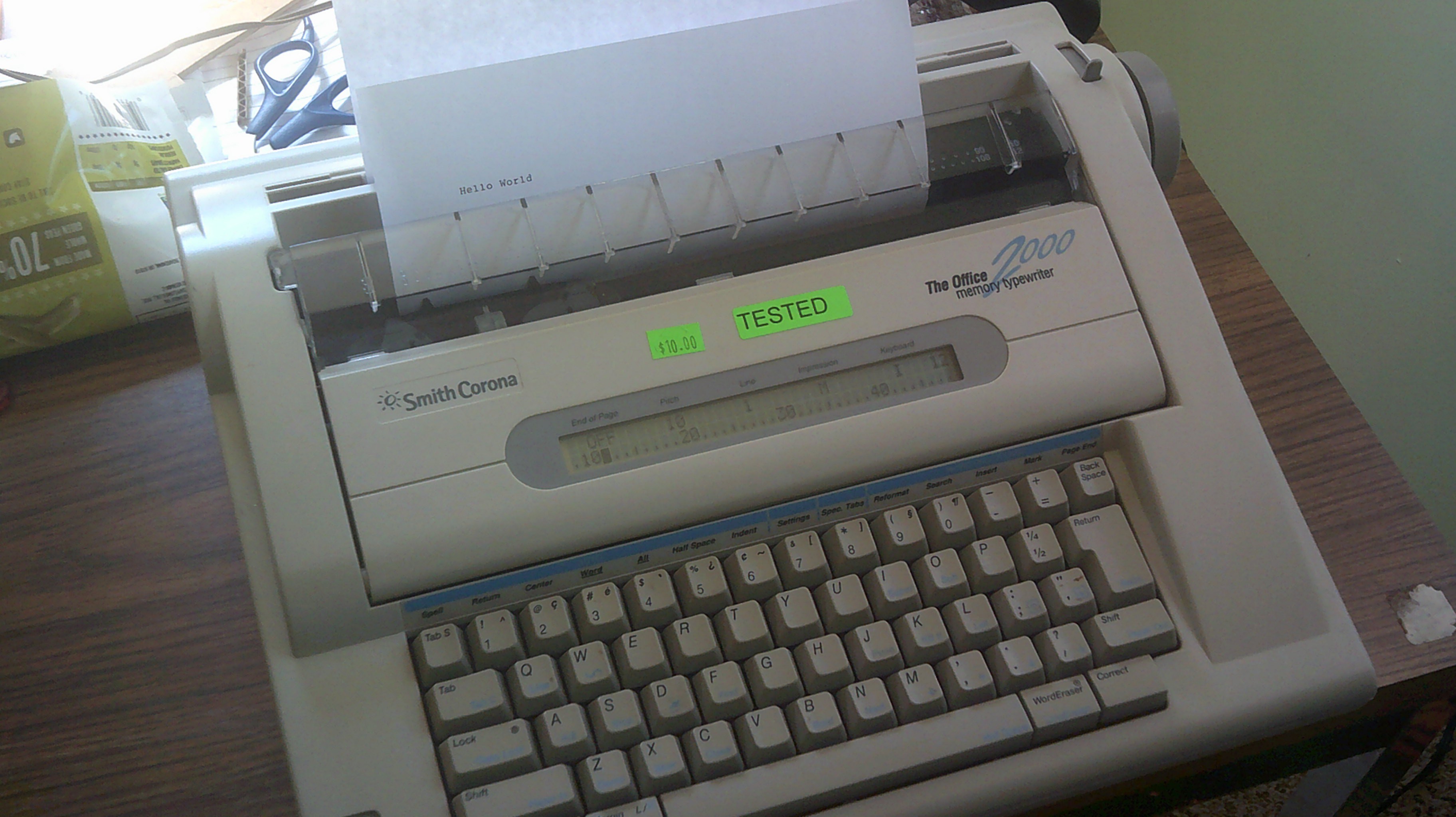
03/02/2018 at 17:11 • 7 commentsFound this Smith Corona Typewriter for $8 and it works fine. No, the Hello World is not from IO... I might be able to patch IO into the keyboard electronics so please pray for me on this one :-)
The keys press a small rubber? coated finger across the meshed contacts so I think that the contact is acting like a capacitor. Going to begin mapping out the matrix...
So far so good. The contacts are simple make and break. Makes the use with IO a little easier :-
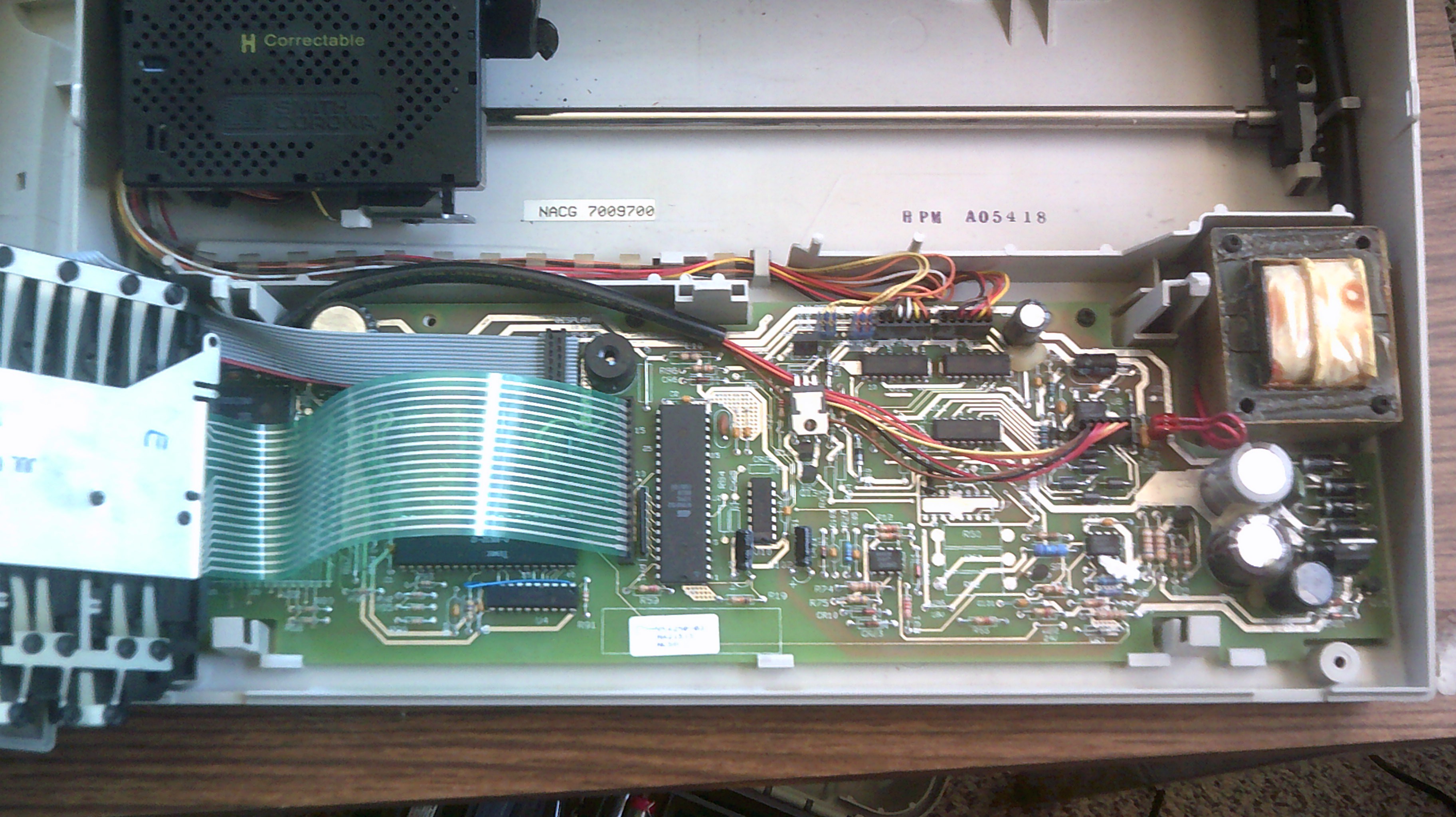
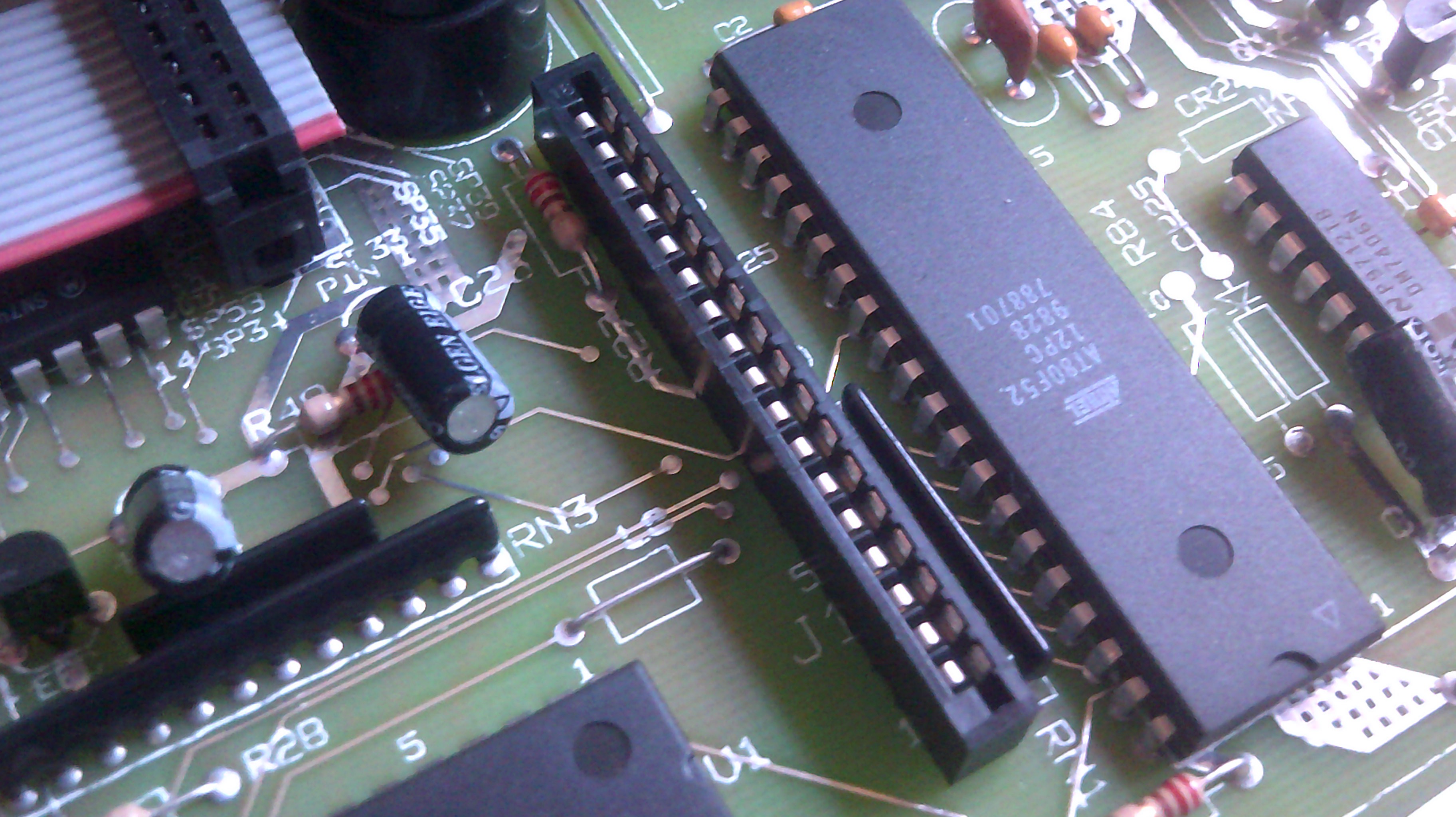
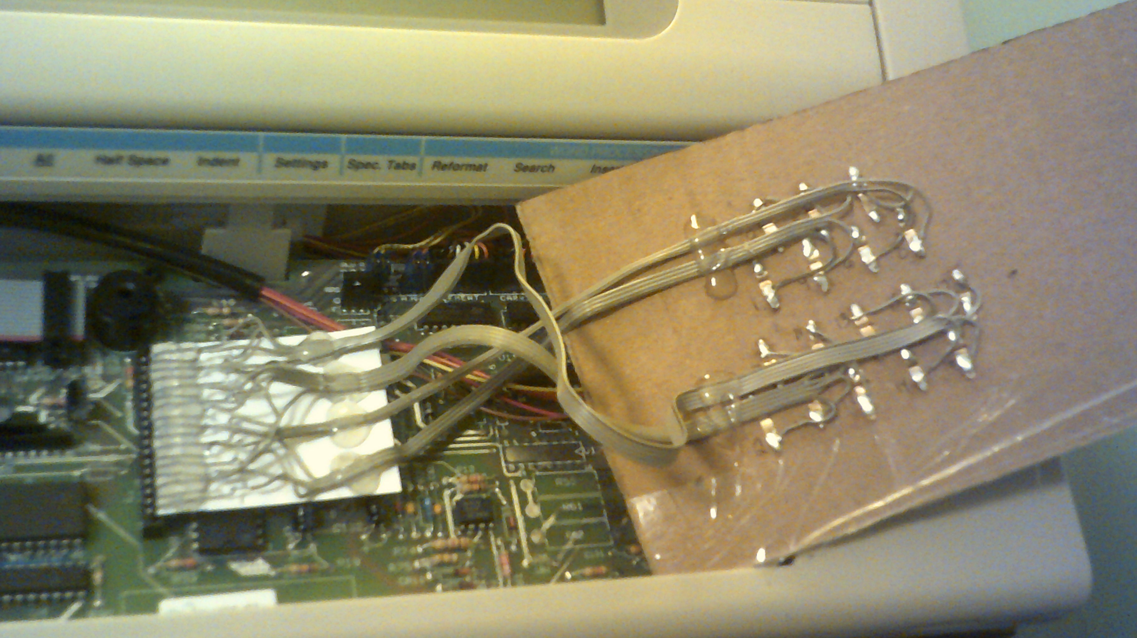
So here it is March 4, 2018 and I have cobbled up a plug in adapter to where the keyboard ribbon cable connects to the main board. Take a look at the progression and either shake your head or chuckle a little but the connection is rock solid.
At least this way I can restore the typewriter back to the way it used to be later :-)
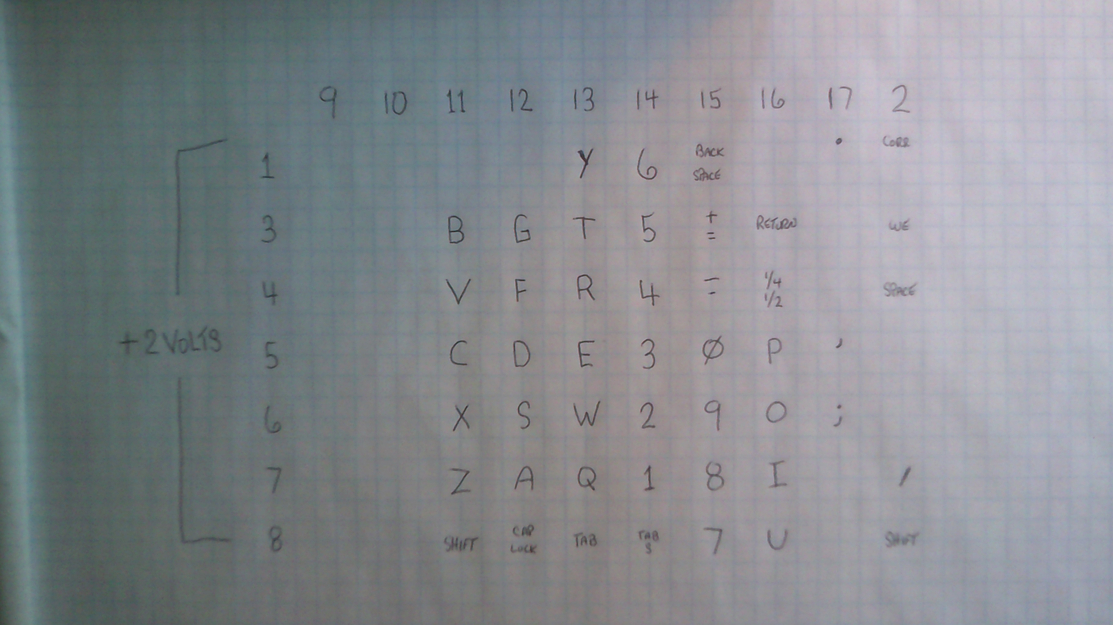
Here is how the connector has mapped out.
All wired up and ready for input from IO :-)
Just at the point where IO is able to send a signal to the typewriter with each sequencer cycle. This is just the beginning. -
ROM card read logic board - March 2, 2018
03/02/2018 at 13:03 • 12 commentsUpdate May 5, 2018 - IO's failed audition as K.I.T.T from Knight Rider :-) But not bad for just four leds.
Just having some fun with the instruction cards
The ROM instruction board all finished and tested. Now need to wire up more cards.
Update May 1, 2018 - All of the logic is wired and the board tests OK after finding one shorted wire.
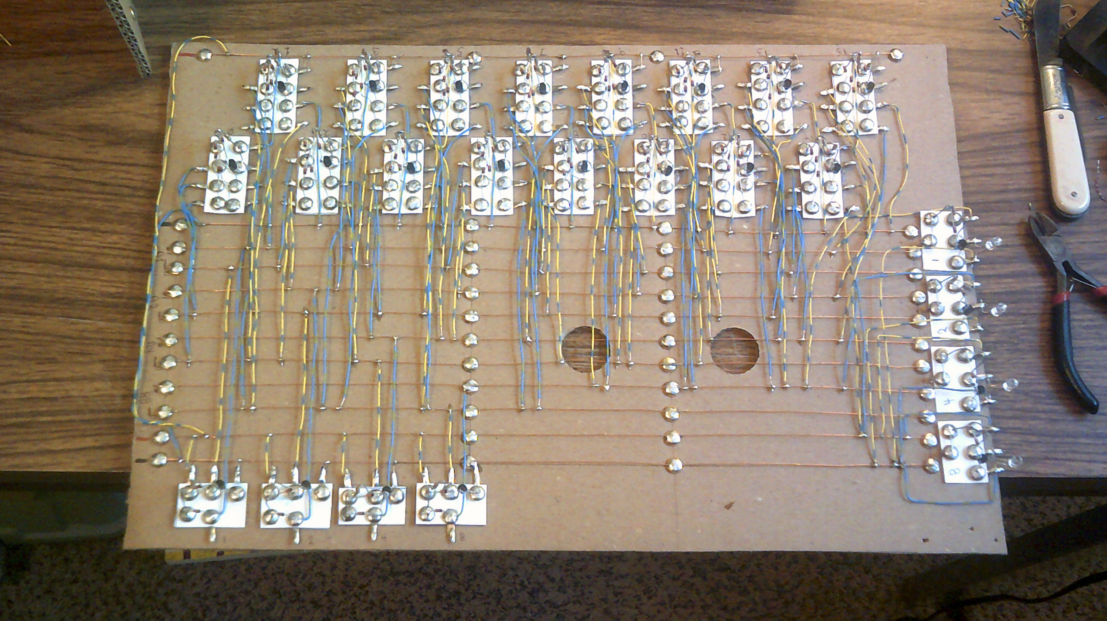
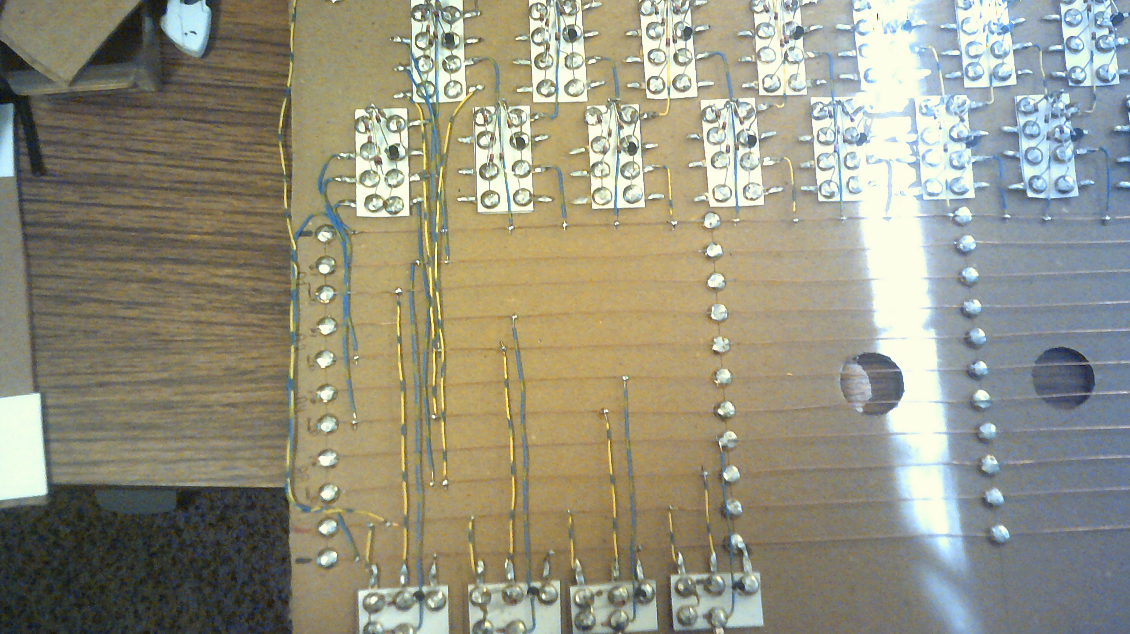
Update April 30, 2018 - Here is the progress today. The first image shows the power wiring.This next image shows how the first two 4 input nand gates are wired to the address buss.
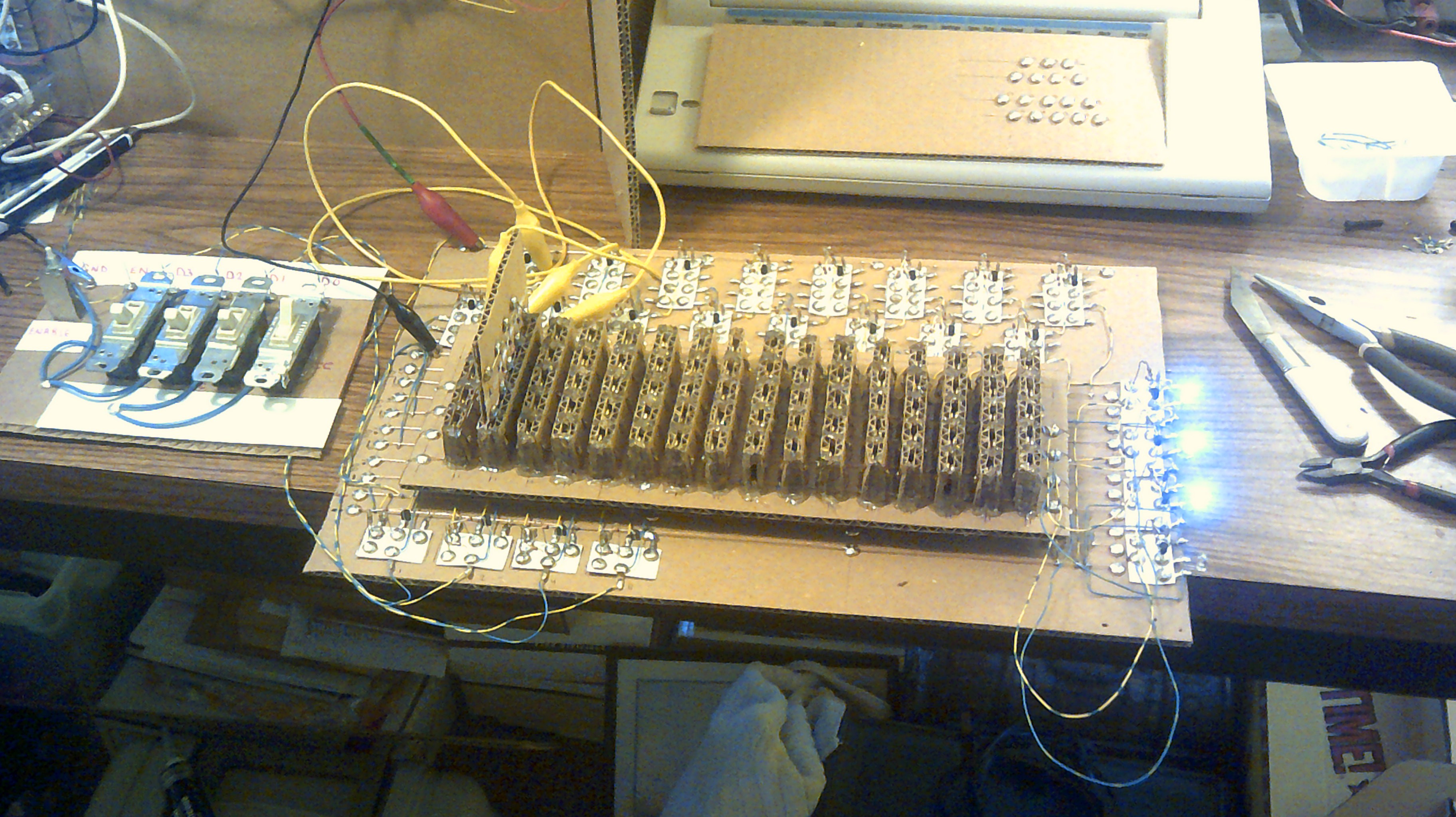
This shows the unit being tested. the simulated address switches are set for address 0001 and a rom instruction card with the value of 0111 is inserted into the second slot. The output leds indicate 0111. So far, so good :-)
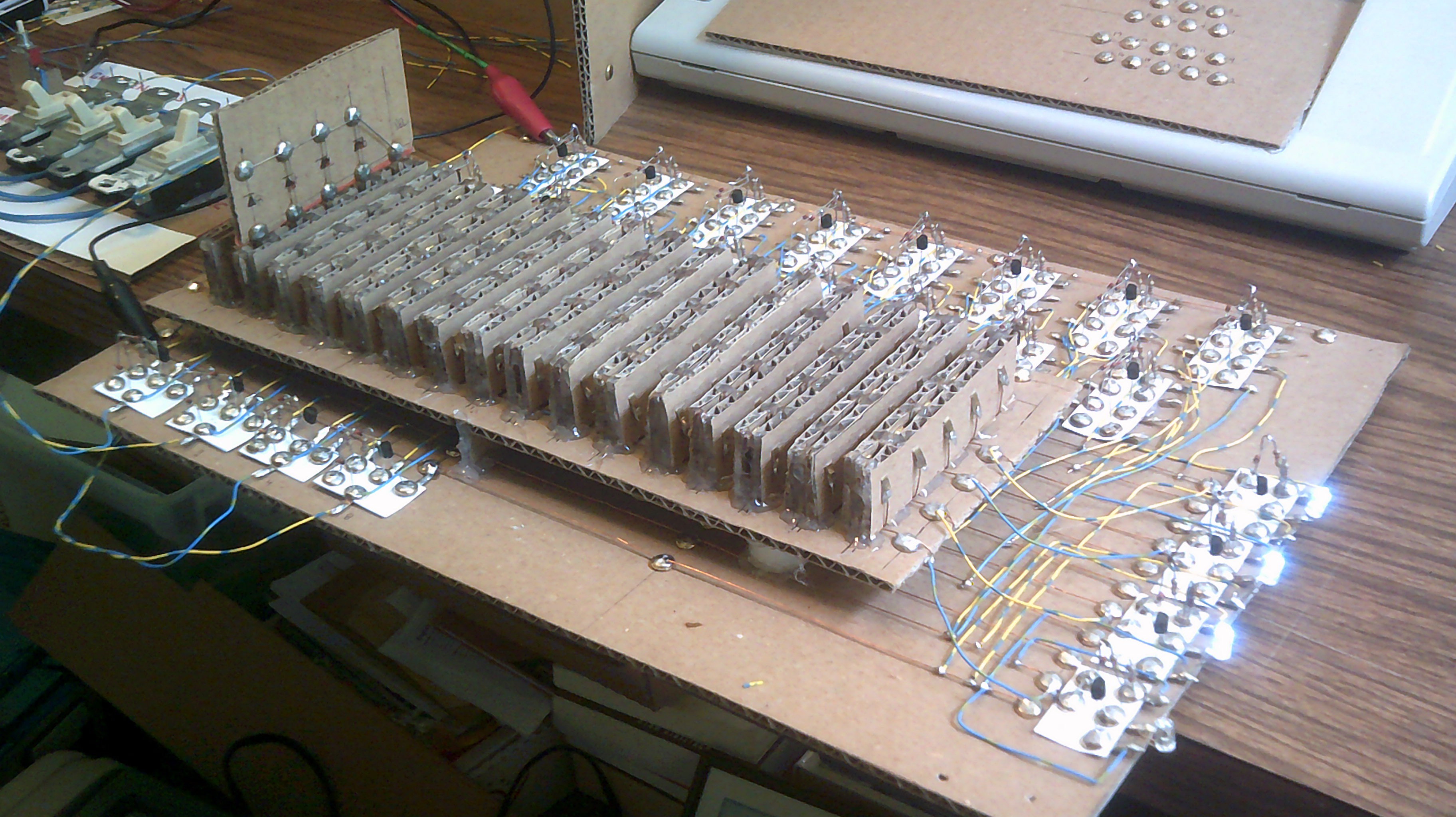
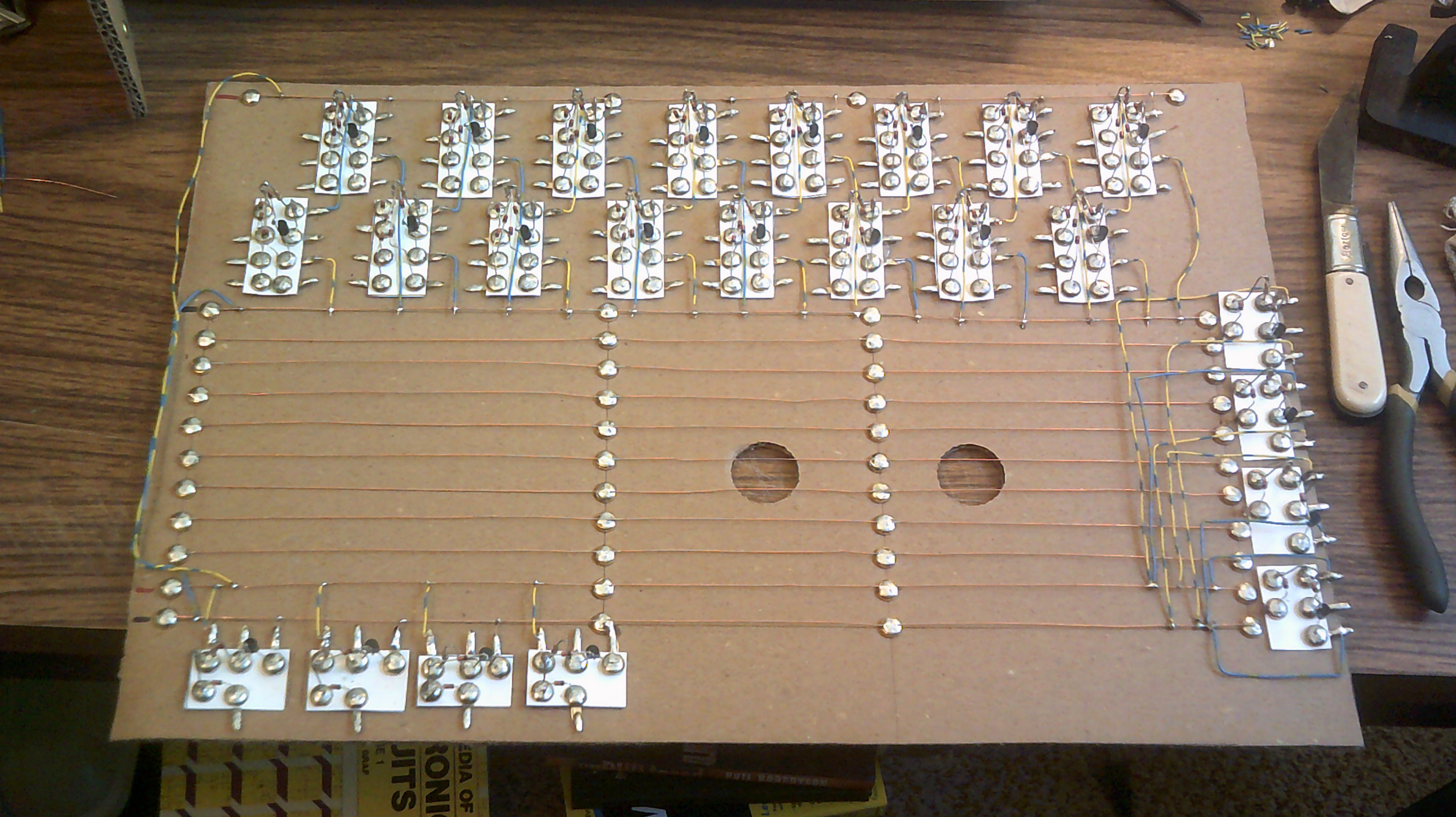
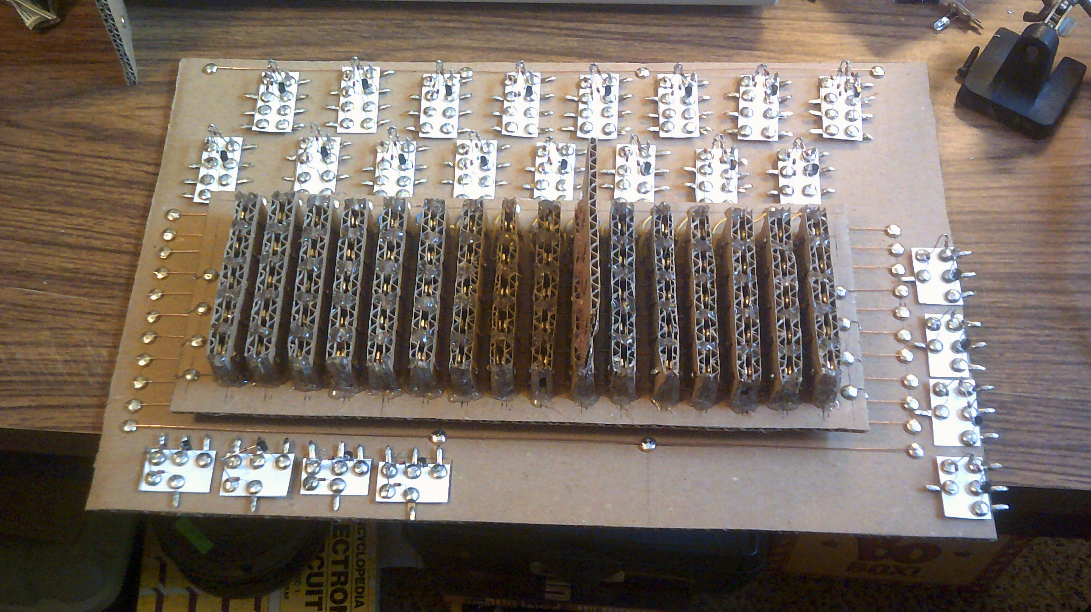
Update April 29, 2018 - I have set up the logic gates and ready to do some serious wiring. The four gates on the lower left is the address input from the PC. The 16 Nands at the top decodes the address and selects the required instruction to be read. The four gates on the right side is the instruction output to be sent to the CU.
Update April 17, 2018 - After the usual delays I am getting back to wiring up the logic gates and get back on track with the Brain Warp instructions.
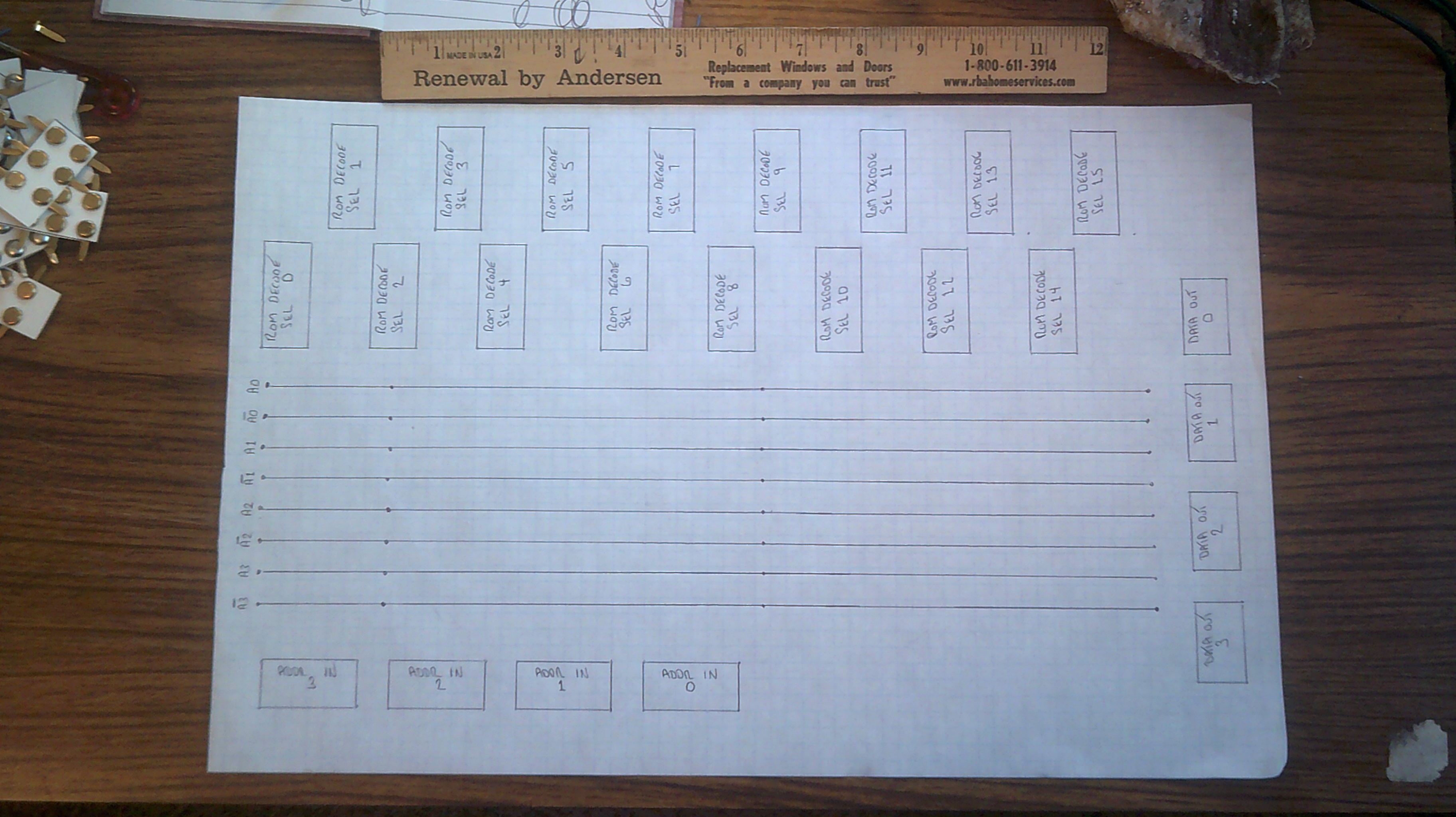
Starting to layout the construction and wiring for the logic board that will read the program ROM cards. Just like all other wiring on IO, this will be a large board...
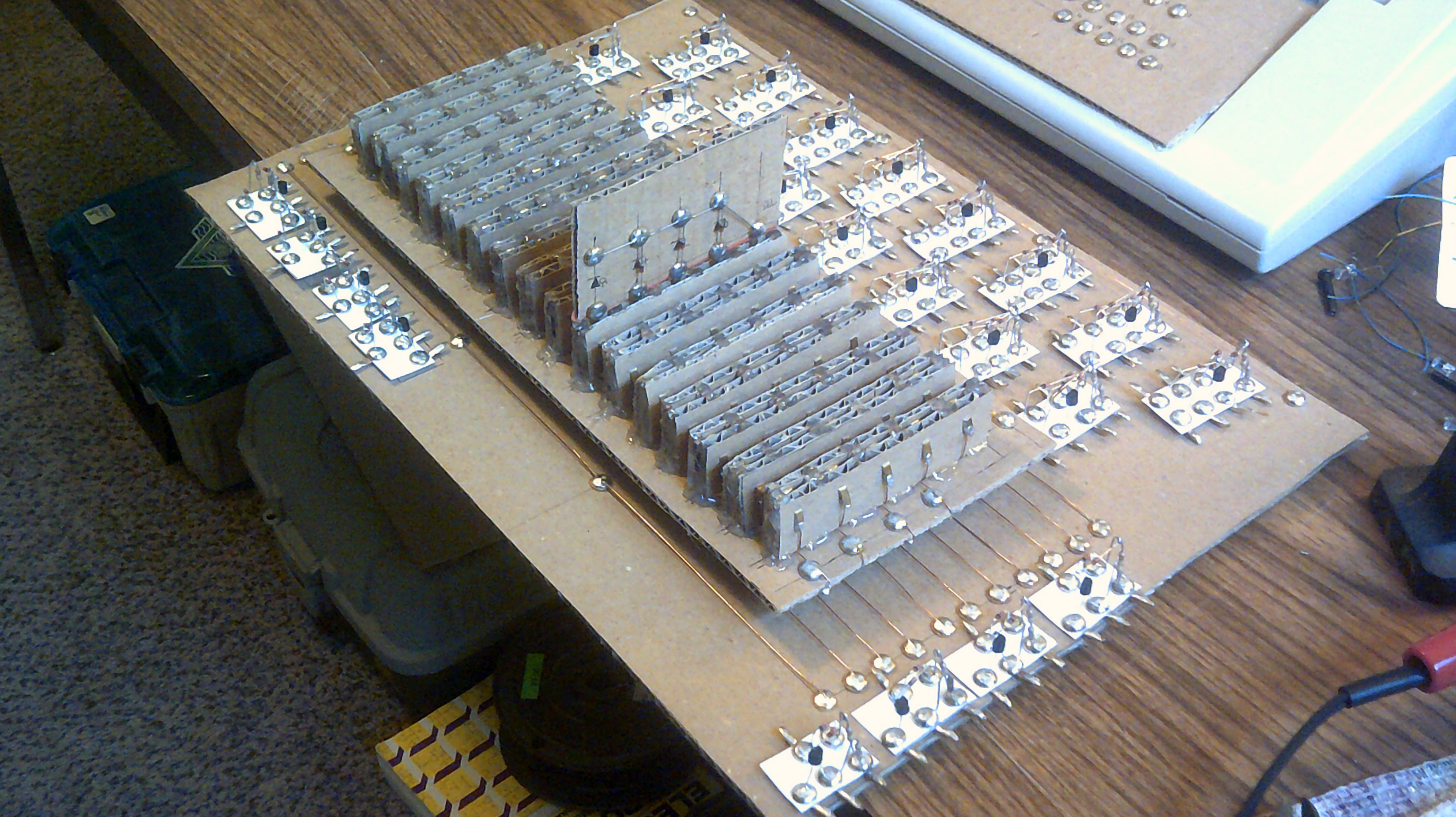
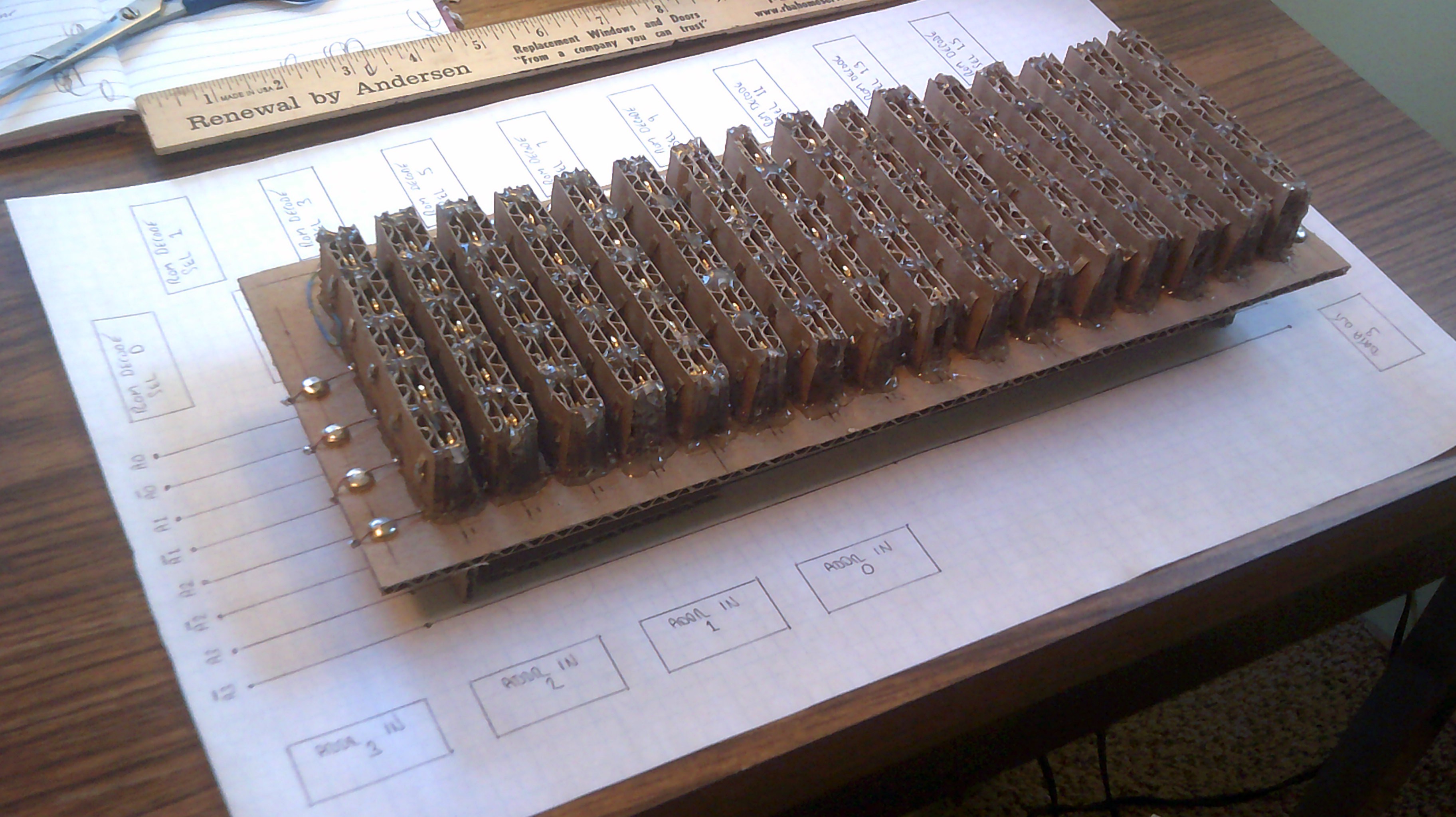
The ROM back plane will mount above the logic circuits...
The Cardboard Computer - IO is my name
My goal is a 4-bit CPU using recycled cardboard substrate and Diode Transistor Logic. This is an educational platform for me.
 Dr. Cockroach