Dr. Cockroach
-
April 21, 2017 - Revised instruction card
04/21/2017 at 19:38 • 2 comments![]()
I have found out that after several cards were constructed that the cards were too stiff and warped out of shape enough to not give me a correct read every time. I have gone back to a simple design that gives a view of what is going on with the circuit and the magnet serves as both a graphic presentation of the instruction but also serves as a grip for placing and removing the card from the reader panel. I still need to wire the rest of the panel.
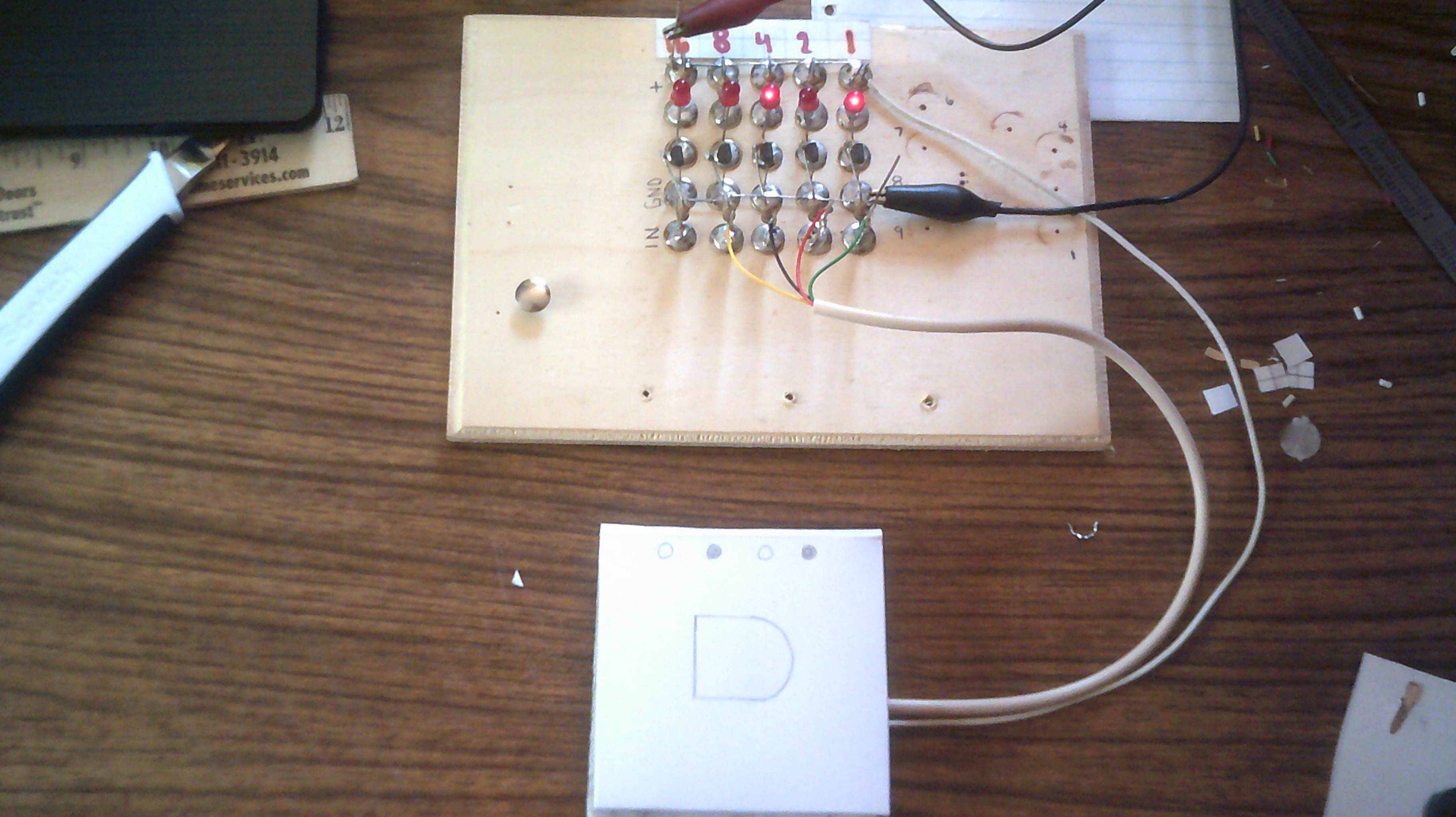
The Instruction set reading left to right , top bottom
code - instruction
1 - Subtract one from the current cell value
2 - Add one to the current cell value
3 - Move pointer back one position
4 - Move pointer forward one position
5 - Begin while loop
6 - Return loop until current cell = zero
7 - Input value to current cell
8 - Output value from current cell
All cell values are set to zero at the start of a program run.
-
April 16, 2017 - Instruction card updated
04/16/2017 at 08:31 • 0 commentsI have updated the instruction card buy reducing the magnets down to two. One for the reader pad and the other for the card. I have also added foil to the reader pad contacts and now have very good reliable contact between card and pad. I am also enclosing the card using the #Origaime (Cardware-bis) method.
![]()
Ceramic magnets are now going to be used as the pull is now enough to provide reliable contact.
![]()
![]()
-
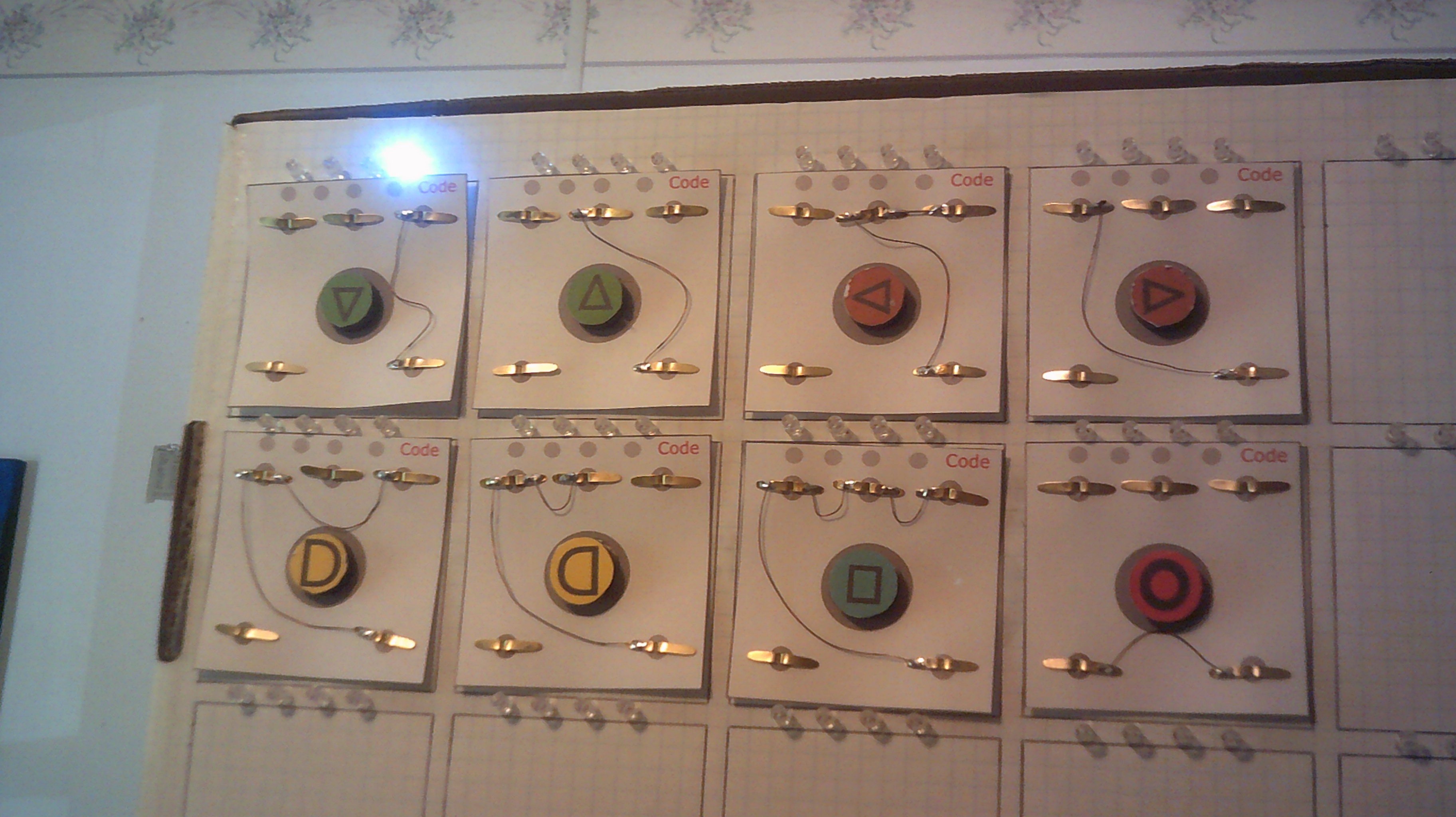
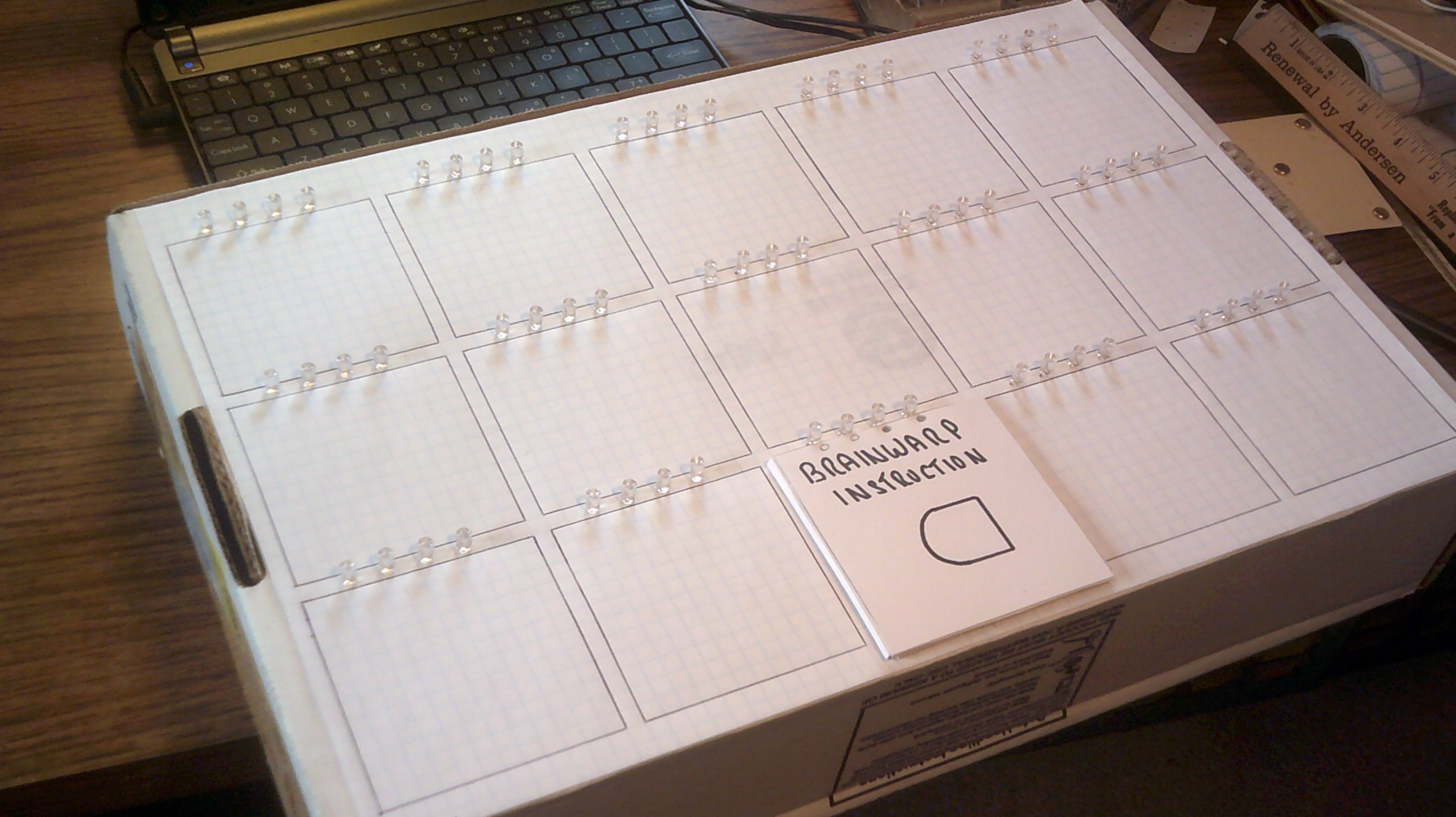
April 12, 2017 - Brainwarp, The program entry panel
04/13/2017 at 00:19 • 7 commentsThis is a scale mock-up of the program entry panel known as Brainwarp. A very RISC instruction set based on Brain*uck is used with some notable changes. There are eight instructions and program cards will be used with each card setup for one instruction.
![]()
![]()
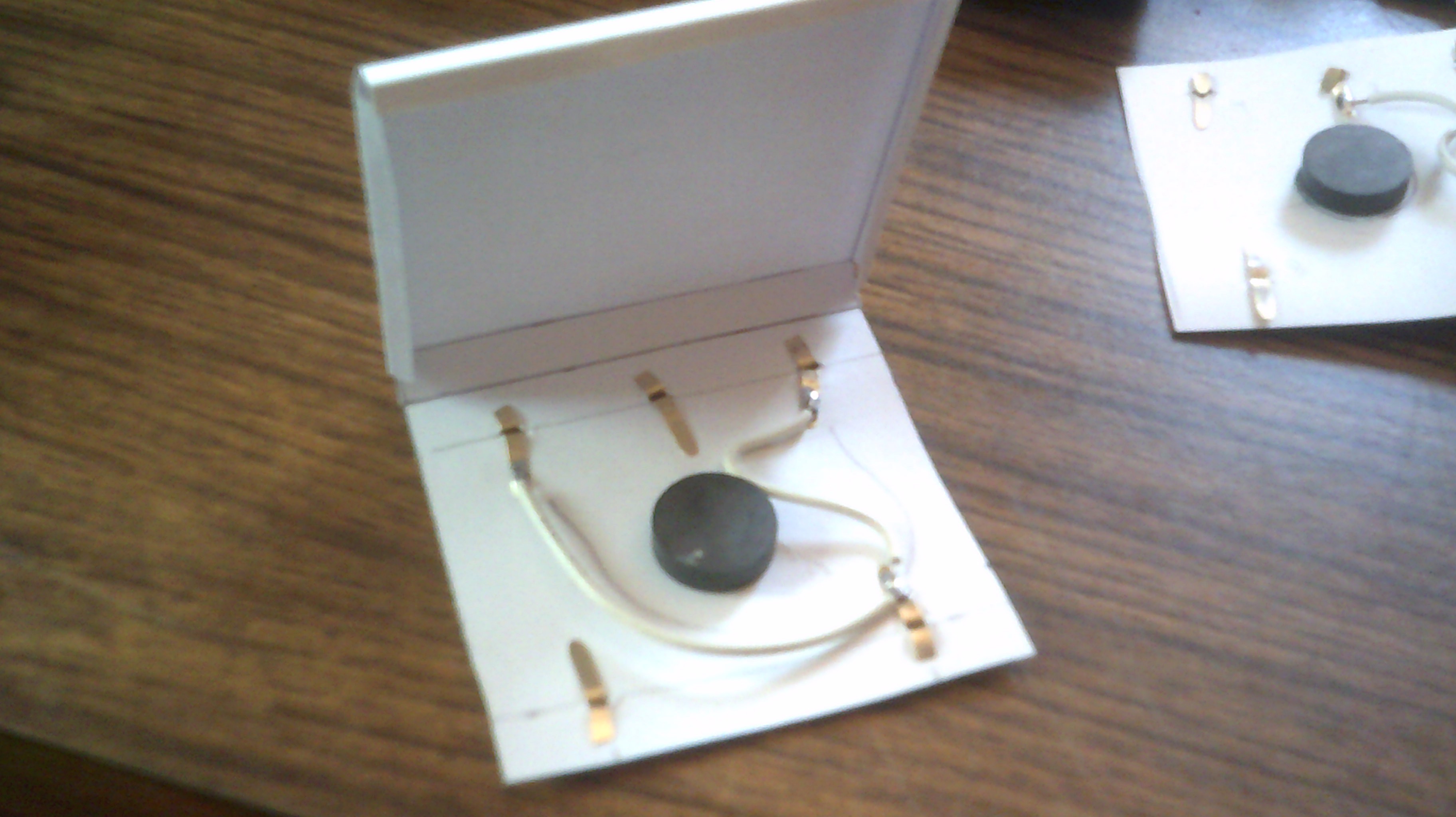
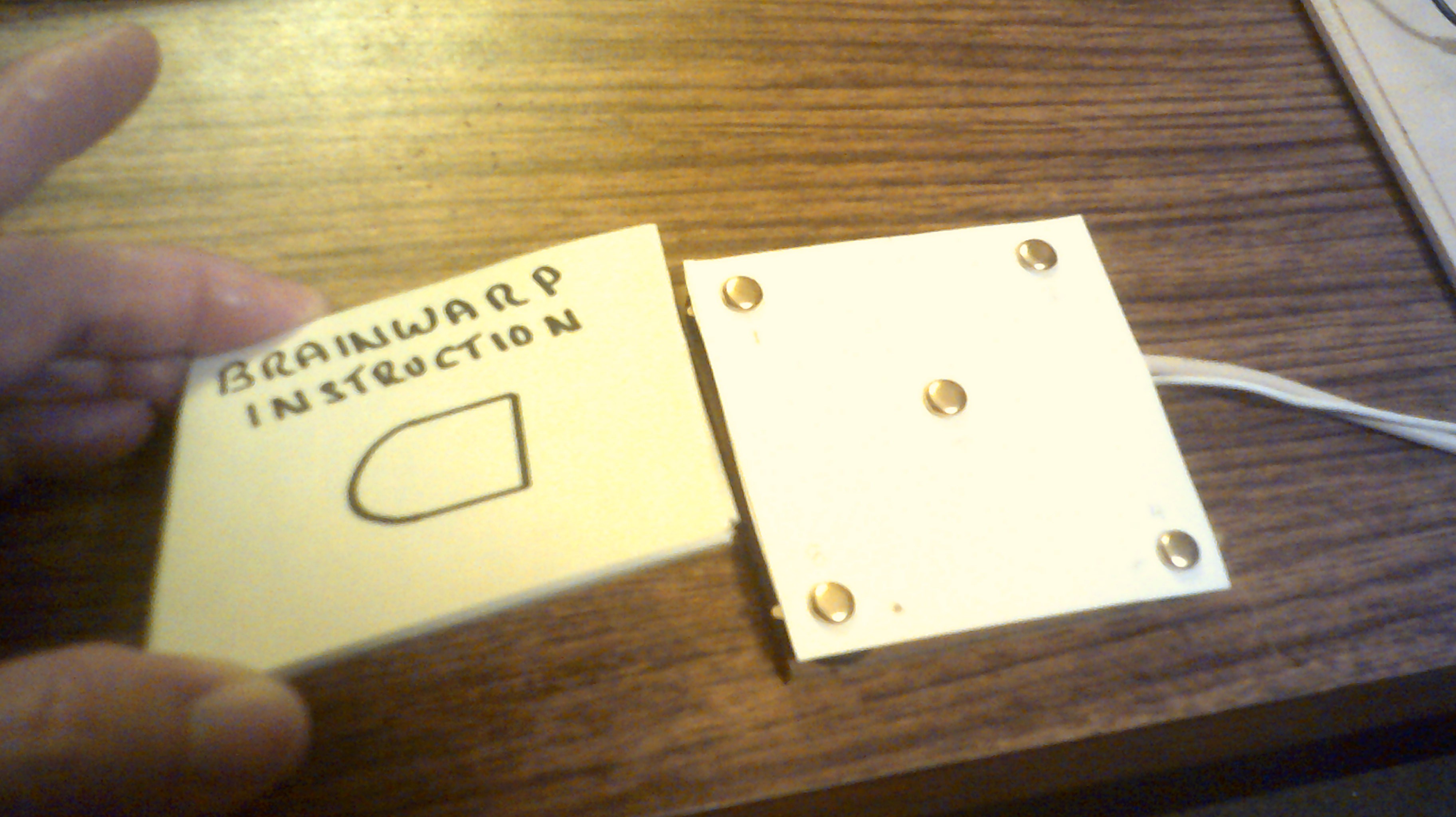
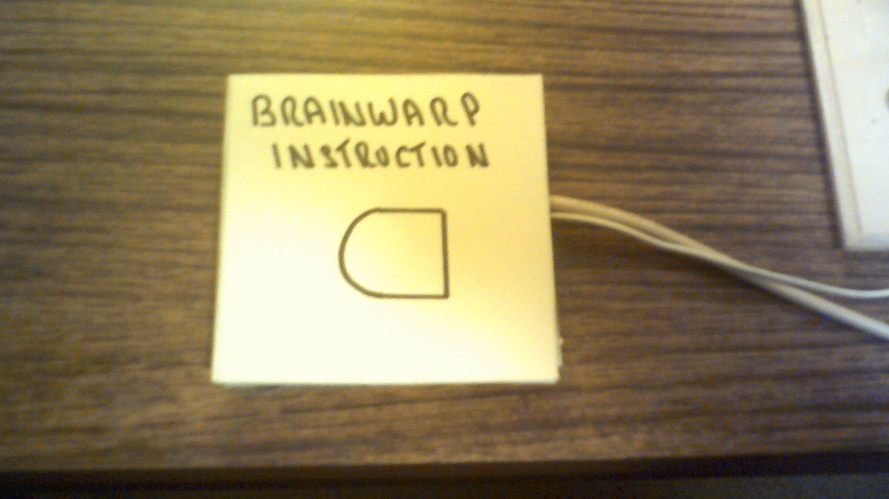
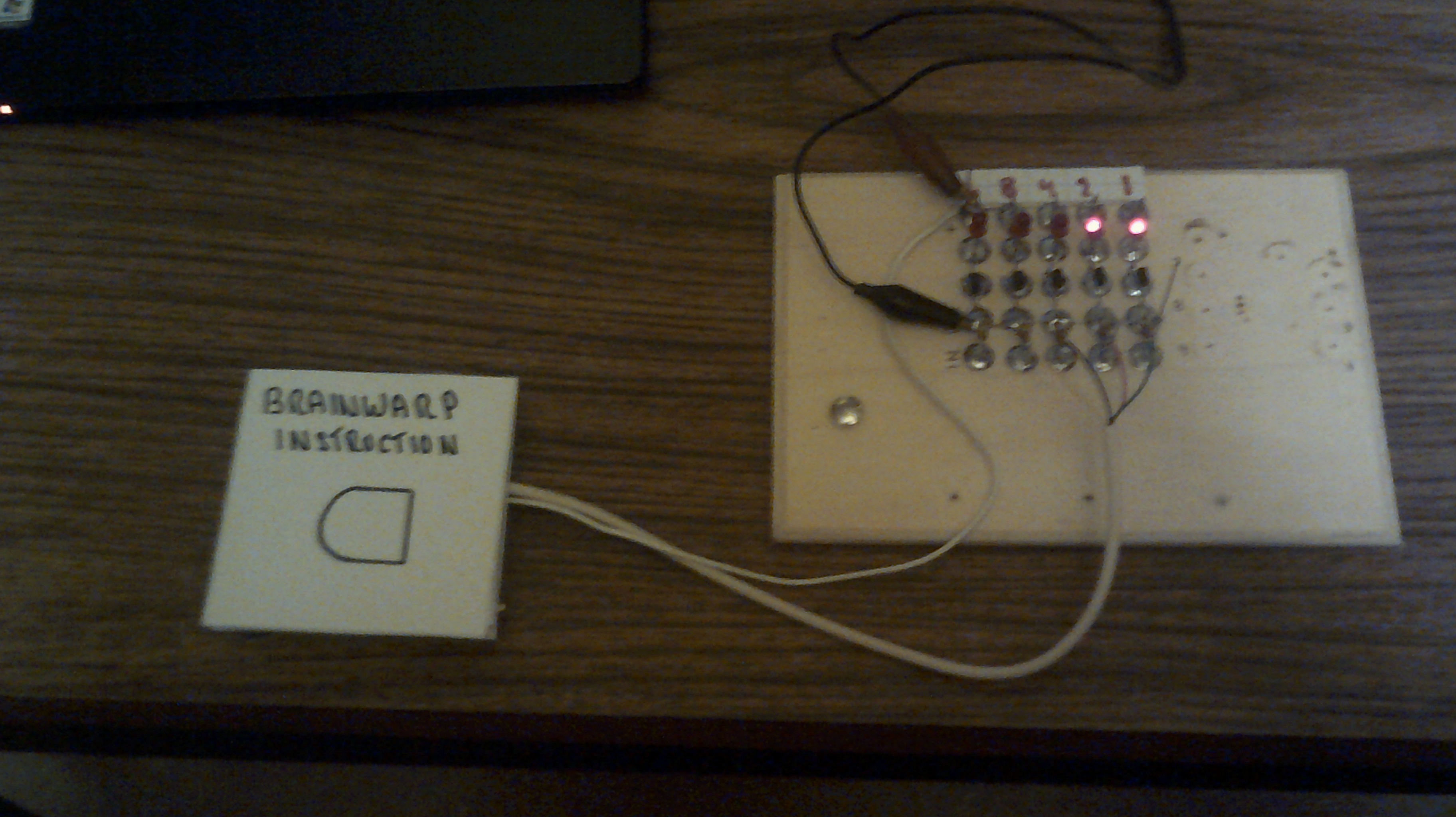
Below is a working example of how the card works.
![]()
The card with the desired instruction is placed onto the program pad.
![]()
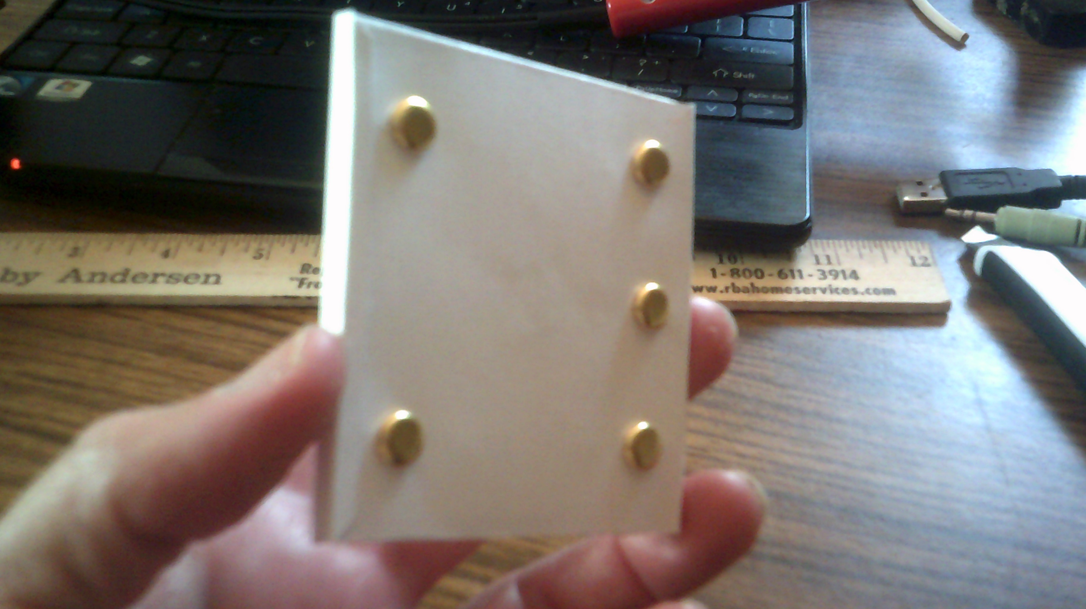
And in this case, the code for this instruction is 3
![]()
-
April 9, 2017 - Parts update and something new
04/10/2017 at 00:03 • 1 commentI have just received over 1000 1n4148 diodes and now work on IO can begin once again. I have been brain storming with the team and I have decided on a RISC instruction set for this project. However, I am not yet ready to reveal the instructions and the method of program data entry. But I will say that this is going to be a very novel way to program IO and to read the instructions. I do not want to tip my hand on this and spoil the surprise for everyone :-)
-
March 29, 2017 - A late welcome to Yann Guidon
03/29/2017 at 23:16 • 2 commentsI am a bit late but I want to welcome the newest member of the Cardboard Computer team, Yann Guidon.
Yann has been a helpful supporter of this project from the first days of my joining HaD. Yann has donated to the
project 500 transistors to help further the build. Thank you Yann :-)
-
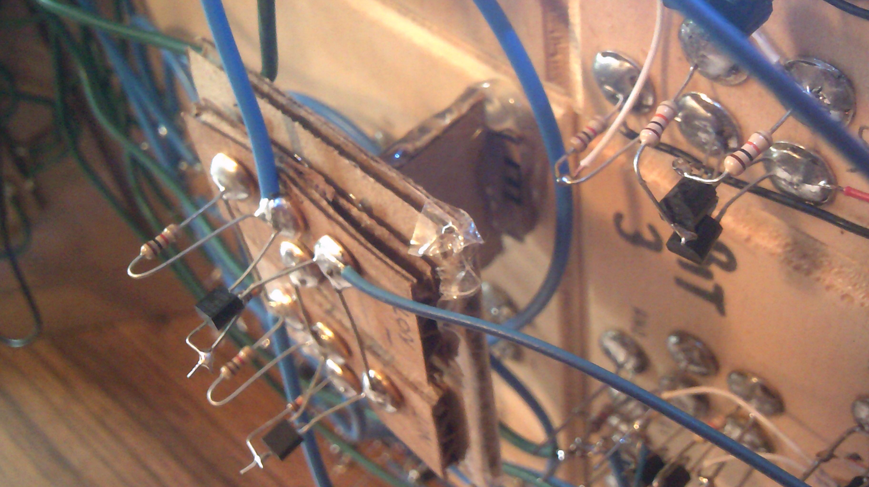
March 2, 2017 - Solving a issue with the ALU
03/02/2017 at 20:01 • 2 commentsI had noticed that once I had the ALU connected to other parts of IO, that the logic levels were not all high enough to light up the led's. The big problem was when all four A inputs ( or B ) were set high and then set the first B ( or A ) input high then the only output should have been just the final 16 carry bit. However this was not the case and when I measured the voltage I found the high logic was down to about 2 volts. Way too low. I decided to insert a non inverting buffer between the third bit carry out and the fourth bit carry in. This raised the carry logic high level back to near rail voltage and all combinations of adder/ALU inputs produces the expected outputs. I had to create a cardboard support platform for the added circuit.
![]()
-
February 25, 2017 - Cardware is now here
02/26/2017 at 00:43 • 0 commentsTook time off today from IO to work on a project named #Cardware with HexHammer
If anyone has an interest in DIY robotics then this is a project that needs following. Lots of neat things are going into it so please follow along with this adventure.
![]()
-
February 14, 2017 - The Cardboard Computer has a name
02/15/2017 at 01:00 • 2 commentsThe Cardboard Computer has been given a name. Meet IO which stands for Inside Out. Jez @HexHammer and I had been talking about our projects and such and the term inside out from Pink Floyd was mentioned. That was the spark and rest might be history. What better name than for something that would normally be in a box or enclosure to now be on the outside........
-
February 13, 2017 - Converting ALU input levels
02/14/2017 at 01:46 • 2 commentsSpent some time today wiring up a circuit to convert the lower 5 volt logic 1's to 12 volts. I am using just a basic non-inverting buffer using two not gates for each input of the ALU. So far I have one board that takes care of the A inputs. Next I will wire up the same board again for the B inputs. The photos below show the ALU and the newer level converter board. I will be adding some leds as power indicators.
![]()
![]()
-
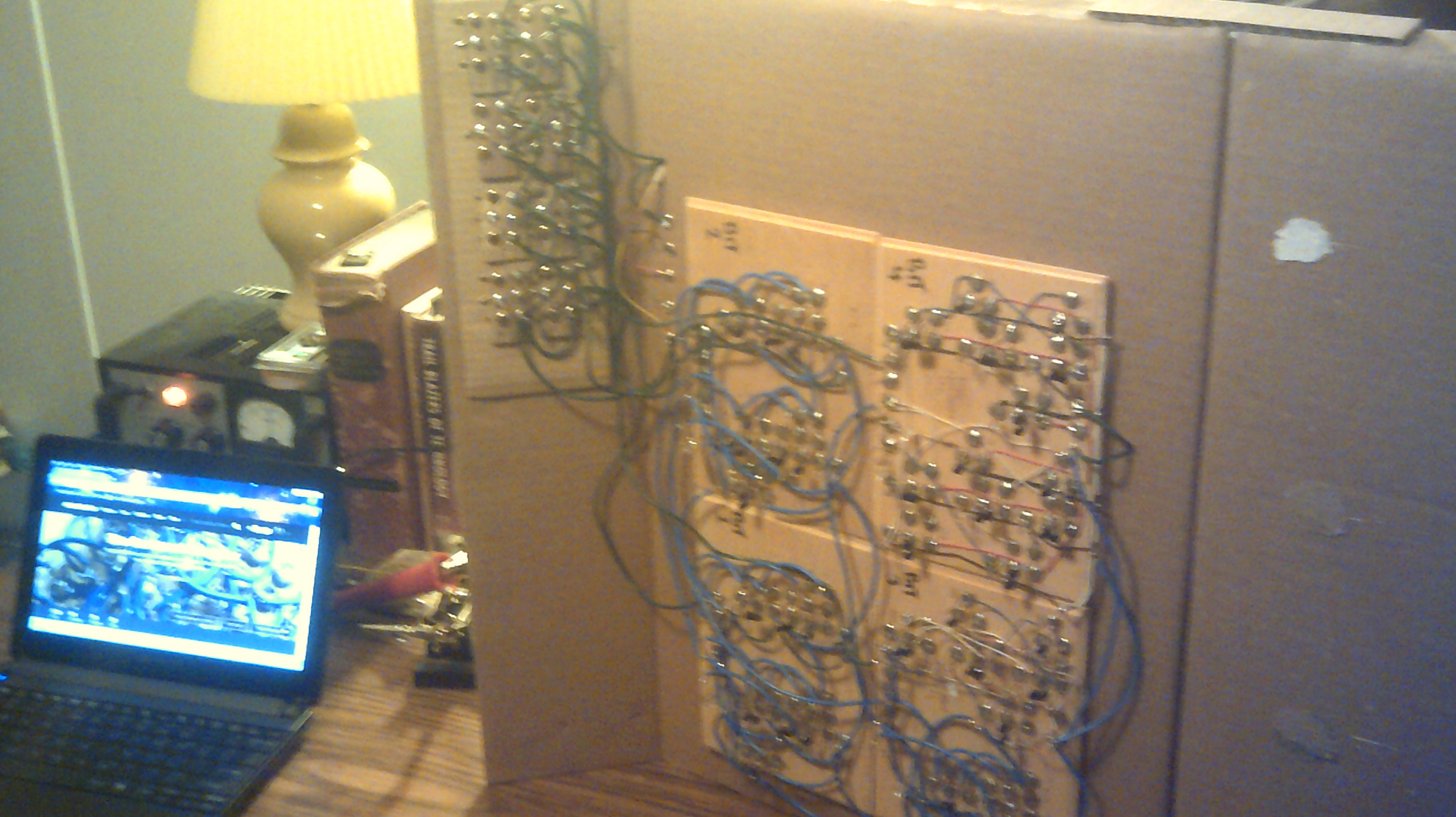
February 12, 2017 - Logic level voltage issues
02/13/2017 at 00:08 • 0 commentsI have used today to get my old 4-bit adder working with the rest of this computer. I am having some logic level voltage issues between the adder and the rest. The adder was designed and wired a year ago as a stand alone project to operate at 9 to 12 volts and most of the rest of this computer operates at 5 volts. I have been able to get the adder output to latch into my new register. However, The lower level outputs from the other stages are not high enough for the adder/alu inputs. I will try using buffers at the alu inputs to boost to the higher level voltage that the alu is looking for. It's either that or rebuild the alu and I really do not want to do that.
The Cardboard Computer - IO is my name
My goal is a 4-bit CPU using recycled cardboard substrate and Diode Transistor Logic. This is an educational platform for me.