Dr. Cockroach
-
December 31, 2016 - End of an interesting year
12/31/2016 at 12:18 • 0 comments2016 will be remembered as a very challenging one for me, in electronics that is. Back at the beginning of this year I became interested in a 4-bit full adder circuit and built it. It worked and I was hooked on transistor logic. I then embarked on the quest to build a 4-bit processor and learn how it worked down to each component. Right now I realize that I have a loooooooong way to go before I have a finished project but I have been working on the separate sections and learning a great deal from all this.
I want to thank all the new friends that I have already made here on Hackaday.io and to you all I truly wish everyone a happy new year for 2017.
-
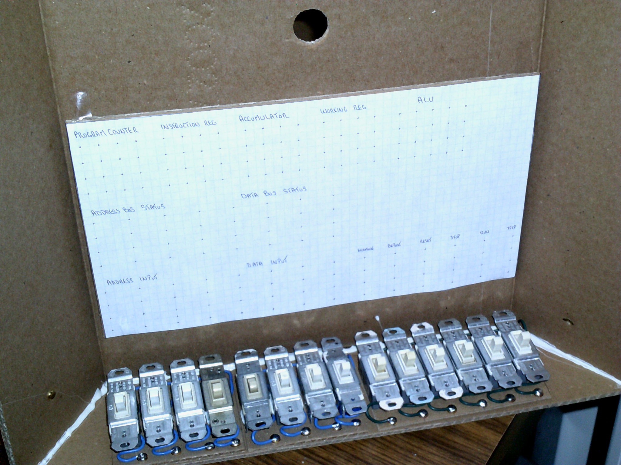
LED display panel
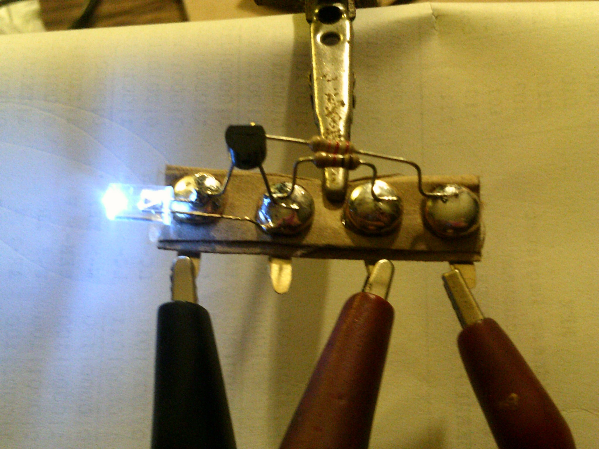
12/31/2016 at 10:42 • 13 commentsI am working on the display panel and here is a little cardboard led driver strip using a pnp 2n3906 transistor.
The display panel will have a lot of these.
From right to left - input , +5 , nc , gnd
Base resistor 22k and emitter resistor 1k in this tryout.
Current draw with led on/transistor off = 2ma and with led off and transistor on = 2.5ma more or less so current is always flowing. Could be a better circuit but it's simple and it gets the job done.
![]()
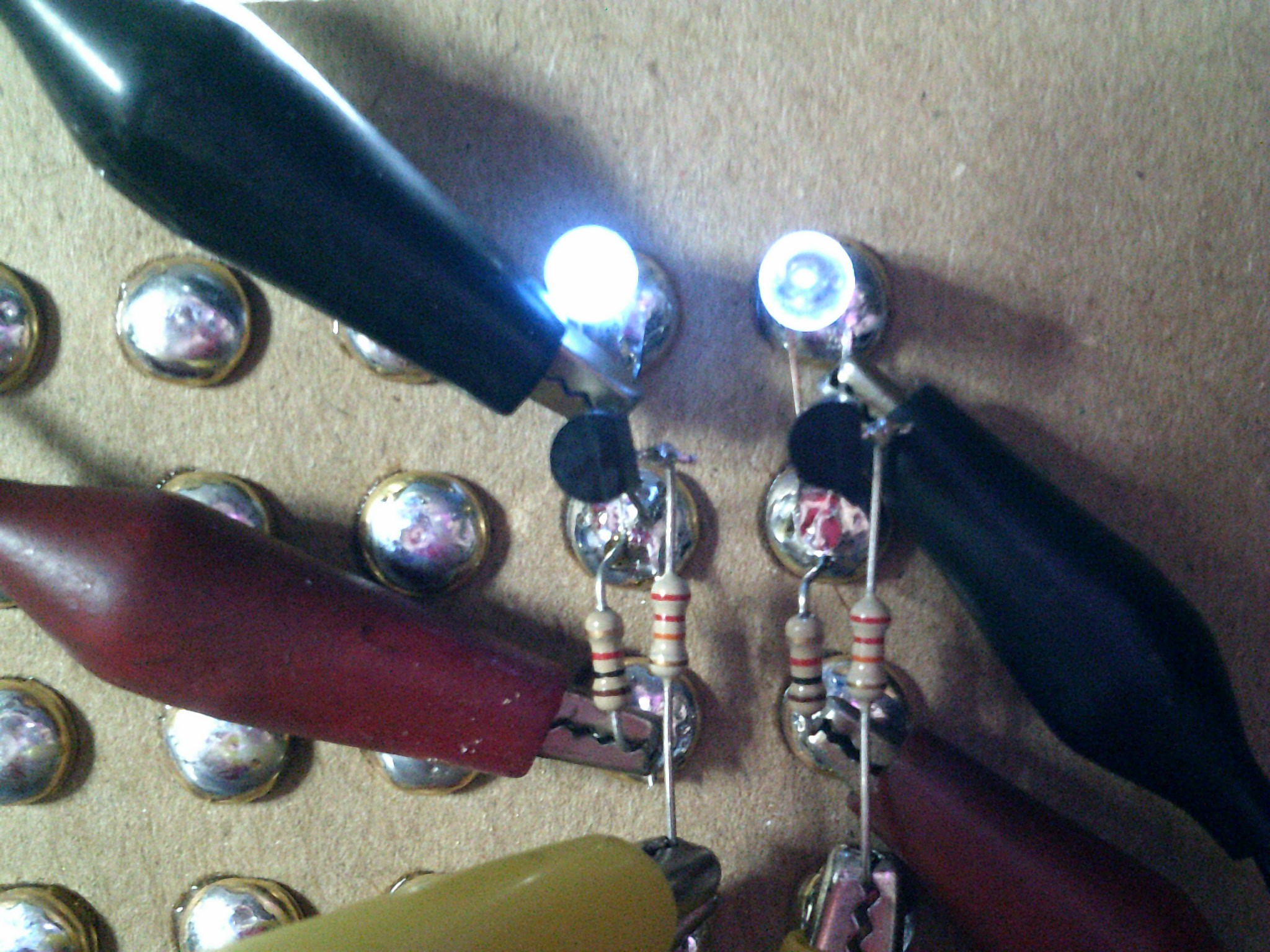
January 5, 2017 - This better shows how I improved the look of the led by sanding out the concave top surface. The led on the right is with the concave feature and on the left after sanding.
![]()
![]()
January 5, 2017 - Starting to layout the display panel. I am leaving a little open space for any additions.
![]()
Cardboard base is cut to size and taped up to show what I have in mind.
![]()
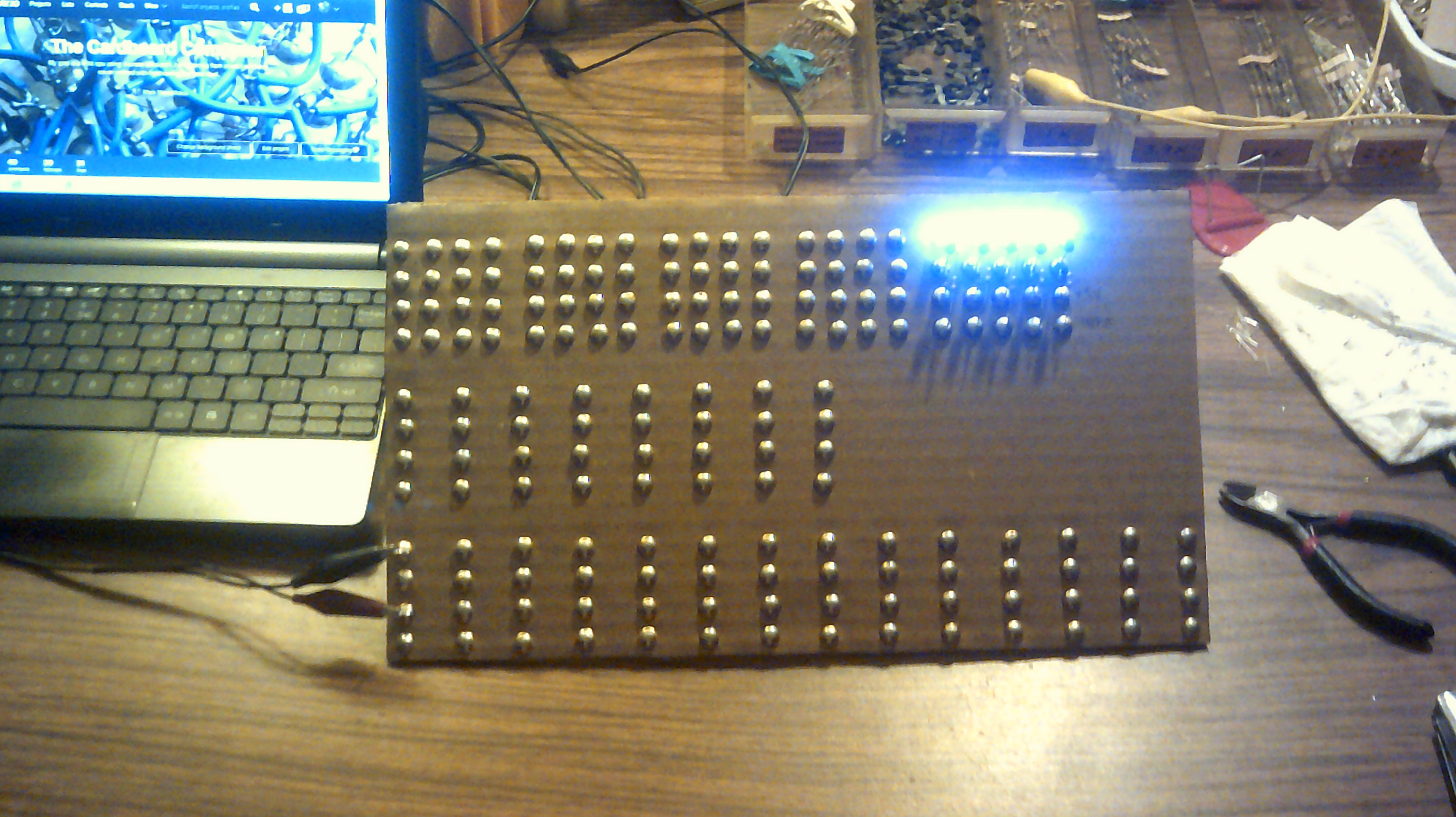
Holly brightness Batman - If all 43 leds light up at one time then I just might go blind :-) Of course that should not happen, but then again...
![]()
Well, the top register row of leds are in place. If this computer fails then I can at least use this panel as a bathroom light. https://hackaday.io/hacker/140533-ted-yapo Thanks for posting Wrencher :-)
![]()
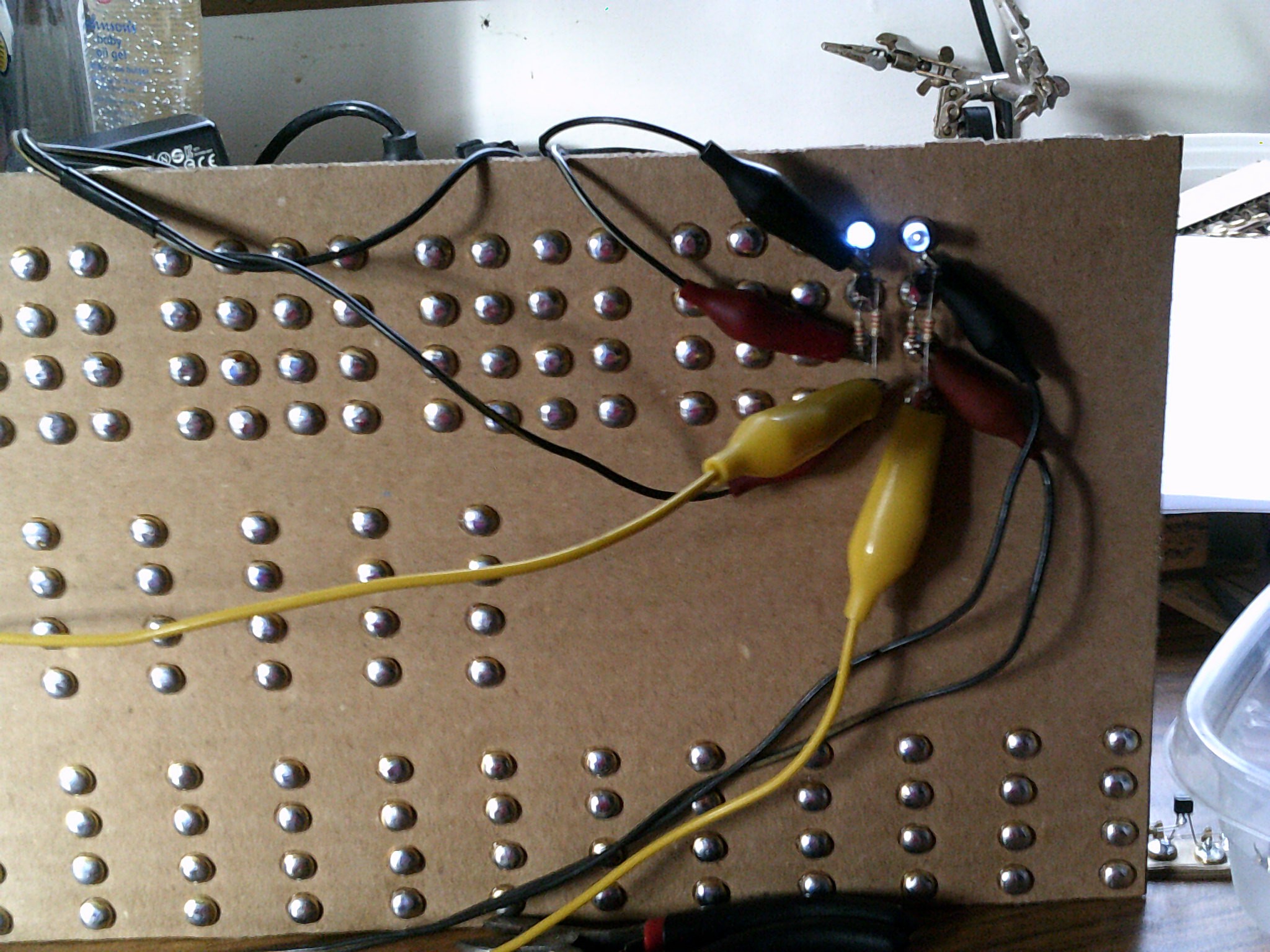
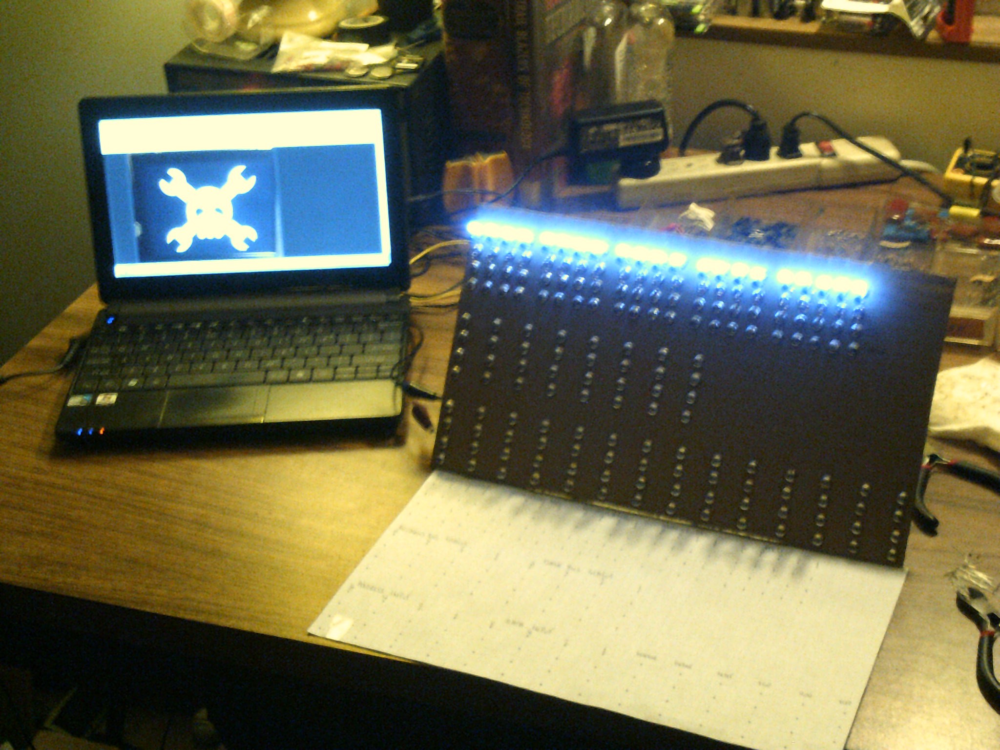
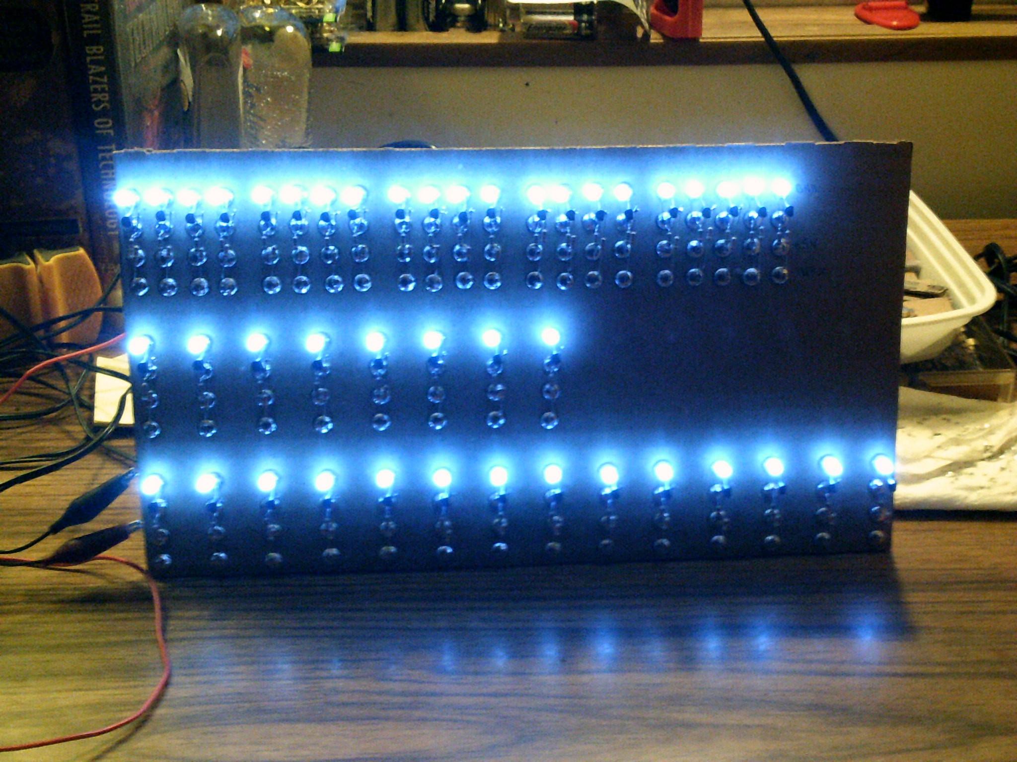
01/09/17 - So far so good. All leds light up and when the inputs go to ground the transistors shunt as needed.
![]()
-
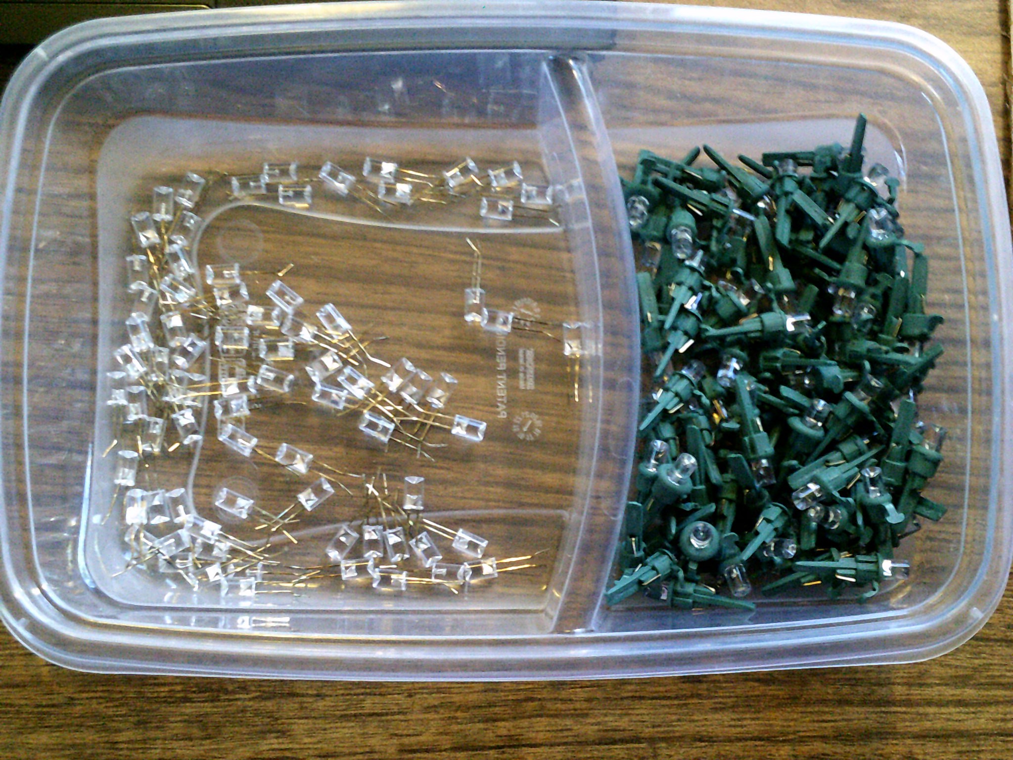
12/29/2016 - Really cheap LED's
12/30/2016 at 14:18 • 4 commentsFound a string of Christmas led lights at a local thrift store for 1 dollar. There are about 200 led's and it looks like they operate around 3.5 volts and 3.75 ma each. These should be perfect for the output display section.
![]()
-
1 to 4 demultiplexer
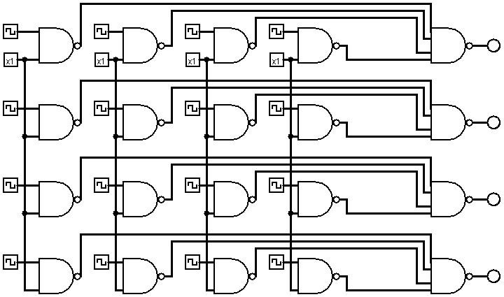
12/26/2016 at 09:25 • 0 commentsDecember 26, 2016 - just started playing with a demultiplexer circuit on Logisim last night so here what I have so far. Top inputs are the data bus lines and left side is select inputs. The sim likes it. Each row is output bits to selected registers or whatever. Why not use AND gates? I work better using my standard Nand gate circuit.
![]()
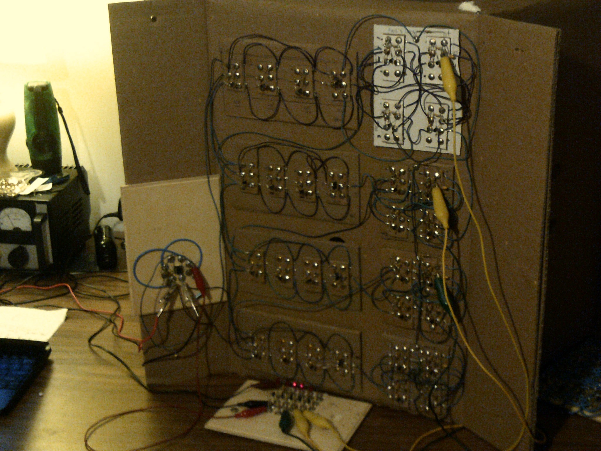
Update 12/31/16 - I have have finished soldering the gate VLC's and about to hot glue them to the base board. I am going to wire only half of the dmux and test it that way and if all is well then wire the second half. The two gates on the left are the select gates and the top row will output to the ALU. I don't know about the second row yet.
![]()
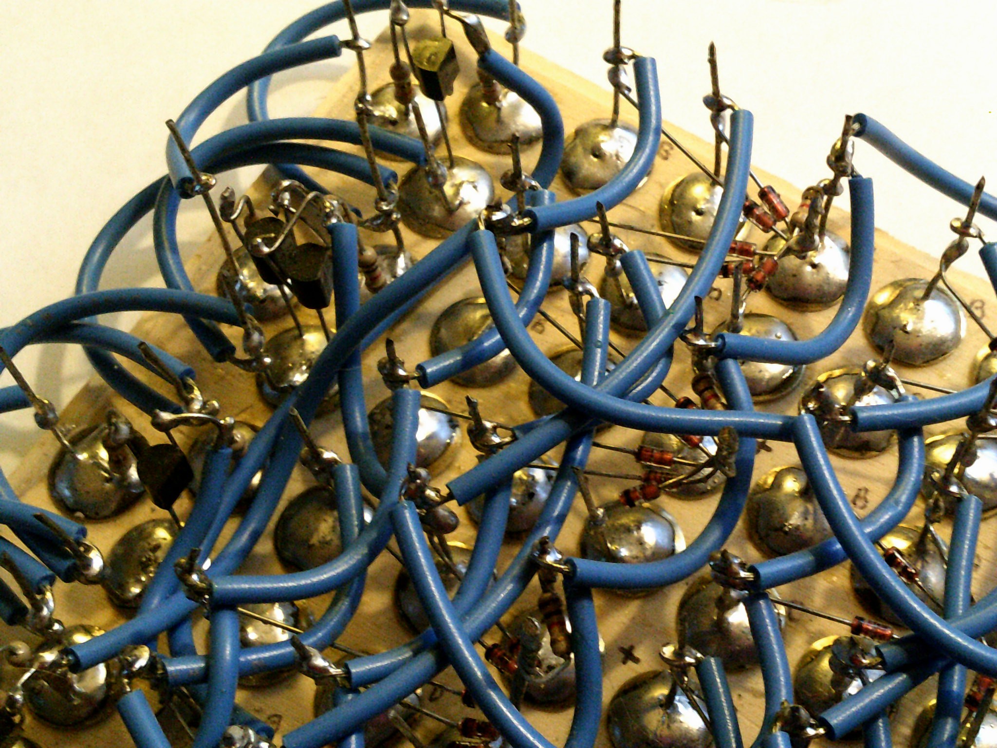
Update 1/1/2017 - Gates are glued down and started the wiring with the positive leads. Yes, this method takes a LOT of time but it is a way for me to relax after a day of cooking.
![]()
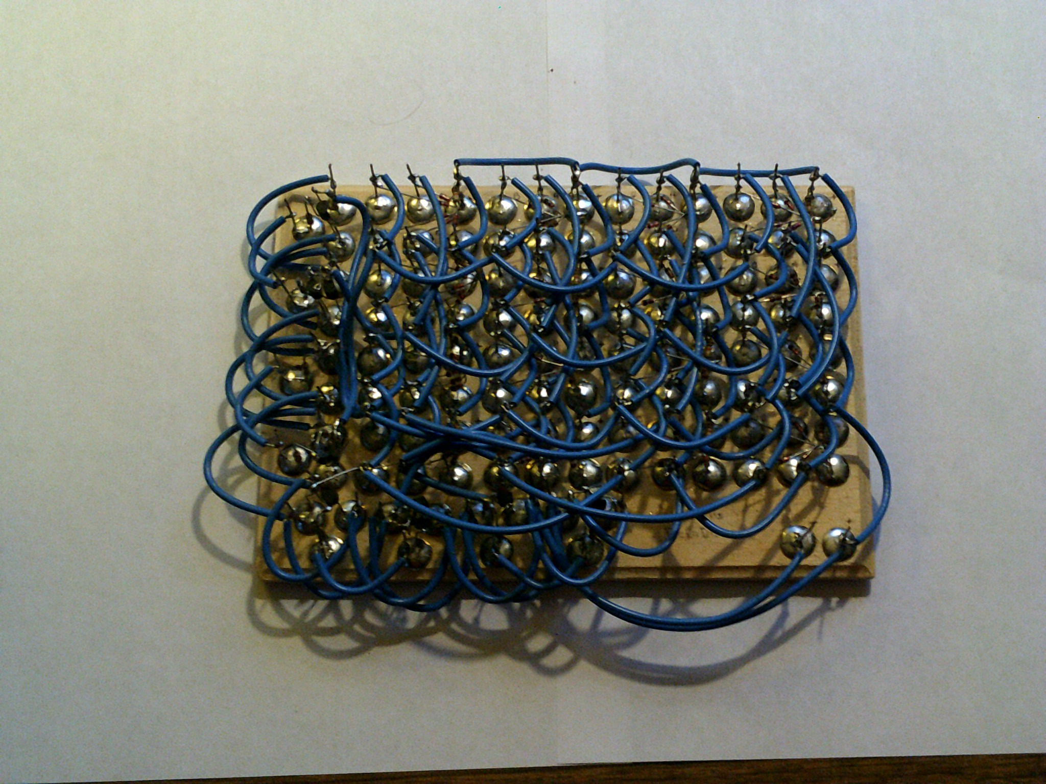
Update 1/2/2017 - The power and ground connections are finished. Now onward with the data wiring.
![]()
Update 1/3/2017 - Ok. this is half of the dmux wired and tested good so far. That's a lot of point to point just for a 1 to 2 unit :-)
![]()
-
4 to 1 multiplexer
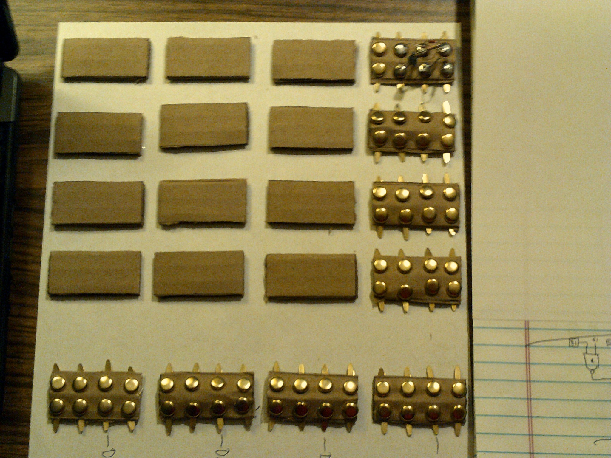
12/25/2016 at 22:46 • 1 commentDecember 25, 2016 - The start of laying out the cardboard logic chips ( might as well call them very large chips or VLC's )
I will be running out of diodes before the end of this and the dmux build but at least I will get started. The logic is very basic and will end up being modified by the time I am finished. Logisim likes the circuit so far.
![]()
![]()
-
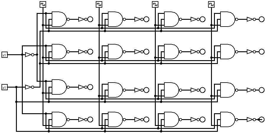
The state machine sequencer
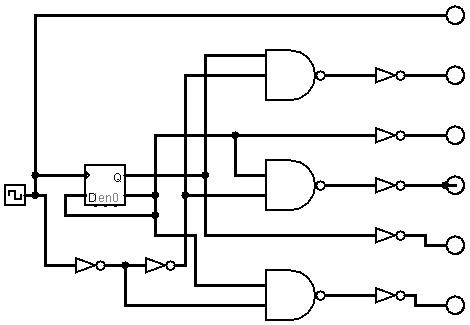
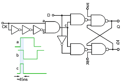
12/22/2016 at 09:48 • 4 commentsI needed to start looking into the FSM part of this project and found a circuit that outputs 5 pulses for every 2 clock pulses ( I cant remember who posted this but if your out there reading then please chime in ). This should help head off any problems with propagation delays along the chain of command. A J-K toggle flip-flop is used to input to the sequencer. ( by the way, I do now have Logisim and Qucs as simulators on my notebook so I can check out the circuits ahead of time. The J-K on the left using nor gates and sequencer on the right using nand gates.
I had a senior moment - The link for the FSM sequencer circuit is Rory Mangles and his TinyTim at http://www.northdownfarm.co.uk/rory/tim/
![]()
![]()
-
Going sequential - The program counter
12/22/2016 at 09:16 • 3 commentsin the summer of 2016 I needed to tackle sequential circuits. So started the real fun ( hair pulling ). On a single flip-flop level I started with the basic R-S to J-K to the D. However when I tried to make these circuits toggle then I began to understand the problems of signal levels, timing and edge vs. level triggering. No matter how many searches on the internet I did, I could not get things to toggle or at least toggle without random errors. I had built a clock using transistors but was not sure of the signal purity ( The only test equipment I have is a analog vom and a transistor tester ). I made the call to allow one chip for this project and that is a trusted 555 timer chip. Did that help, No way. Finally I came across a circuit that converts the square wave output of my clock to a very short pulse. Now my flip-flops started to toggle the way I wanted.
![]()
Below is my program counter connected directly to the clock board on the left. There are four toggle D flip-flops on the right and note the pulser boards to the left of each one. Without them I would not have any hair left.
![]()
-
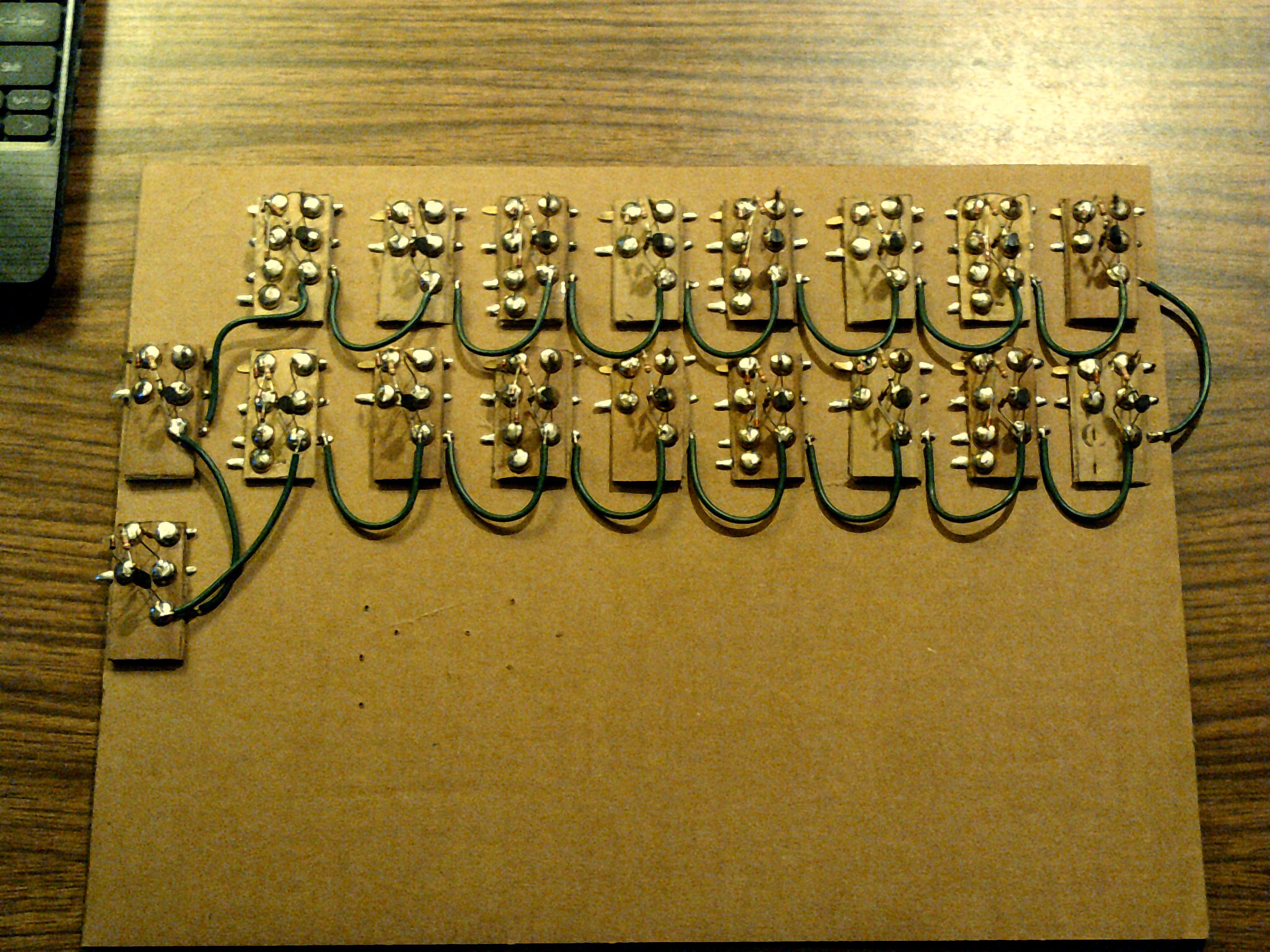
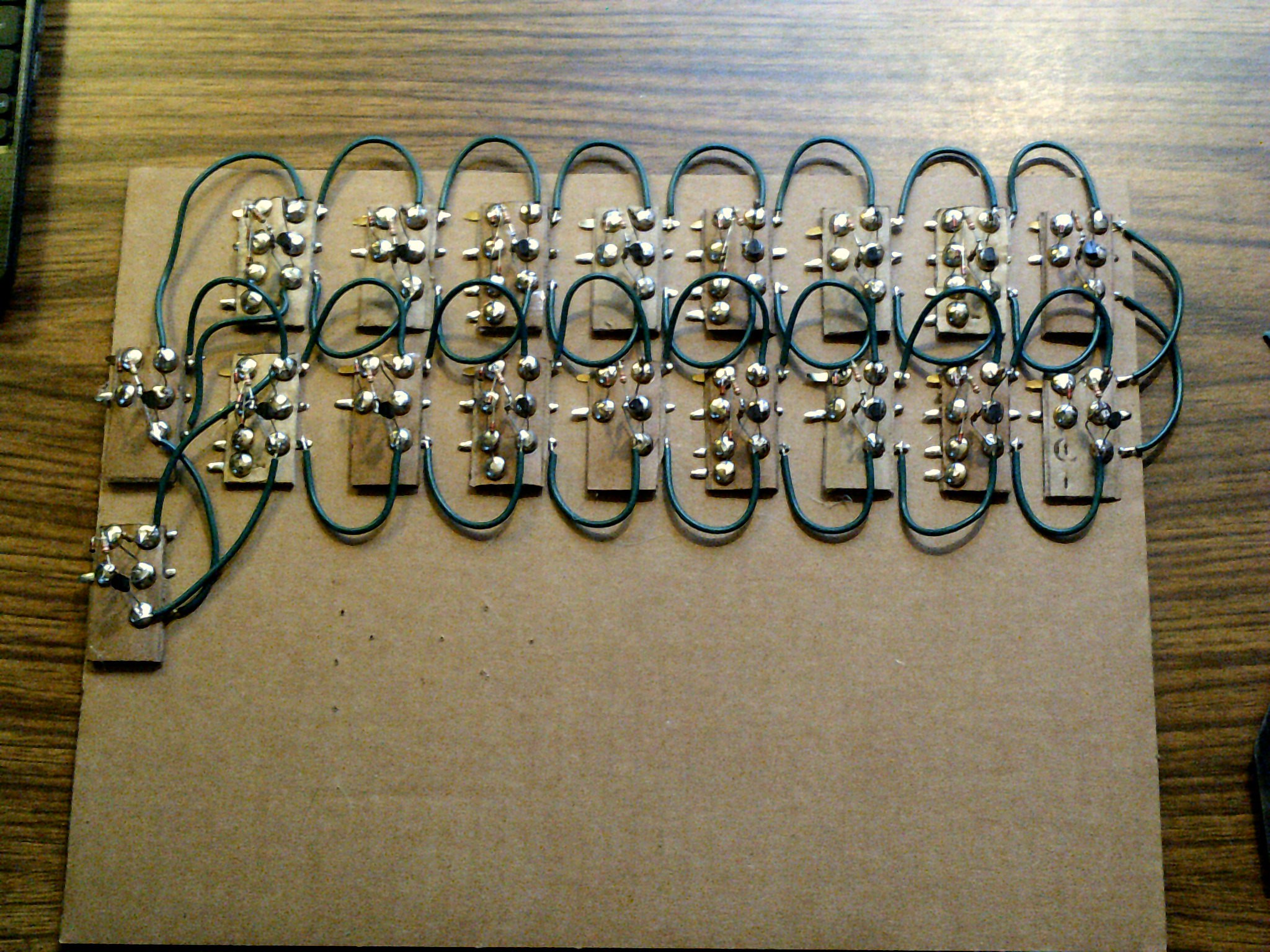
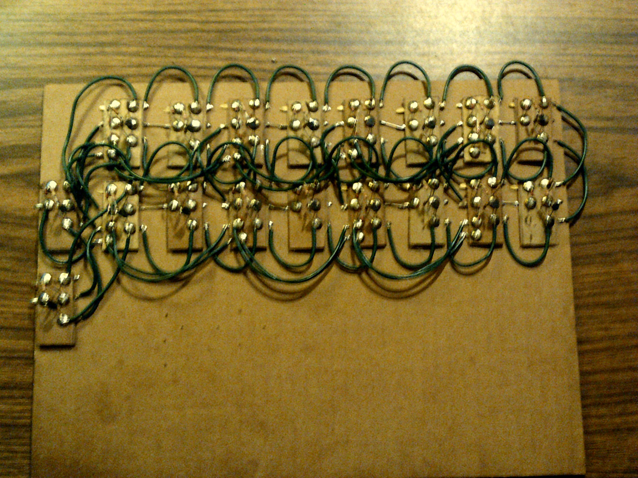
The 4 to 16 line / instruction decoder
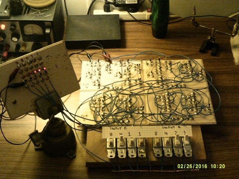
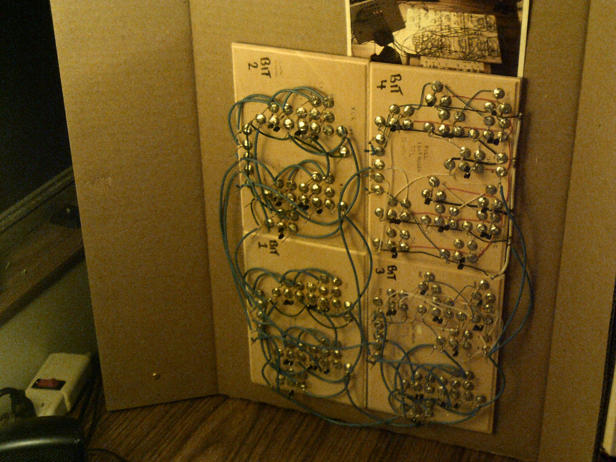
12/22/2016 at 02:00 • 1 commentAfter the adder was finished, I then decided to keep on going and the instruction decoder was next on my hit list. Not much in the number of images except for the final result. the left and bottom edges are the input buffers and inverters using npn transistors. The rest are AND gates using only diodes. This is the last build using thumb tacks on a wood base.
![]()
![]()
![]()
The close wiring on the decoder was a real headache but like the ALU, it worked without errors. ( well, one wrong transistor got mixed in )
-
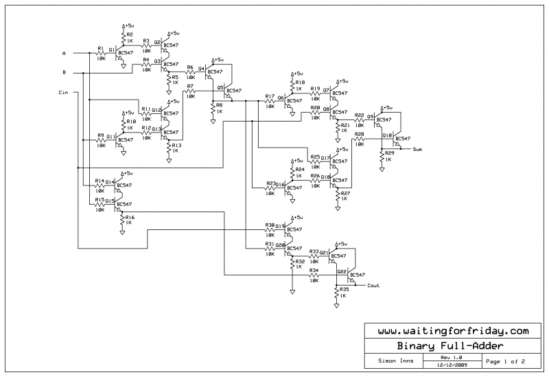
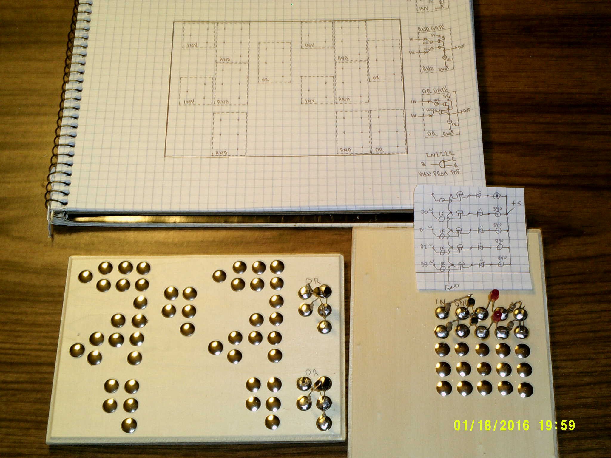
The birth of a notion - The ALU
12/22/2016 at 01:44 • 3 commentsThe cardboard computer started out simply as a 4-bit full adder project that has gotten out of hand. I came across a web site by Simon Inns called waiting for friday. Here are a few pictures of that project that is now the ALU for this project.
![]()
![]()
![]()
![]()
![]()
The Cardboard Computer - IO is my name
My goal is a 4-bit CPU using recycled cardboard substrate and Diode Transistor Logic. This is an educational platform for me.