 CriptasticHacker
Having a proof of concept from the working firmware test, it's time to dive into designing some PCBs.
We need to have a robust and reliable power system. This is a medical device, and something that I rely on heavily, so it can't be prone to errors and issues.
I made the mistake years ago of not allocating enough attention toward a large power PCB. It's time to fix that.
Since this is a battery-powered system, we will be saving power by using a DC-DC converter. The biggest challenge in the system comes with the high-voltage requirement - it utilizes 2x 12V lead acid batteries in series, giving us a max fvoltage of 29.4V(!) if you count the theoretical perfect float voltage charge state. In reality, it's going to be around 27-28V.
For this we need a bulky step-down converter, and nothing fits the bill for affordably and sourcing better than the LM2596 module:
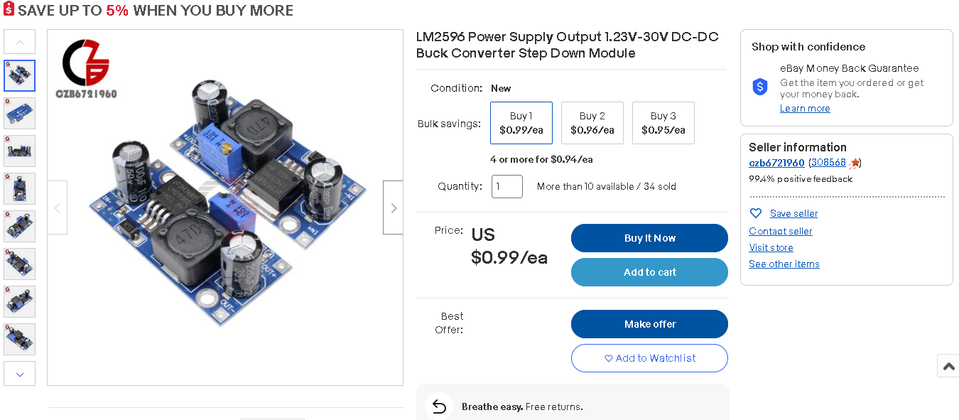
specs (from this link):
Input voltage: 4V-35V
Output voltage: 1.23V - 30V
Input current: 3A (maximum)
DC-DC Buck Converter Step Down Module LM2596 Power Supply
Specifications:
Conversion efficiency: 92%(highest)
Switching frequency: 150KHz
Output ripple: 30mA9maxmum)
These modules provide more than enough power and are cheap, so we'll need to make out own modifcations to improve the reliability. It's a great starting point.
I'll be replacing the capacitors with more reliable solid polymer ones, reflowing some of the poor quality solder, adding an improved heatsink, and (most importantly) fuses.
I also need to create reliable working voltages for the MCU, digipot, and other add-ons. +3.3V and +5V are standard for that. I also want things to be well regulated, with low voltage ripple and...fused! Lot's of fuses. Additionally, I want a schottky diode in series with the input, to prevent any potentional problems from affecting the $300 wheelchair CPU module.
For these reasons, I designed 2x add-on PCBs for the LM2596 module. One for input, one for output:
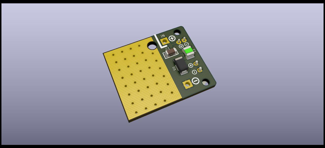
The input PCB incorporates a protection fuse, in-line shottky diode, an additional filter capacitor, an additional PCB heatsink, a JST-XH-2 power input, and a JST-PH-2 output for a battery gauge. I think this will prove to be useful...
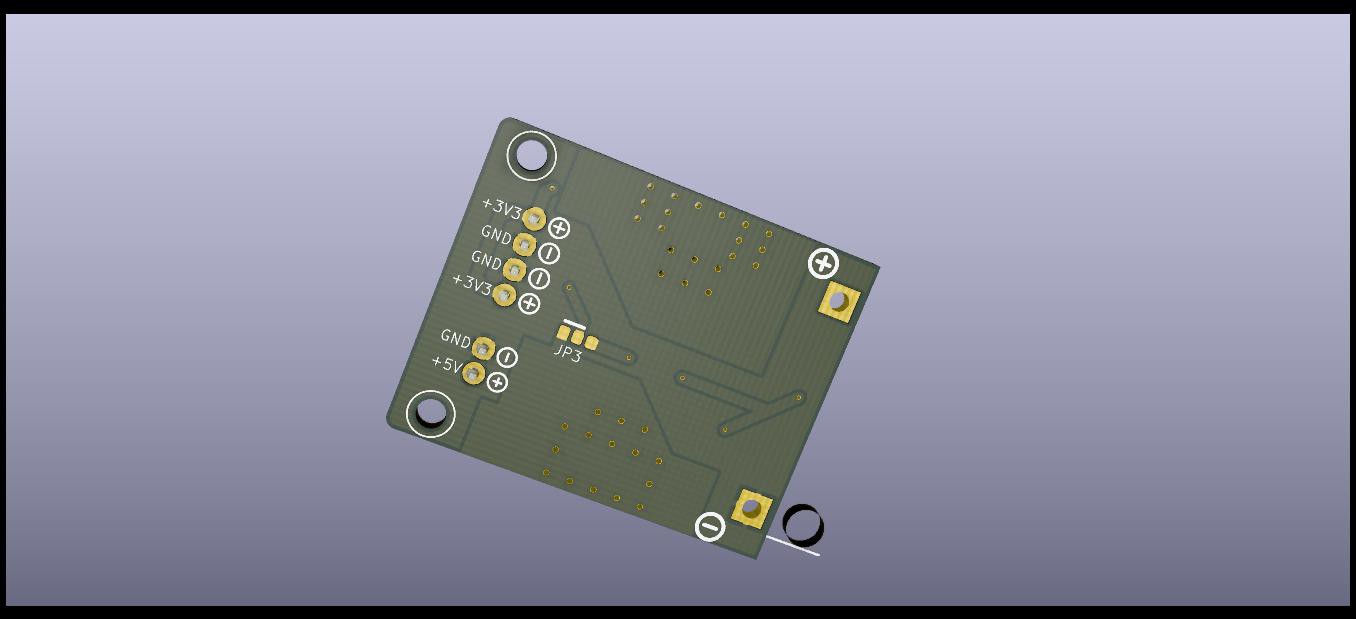
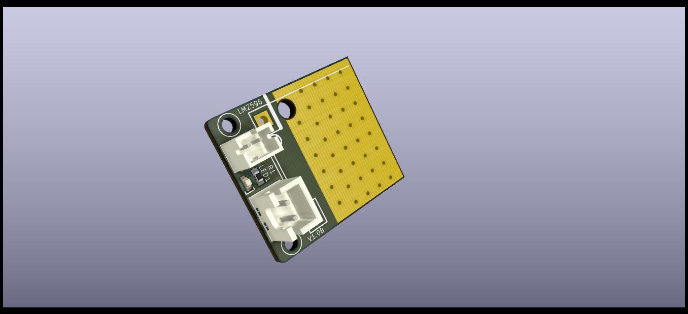
The bottom PCB Has a little more going on. It incorporates 2x LDO (low dropout) regulators; an AMS1117-3.3 and AMS1117-5.0. These are popular low-cost LDOs that are very affordable and do a decent job of creating smooth power rails for microcontrollers. There are also fuses for each output and LED indicators. Note, the 3D model actually doesn't show the solder mask that I removed in the power sections. I kept heat dissipation in mind for this, as we'll see when the PCBs arrive in a couple weeks. Also, disregard the floating drill there, that is something that I kept in my LM2596 module footprint for alignment purposes. (It has no effect on fabrication).
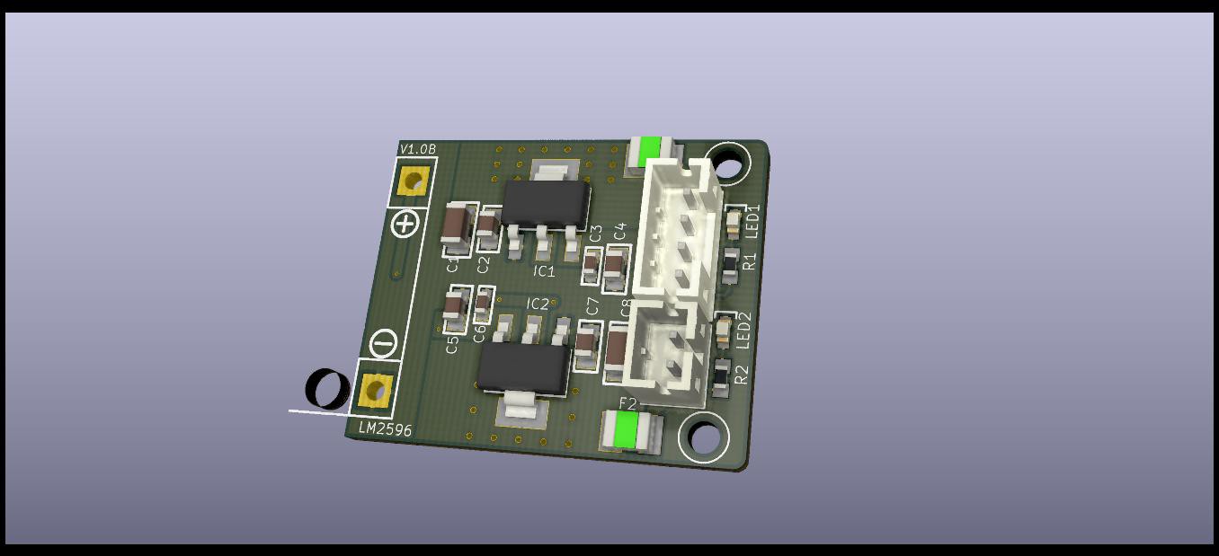
Here are the two PCBs + module combined, just begging for a 3D enclosure to be modeled! :D

(disregard the lack of detail on the Input PCB, KiCAD doesn't make it the easiest to export and re-import .step models. But this will do the job for the enclosure design and as a general mockup.).
With this set up, we have a respectable power module. It's a good place to start, so now it's on to more exciting things...
[coming soon...]
Discussions
Become a Hackaday.io Member
Create an account to leave a comment. Already have an account? Log In.