In order to get this project off the ground, I need to see if I can digitally control the wheelchair in my own custom firmware. For that, I need a "dummy load" to essentially fake out the wheelchair's onboard CPU and think that there is the old stock analog potentiometer connected, when in fact, it isn't.
-- DIGITAL POTENTIOMETER --
To do this, I selected a digital potentiometer with a simple to use interface protocol (I2C) and some decent available libraries that are compatible with the Arduino IDE platform. I decided on the MCP4661-502. It comes in a handy TSSOP package with 2x 5k-ohm potentiometers and also has built in NV (non-volitile) memory for saving settings after power off! This simplifies the code, so I won't need to make use of the Arduino Nano's EEPROM storage space (which would change when I upgrade to a better MCU).
The rheostat variant (MCP4662) could be programmed for this purpose as well, which is nice to know, since there are supply shortages during this time.
Later, I would like to add a 2nd 50k-ohm digital pot to replace the stock analog speed dial as well (I'll go over that part later). This would give me more precise control of the speed curve in firmware. The analog dial is a 30k ohm pot set up as a rheostat.
I also went with the 8-bit version (257 steps / taps) for the most precision.
It should be noted that there is an SPI version of these digipots, which would of course be a little bit faster, since SPI is a faster communication protocool than I2C. But seeing that the wheelchair CPU already tolerates an incredible amount of dead time (something like 500ms), I'm not too concerned with update speeds. I'm running the I2C display at 400kb/s and the digipot even slower, with no issues at all sharing the bus (I2C supports up to 128 different devices on a single bus).
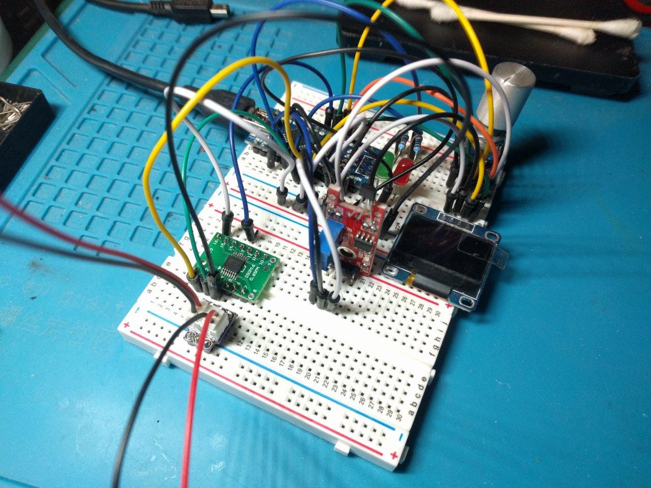
 Image description: test rig for firmware development. PCB daughter boards and a small 128x64 pixel display on top of white "breadboard" prototyping mount with many holes. Many wires of various colors are plugged in all over the place, patching connections.
This was a simple setup to start with, using some useful off-the-shelf parts. We have:
- Arduino Nano
- SSD1306 OLED display (widely supported, and easy to use with the Adafruit library)
- MCP4661 digital potentiomter
- generic rotary encoder (custom PCB with hardware debounce I designed)
- KY-024 analog hall effect sensor (we'll play with this more later)...
Fortunately, I wrote a lot of the firmware for another project last year using similar hardware. It didn't take too long to adapt it to this project. In fact, it was more work matching all the particular plugs and breakout cables to effectively connect this to the wheelchair and still be able to move it. But, behold:
[more to come...]
 CriptasticHacker
Discussions
Become a Hackaday.io Member
Create an account to leave a comment. Already have an account? Log In.