 CriptasticHacker
This project originated back in 2016 as a "cruise control" circuit to provide a simple pushbutton so that I can go full speed easily. This was for convenience and less pain- to keep from injuring my hands since the stock configuration forces me to squeeze the spring tension lever at all times.
The idea was simple: use a analog MUX to switch to 2x trim potentiometers (configured as rheostats). These function as a full-speed "dummy" load - tricking the CPU to think the lever was in the full speed potentiometer position. As long as the CPU doesn't mind the switch (dead) time of the MUX it should (and did!) work. The mobility scooter went full speed with the press of a button :)
Everything was done with 74 logic, so there was no firmware at all. I utilized a type D flip-flop (74HC74) and a simple debounce (74HC14) for the latching mechanism. In order to get the small footprints for the parts, I used the "LV1G" (ahem, overpriced) variants from TI. The circuitry is a little archaic, since these parts were designed in the 1970s and constitute some of the building blocks of all microcomputers.
Here's what it looked like:
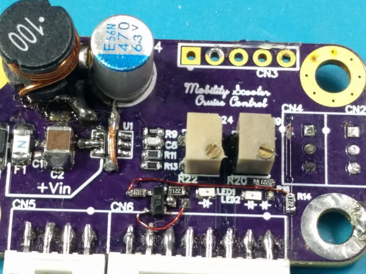
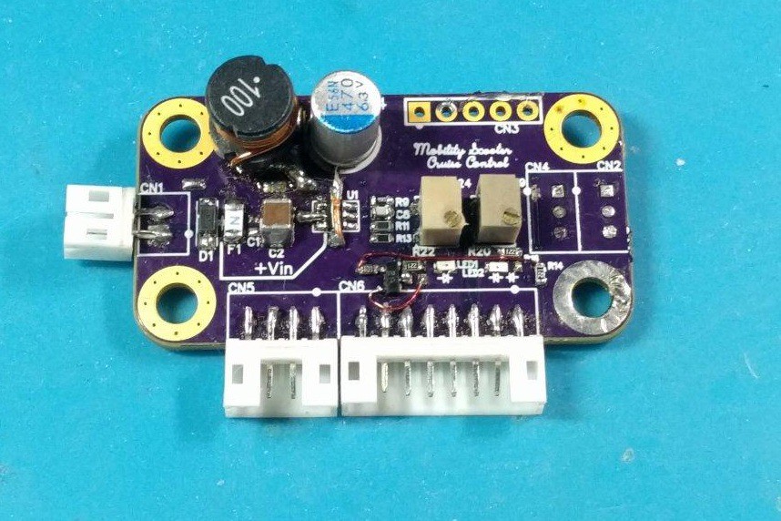
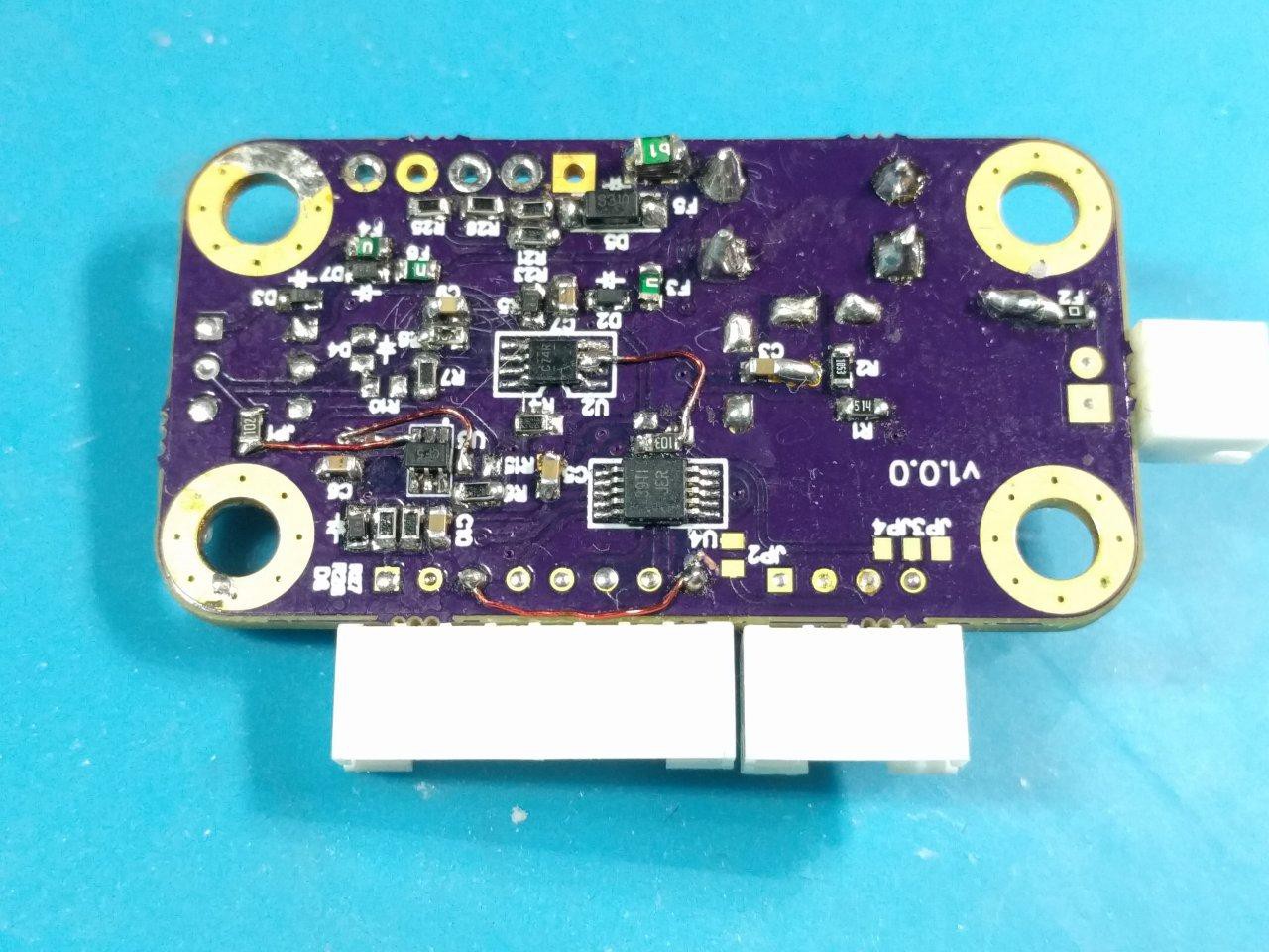
As you can see, the PCB had many flaws and required patchwork. It functioned though, and would probably still be working if I had an appropriate case for it. I believe the circuit got wet from the poor insulation of the tiller assembly and given it's amateur construction. I shelved it as a curiosity until something more robust could be developed with appropriate firmware.
I also over-engineered it to be small, as it did not have appropriate heat dissipation for the DC-DC converter accepting the +24V (nominal) battery input. You can see the copper bar that I soldered across the IC to help keep it from overheating. Additionally, F1 was not properly size for current, so when it blew, the wheelchair would no longer function... a very serious problem to be stranded in one of these.
Fortunately I planned ahead and had a safety kill switch to return back to manual controls.
I could go on with the flaws in this design, but I think that's enough self-criticism for now :P Better things are coming...!
Discussions
Become a Hackaday.io Member
Create an account to leave a comment. Already have an account? Log In.