My Solar Tracker
-
The construction - designing the brain of mysoltrk
05/30/2023 at 15:59 • 0 commentsWe spent quite a bit of time designing the circuit that will allow the panel to move with the movement of the sun.
Let's remember the fundamental points of this project:
- minimal hardware, low cost
- self-tracker device, without GPS or WIFI
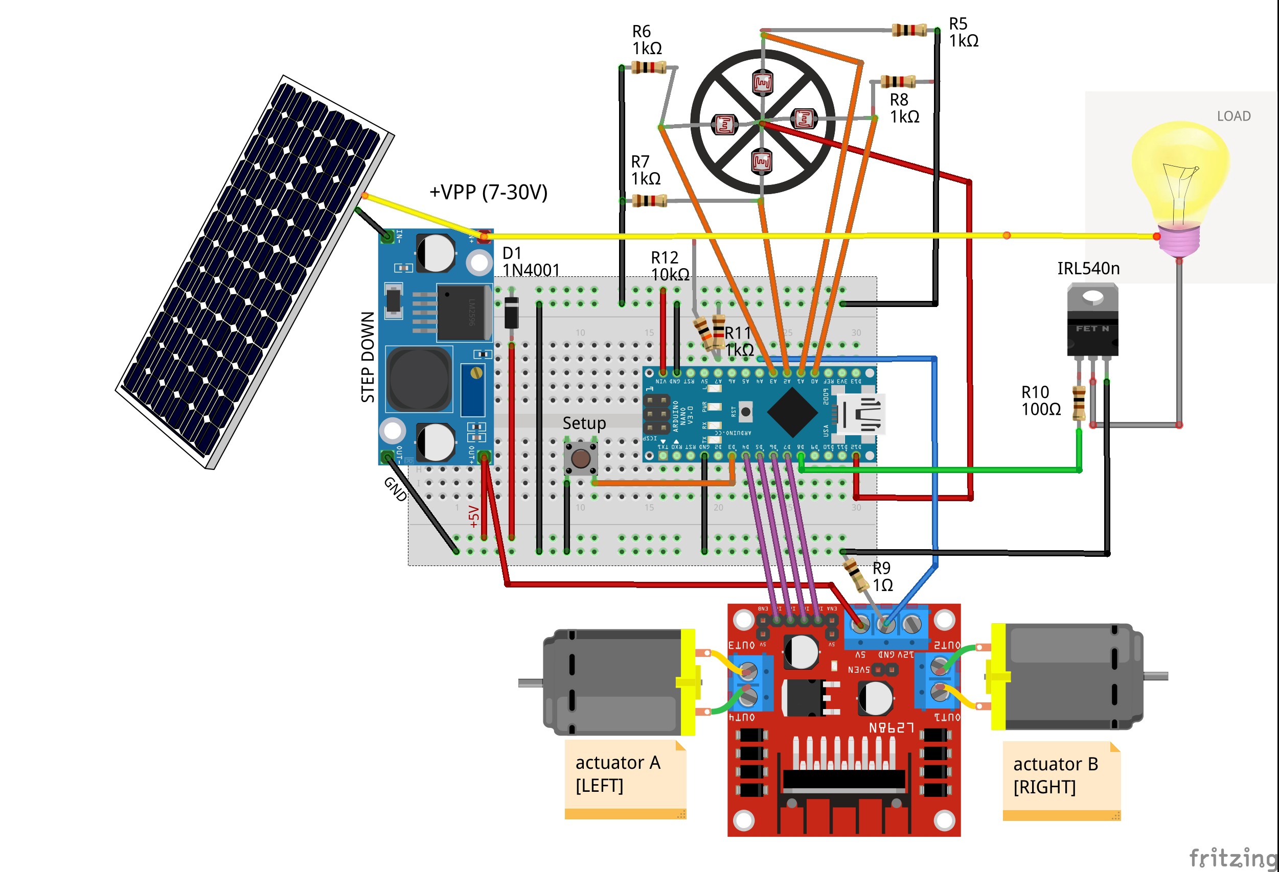
To fulfill this promise, we have come to realize this circuit:
![]()
As you can see, we tried to use easy to find components and a handful of passive components.Let's see the features together:
- CPU: we use a Arduino Nano as "brain" of mysoltrk. Low cost, low consuption and powerful enough for our project
- The board is powered by a step down, which reduces the voltage of the solar panel to 5V. Since there are so many step down, we picked one that delivers enough amps for the motors
- L298N: used to decouple the logic gates of the Arduino from the motors
- Photoresistors: with a simple divider we can interface the photoresistors to the Arduino
- IRL540n: used as a relay
- 1N4001 to protect Arduino when it is powered via USB and via solar panel at the same time
- We add a setup button, it will be useful in the future
There are some interesting points to note:
R9 Shunt resistor
We use shunt resistor to check the work of actuators.
Since our 3D printed actuators doesn't include limits switches, measuring the shunt value we can deduce this condition.
R11/R12 voltage divider
With this simple trick we can evaluate if the panel delivers enough energy to drive the actuator.
The calculation should be simple: read the value before and after running a motor.
IRL540n
Depending on the type/size of the solar panel, the power may not be enough to drive motors and external load at the same time, so we decided that the load should be controlled by mysoltrk.
For example, if there is not enough light, we can decide to use the panel's energy to drive actuators or to charge.
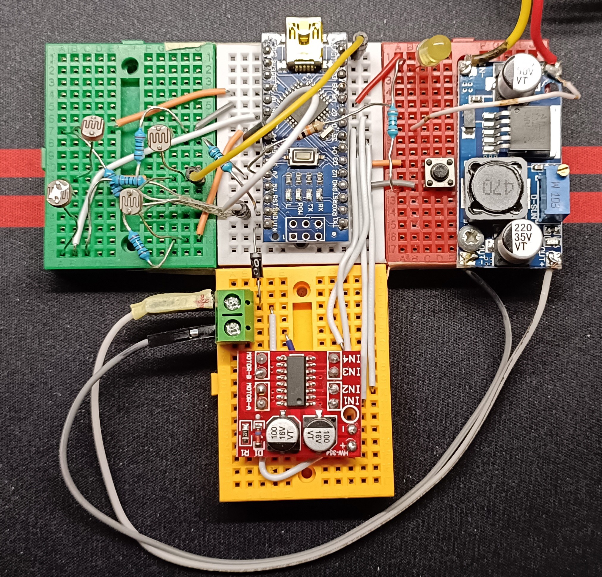
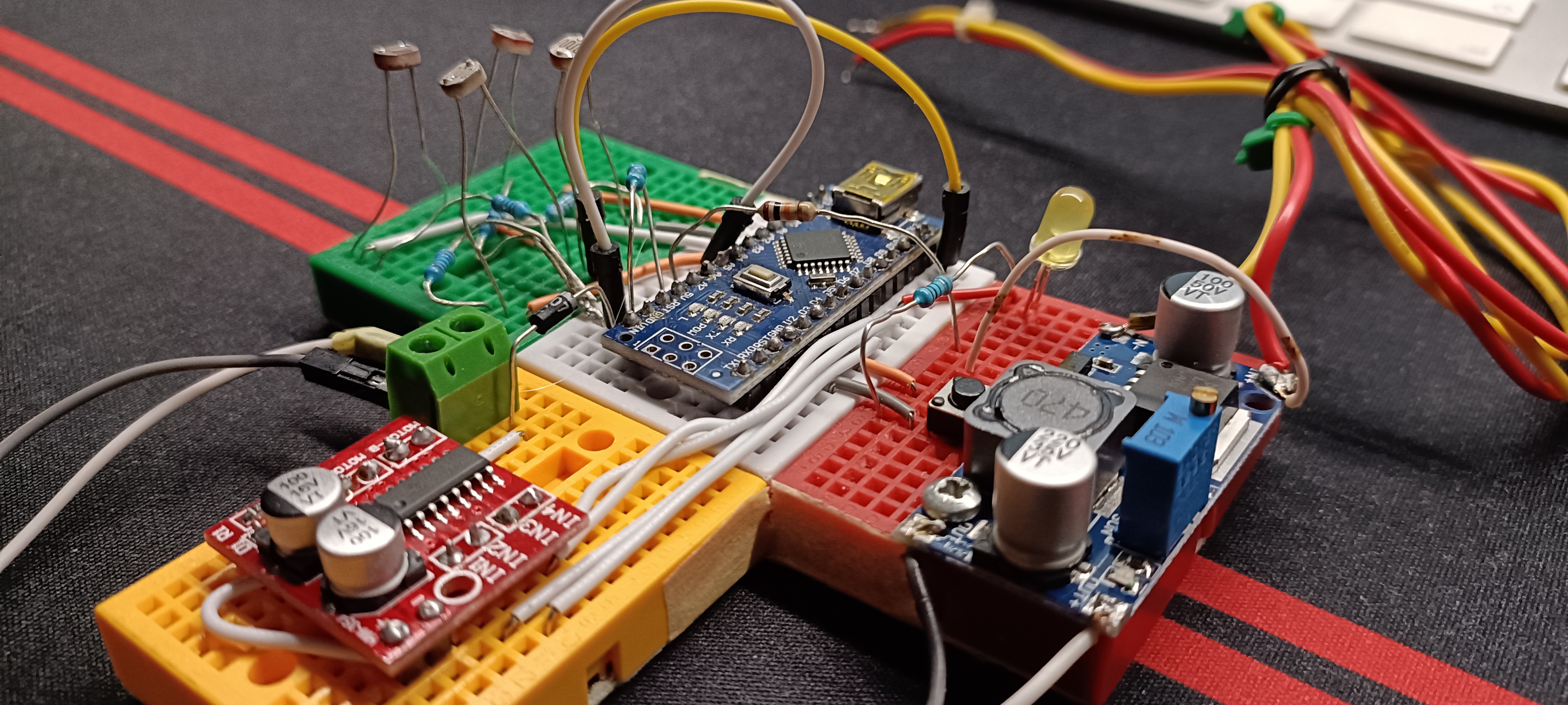
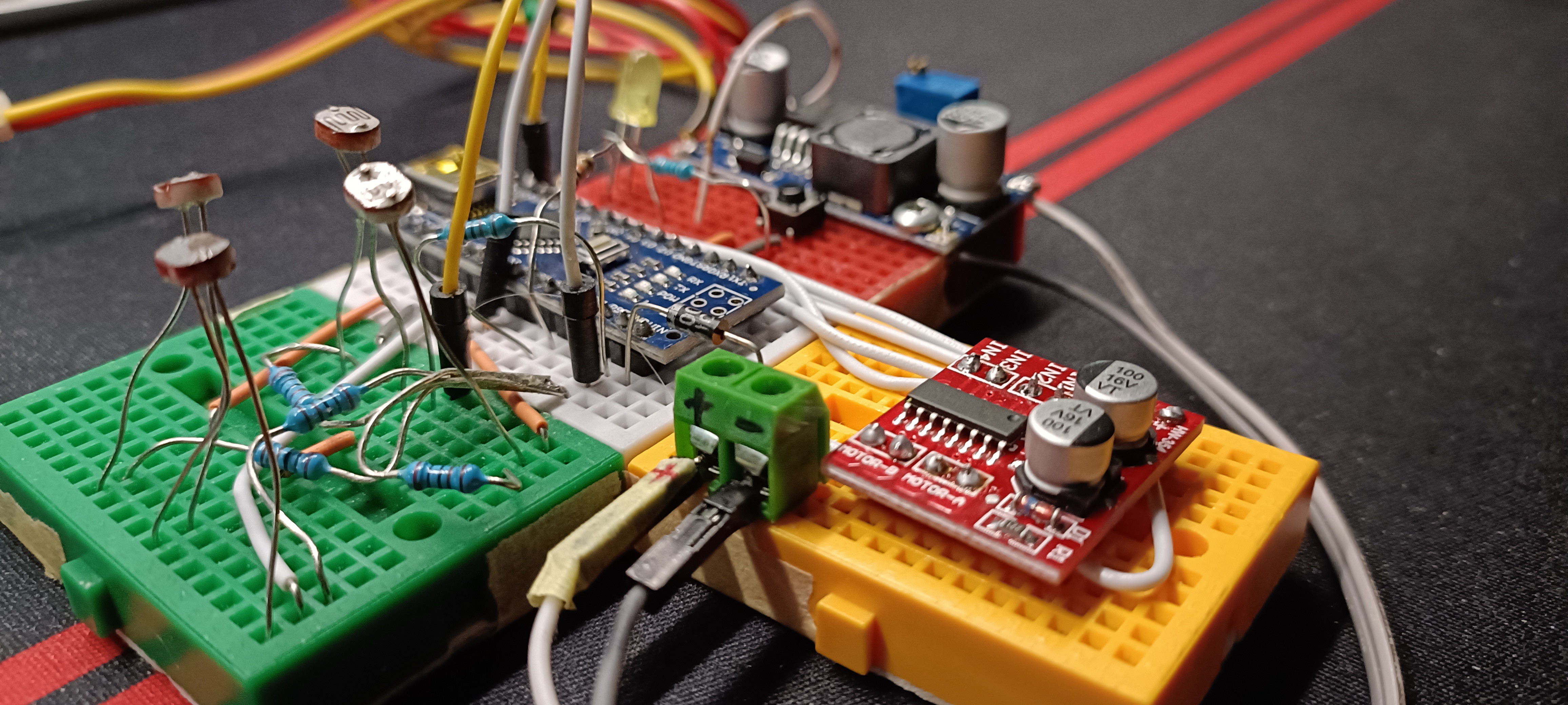
Before designing a printed circuit board, we want to try it with a breadboard in order to verify the correctness of the starting hypotheses:
![]()
Note: in this photo the shunt resistor is missing (a late order)
![]()
![]()
Now we can start to write code to test actuators and photoresistors.
-
The construction - part two
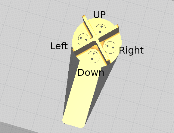
05/15/2023 at 19:59 • 0 commentsTo complete the build of our solar tracker, we need a "viewfinder" for the sun.
Here our viewfinder:![]()
As you can imagine, with this object we can read the light values divided by up/down/left/right
![]()
It must be placed on top of the solar panel. The long plastic tab allows you to position it with a certain degree of freedom.
We think that this is the last 3D printed object.
Now we will focus on the circuit building. Stay tuned..
-
The construction - testing movements
05/07/2023 at 07:14 • 0 commentsHere is a video explaining how the movements will be implemented:
Next challenge will be create a board to pilot this tracker.
-
The construction - part one
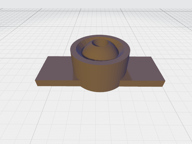
05/02/2023 at 13:14 • 0 commentsAfter having built the actuators, the next challenge is to create a type of support that allows the movements generated by the new three-way support.
Here our approach for the actuators:
![]()
For the panel support:
![]()
We have arranged drilled holes to use with screws to lock the support to the panel.
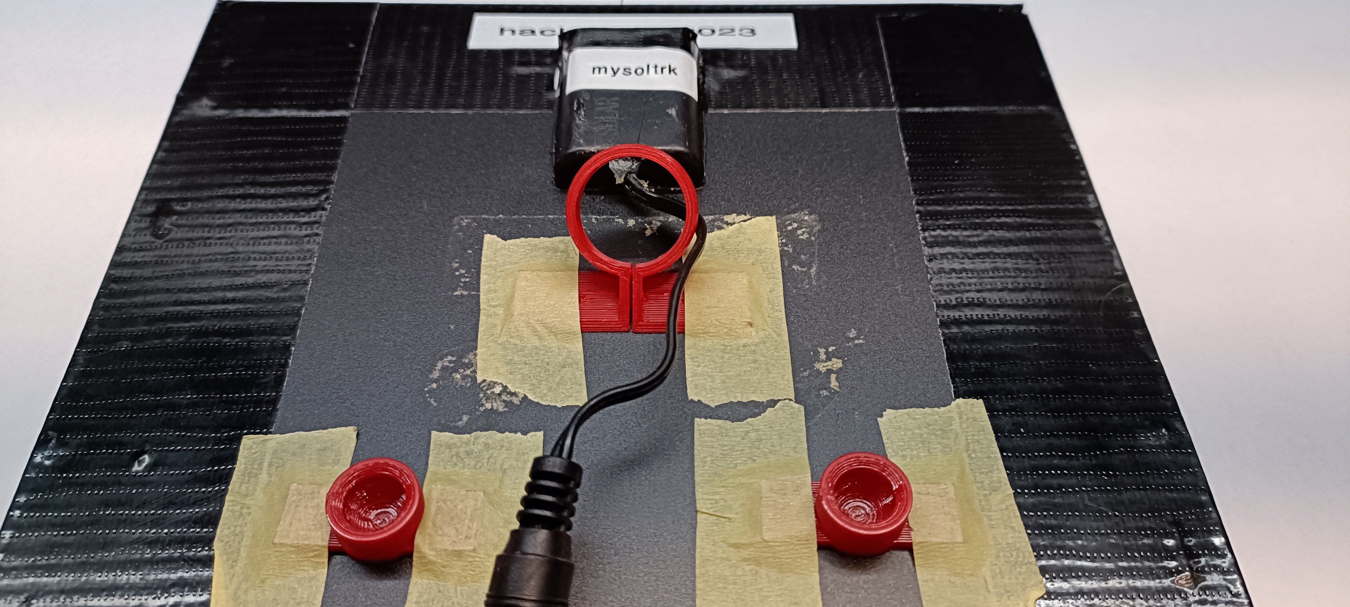
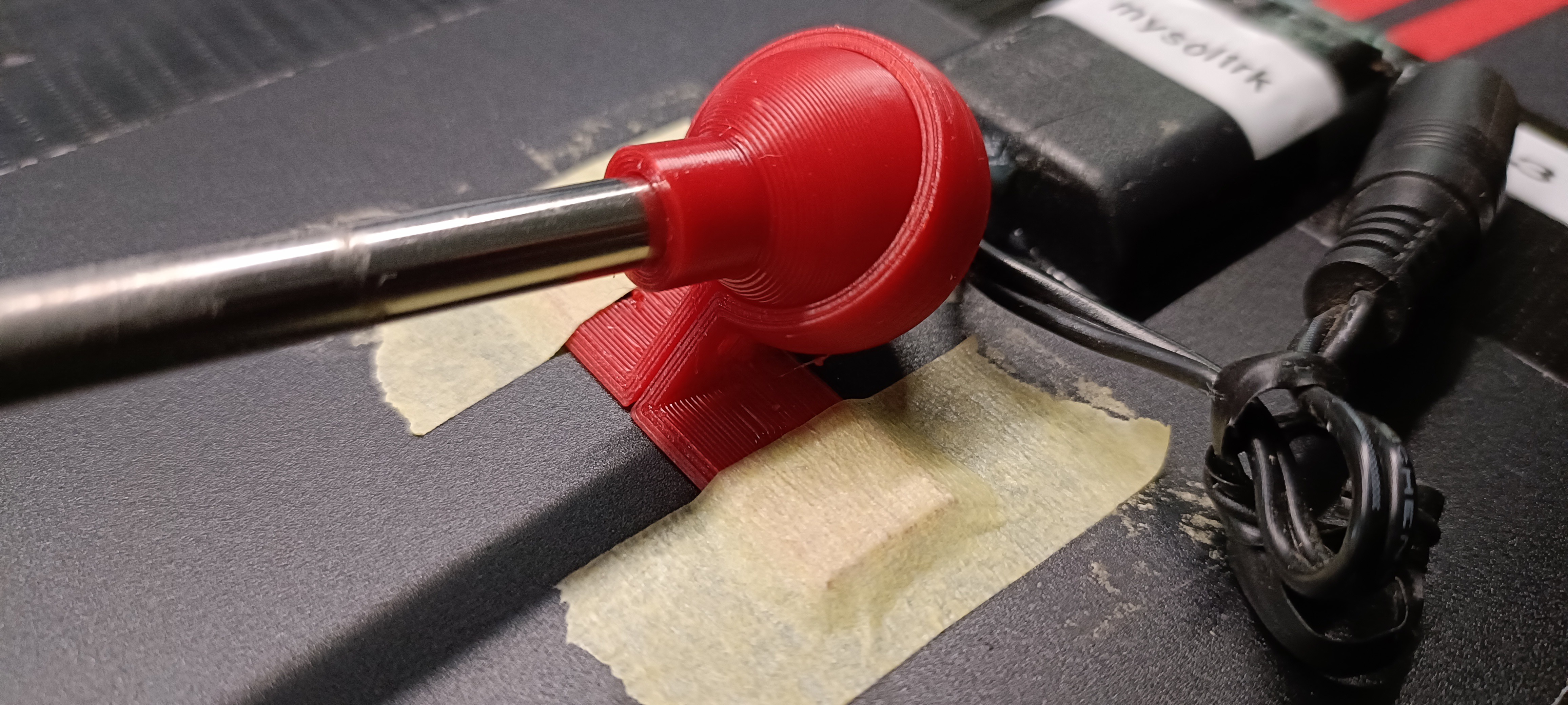
For this project, we've used a solar panel with size 21x19cm, light enough to allow us to experiment with the movements using tape to keep the newly made pieces together:
![]()
It's not very professional, but it allows us to find the right positioning of the three joints.
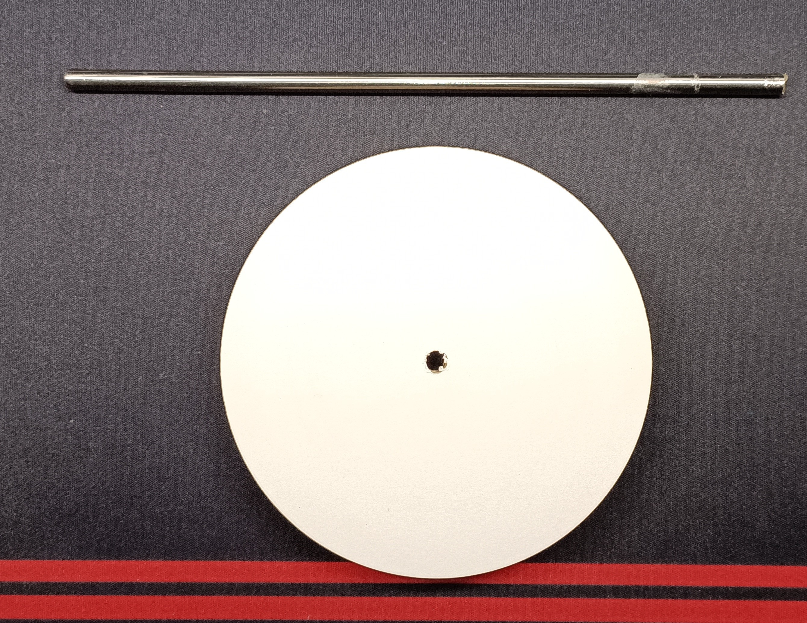
The next step is to create a stand for the panel. In this case we found some materials in garage, probably bought in some hardware store time ago for other DYI projects.
For this part of project have fun with your imagination and your dexterity
![]()
The tube has 6mm diameter and a height of about 20cm, the round stand (used for the base) is plywood of about 12cm in diameter. Obviously, you can use a different stand form.
Here is the detail of how the joint is attached to the panel:
![]()
Here final result (for prototype number 1):
![]()
Some notes for assembling:
The sphere inside actuator support can be removed easily. Just screw it to the actuator and then you can pull it out.
The rounded plywood square was added during assembling for movements study
-
A little linear actuator
04/20/2023 at 12:57 • 0 commentsThe first obstacle to face for this project was to create a linear actuator useful for the foreseen movements.
After lot of try and retry, here is the fourth version of linear actuator, with these characteristics:
- solid enough to move a 10/15Watts panel
- quite resistant to rain,dust and wind
- simple to assemble, no screws to hold the pieces together
- a mechanism to lock shaft to limit
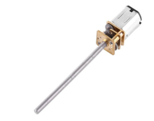
About the engine, the choice fell on N20 tiny motor
![]()
We used the 6V 30rpm version, to ensure we had enough force to lift the panel.
Very slow but for sun movements is enough.
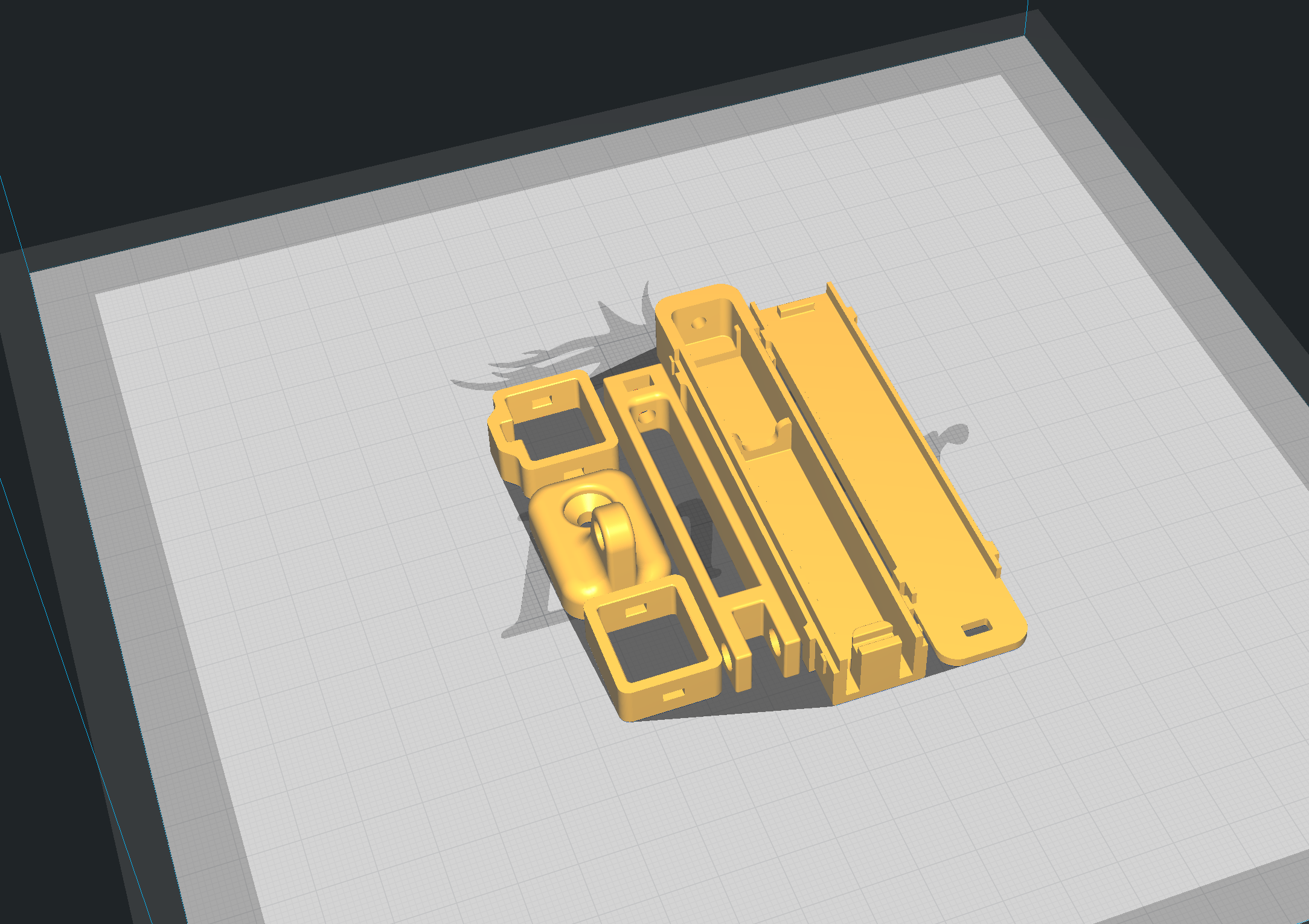
Here the 3d object:
![]()
and the hardware you need to assemble:
![]()
Some useful info for build:
- We used PETG. PLA is not suitable for this kind of objects
- Always printed in draft mode (0.28), support enable only if you need perfect hole (you can use screwdriver to enlarge and/or clean)
mysoltrk - a solar tracker, reinvented
A different approach for a solar tracker, alternative movements, to be installed on the outside, to optimize the efficiency of solar panels