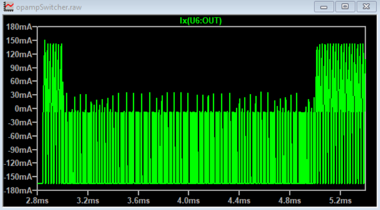
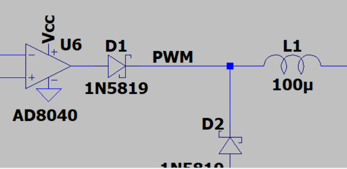
A buck regulator fundamentally pulses current through an LC filter, which makes a DC output.
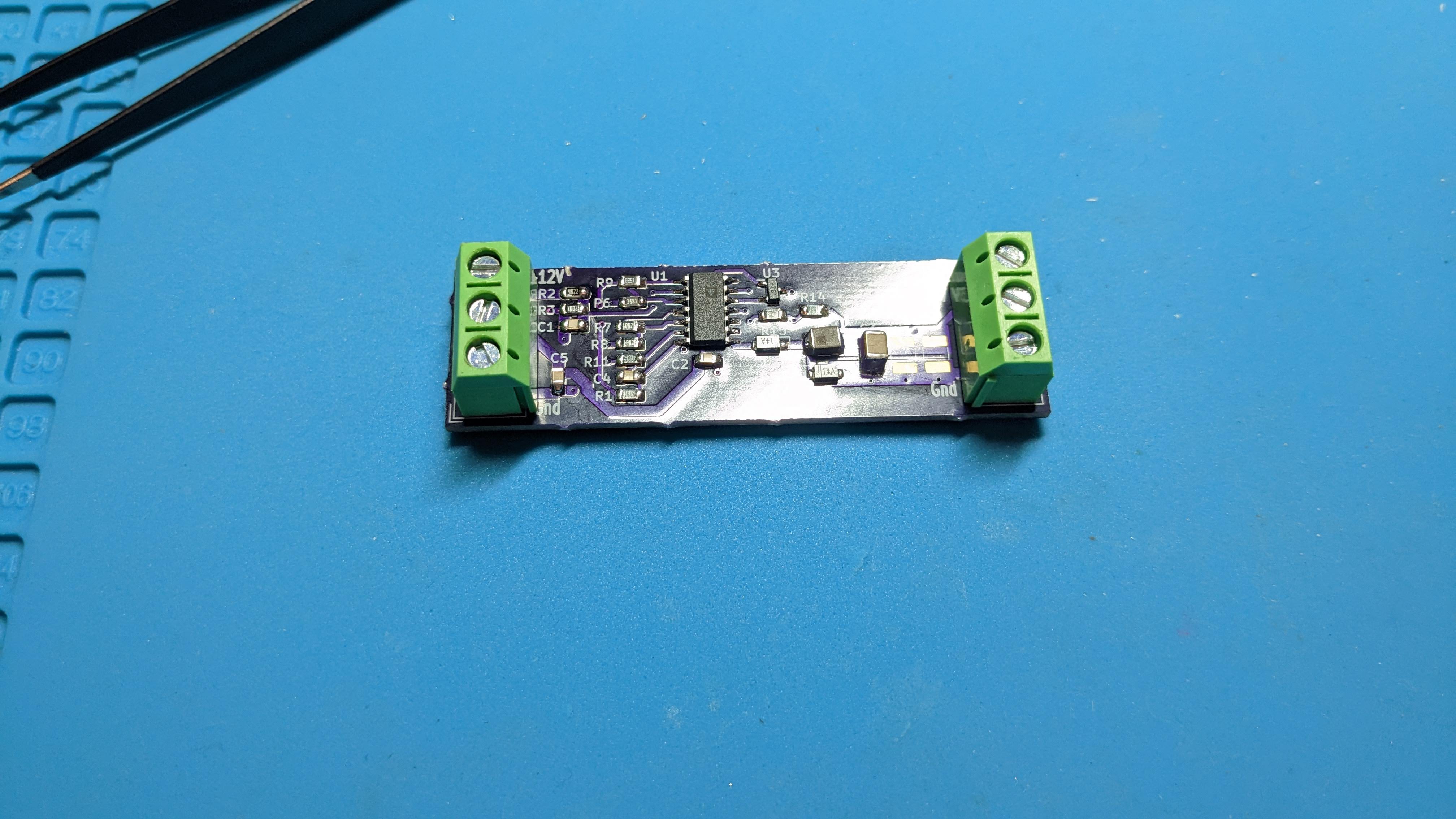
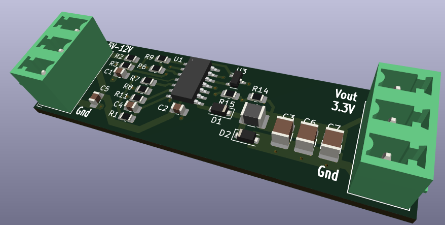
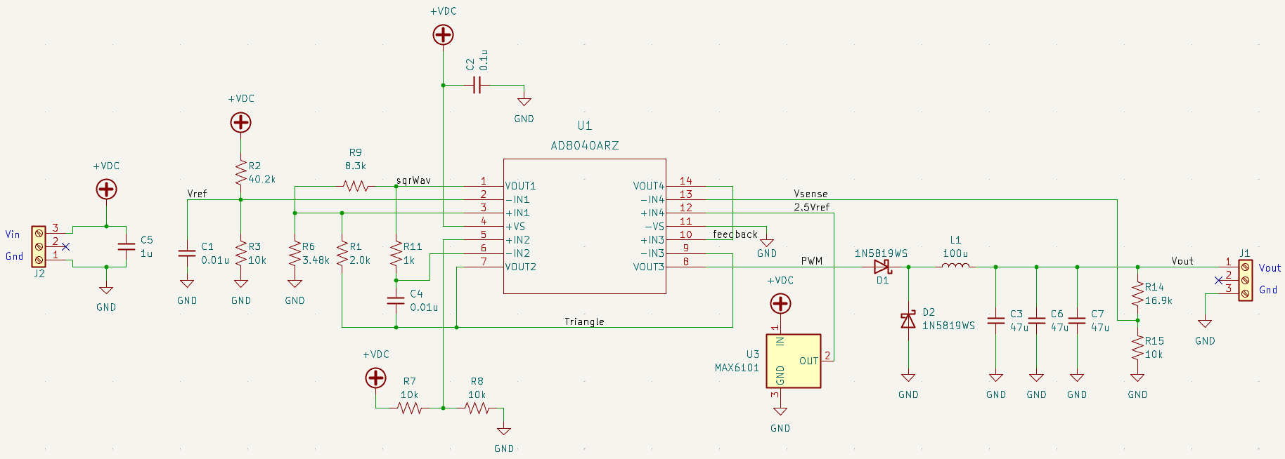
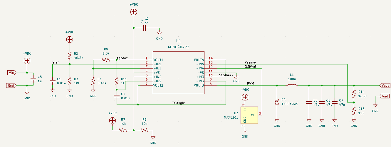
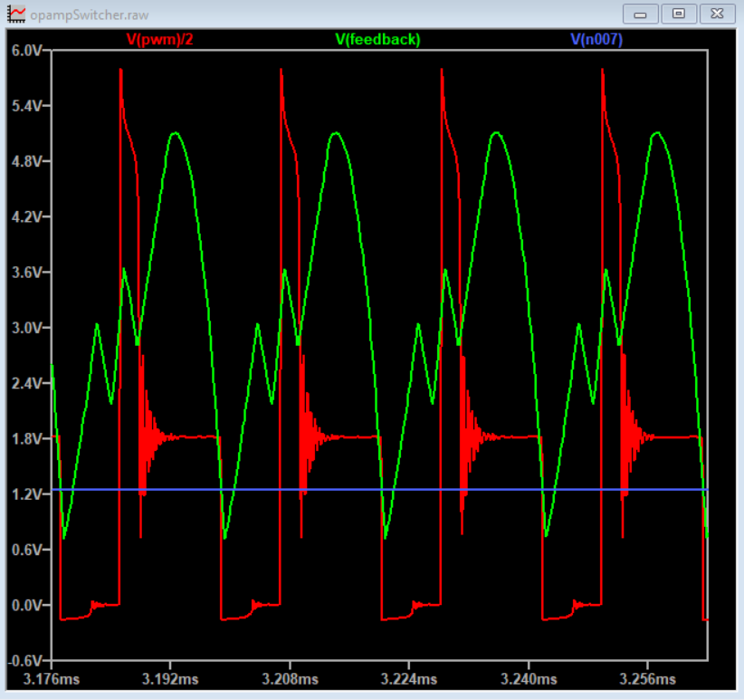
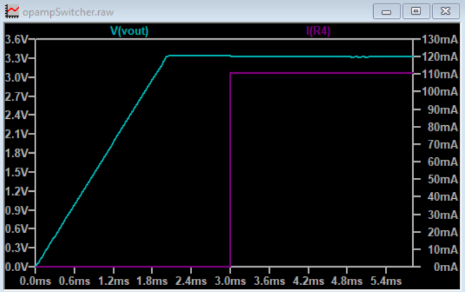
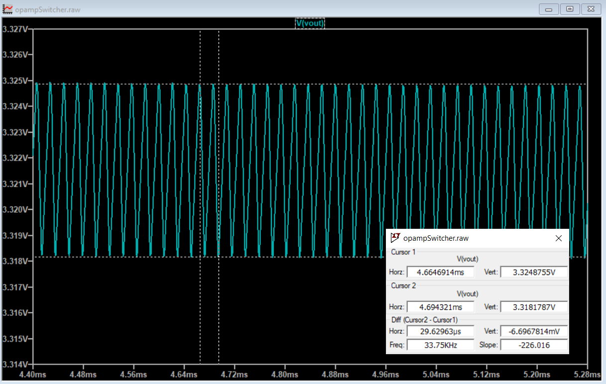
This project uses a quad opamp package to create a triangle wave which feeds into a comparator stage to create a PWM output. The PWM output then goes through the LC filter to create a DC level. That DC level is then sampled and fed back to the comparator to control the PWM width which regulates the output voltage.
In the name of technology, I used ChatGPT to help write the details (human edited for clarity and/or correctness):
--- Begin ChatGPT
Design the basic buck regulator topology
The basic buck regulator topology consists of an input capacitor, an inductor, and an output capacitor. The input capacitor is connected to the input voltage source, and the output capacitor is connected to the output load. The inductor is connected between the output opamp and the output capacitor. This creates a low-pass filter that smooths out the output voltage.
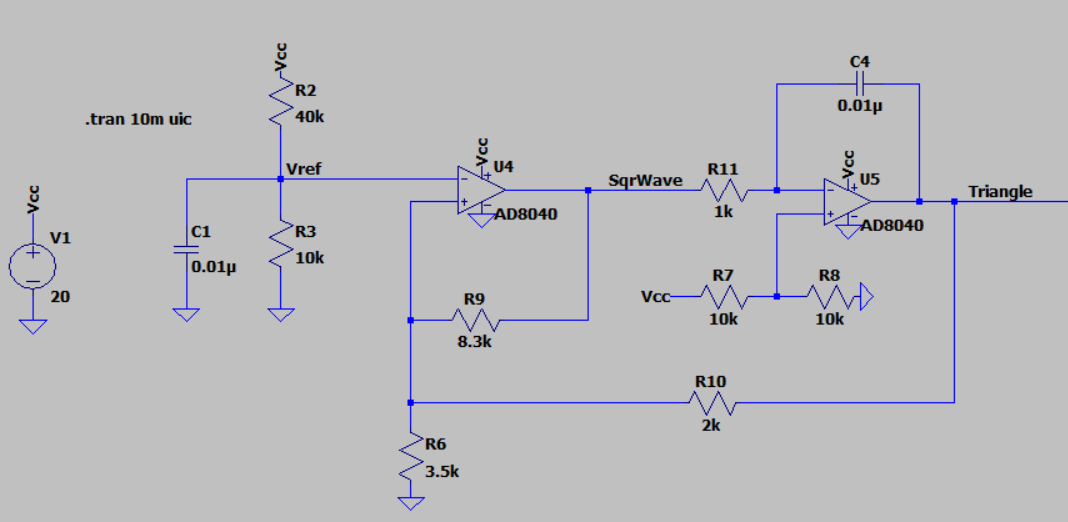
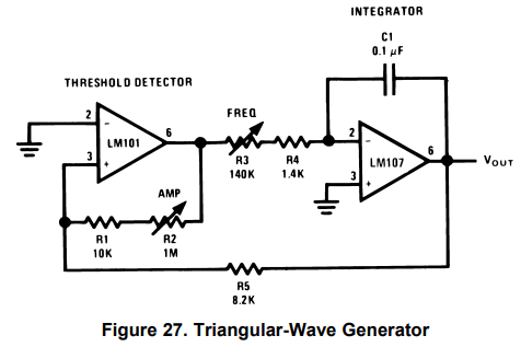
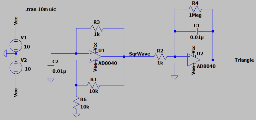
The first opamp is configured as a Schmitt trigger, a circuit that produces a binary output based on the input voltage level. When the input voltage exceeds a certain threshold voltage, the output switches from a low state to a high state. When the input voltage drops below a different threshold voltage, the output switches from a high state to a low state. The hysteresis created by the two different threshold voltages helps to ensure that the output will not switch rapidly back and forth around the threshold voltage, which could cause instability and noise in the system.
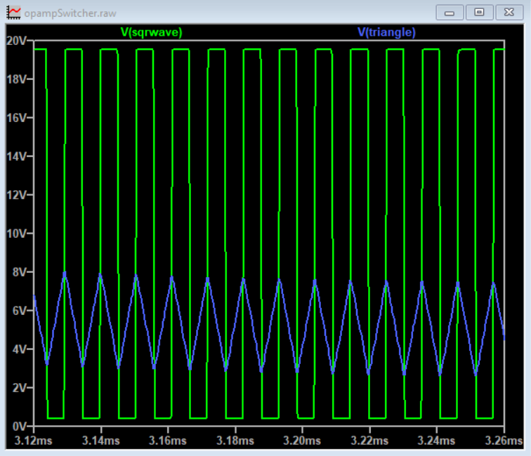
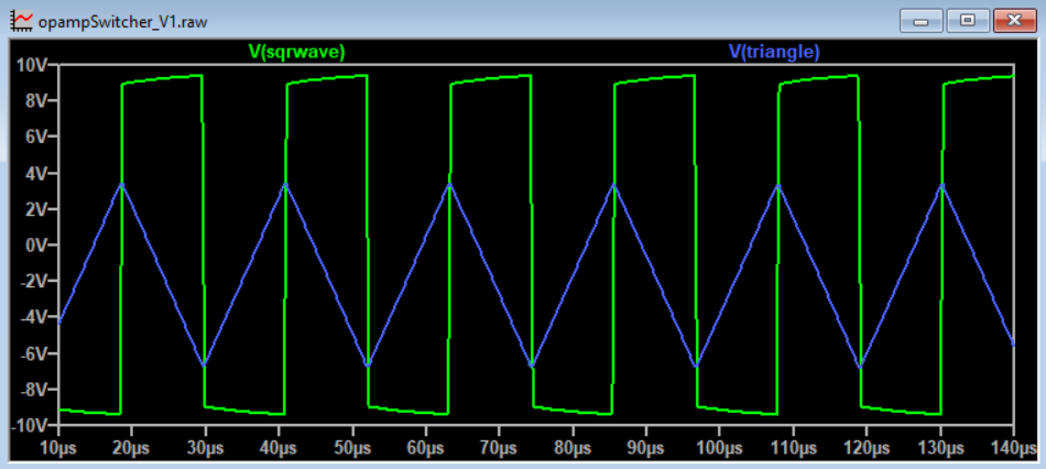
Connect the output of the Schmitt trigger to an integrator circuit, opamp 2, which is simply an op-amp configured as a voltage follower with a capacitor (C) in the feedback loop. This will produce a triangle wave at the output of the integrator, with the frequency determined by the values of Rf and C. By combining the Schmitt trigger and the integrator, you can create a triangle wave with precise control over its frequency and amplitude.
The output of the third op-amp, which is used as a comparator, will be a PWM signal that is proportional to the difference between the output voltage and the reference voltage.
The fourth op-amp will now be used as a voltage amplifier with a gain of 1. A MAX6101 voltage reference chip will be used to create a reference voltage that will be compared to the output voltage. The output of this op-amp will be connected to the non-inverting input of the third opamp (comparator) to create a feedback loop to regulate the output voltage.
---End ChatGPT
The Schmitt Trigger and integrator forms a triangle wave at about 86kHz. The triangular-wave frequency is determined by R11, C4 and the positive and negative saturation voltages of the Schmitt Trigger opamp.



This is perhaps a demo of when an op-amp should not be used. A $0.50 quad comparator would do a much better job than an op-amp in this application, with some circuit changes of course. "I used ChatGPT to help write the details" Belated lol on that. Good one!