-
Is this the best choice?
05/21/2023 at 20:49 • 0 commentsWell, after many investigations, it would appear that this opamp pulls a lot of current when it is oscillating. The sim agrees with reality in this regard too.
So, while it is a great regulator, and has great transient response, it is not efficient at all. It is probably worse than most modern LDO chips.
-
Testing
05/10/2023 at 03:52 • 0 commentsHere is where the rubber meets the road.
![]()
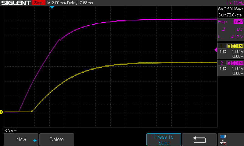
Purple is the input voltage 6V and yellow is the output voltage 3.3V
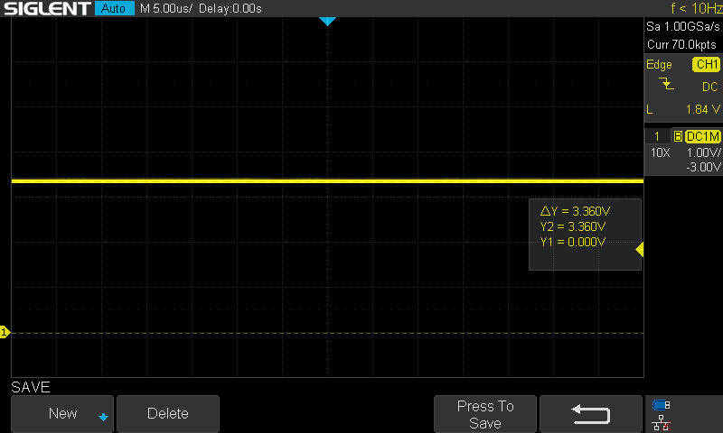
Looks pretty smooth and 3.36V, hits the target...
How about we zoom in a bit on that?
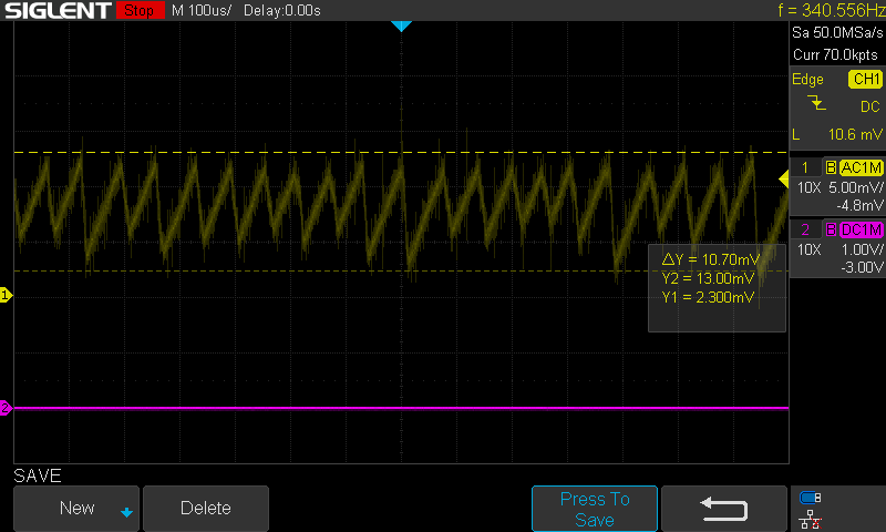
![]()
Put the scope into AC mode and zoomed in on the vertical scale. 10.7mVpp and I only have one 47uF output capacitor installed!
![]()
It's a switching regulator, so how efficient is it?
With a 68 ohm resistor as the load, that makes 3.3^2 / 68 = 160mW output power (3.3V / 68 = 48mA ).
The input power was between 6V * 94.8mA = 568mW and 11.3V * 68mA = 768mW
That puts the efficiency at a measly 160mW / 768mW * 100 = 20% to 160mW / 568mW * 100 = 28%
The opamp is getting quite toasty. A quick look at the datasheet indicates each of the 4 amps should only consume ~1.75mA max.
Something else is amiss...
-
PCBs and parts have arrived
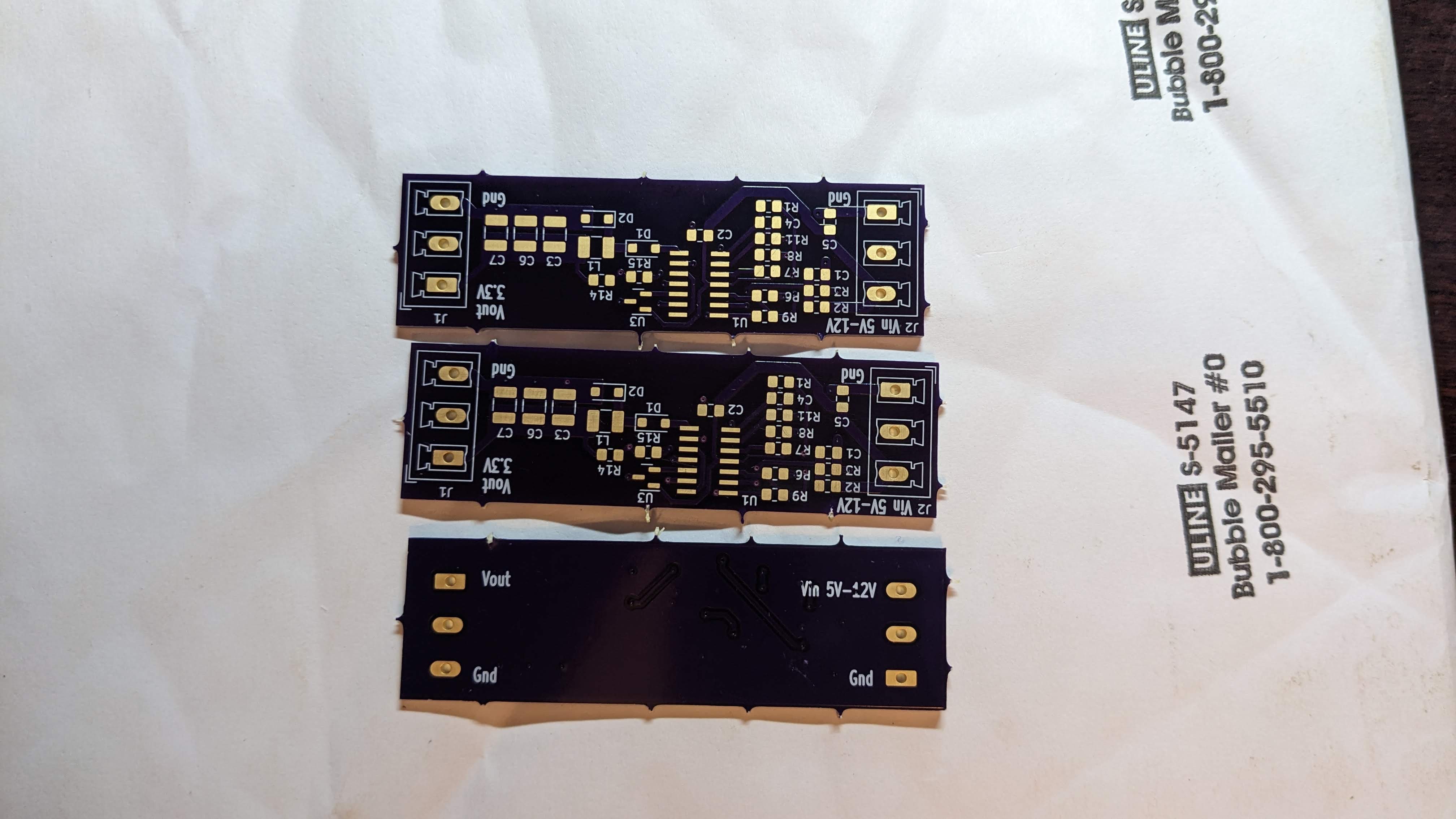
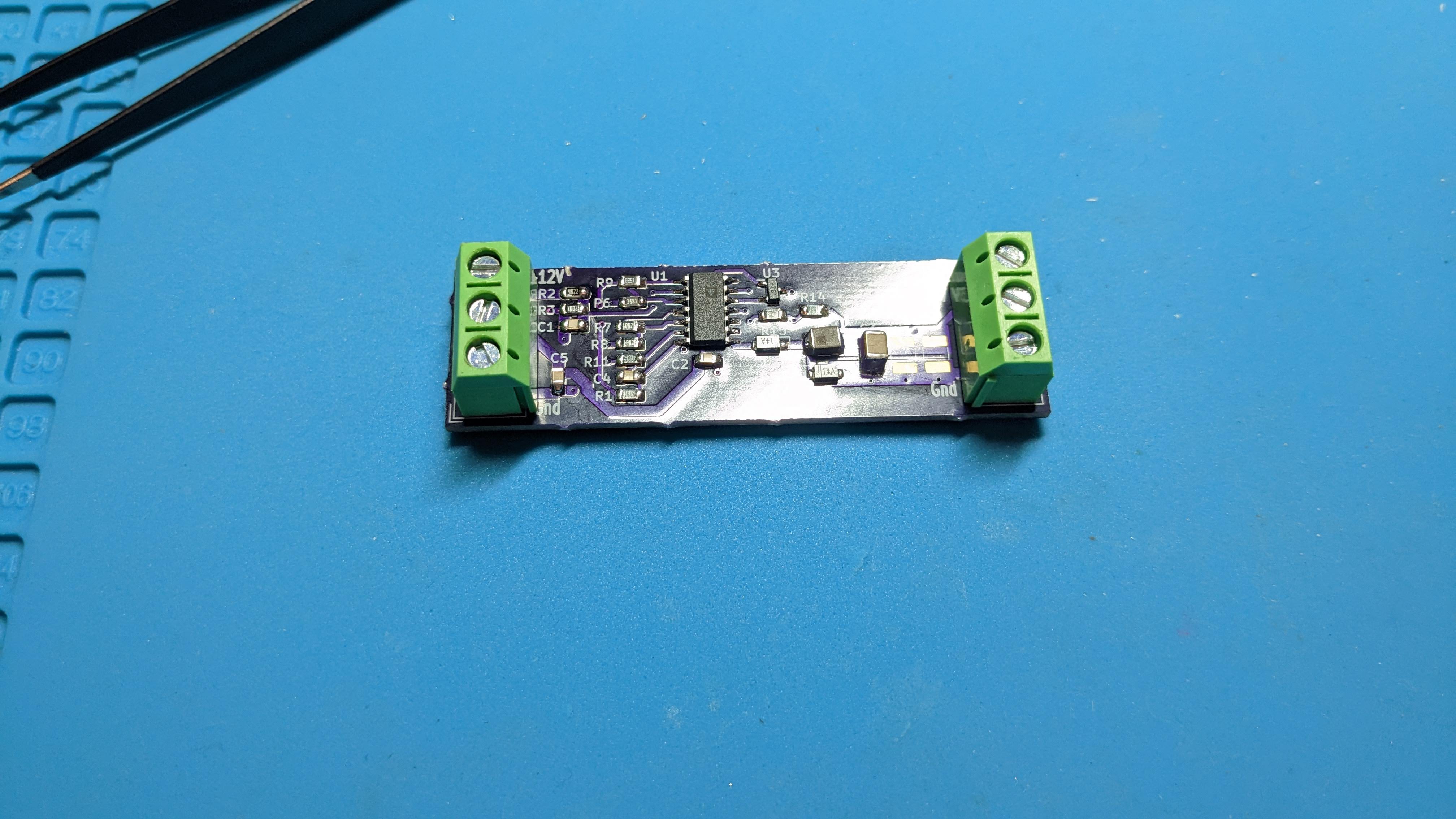
05/09/2023 at 01:31 • 0 commentsParts are here, PCBs are here...time to build.
![]()
Some time passes......
![]()
All the parts fit like a glove.
-
PCB Layout
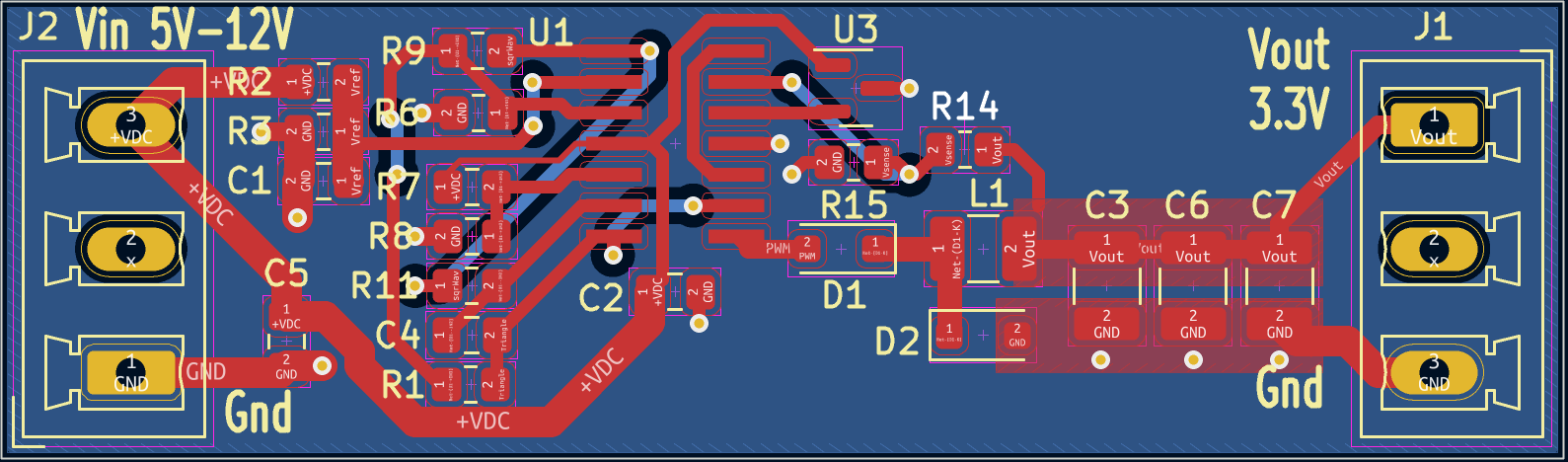
04/23/2023 at 21:51 • 0 commentsPCB layout done:
All parts are on the top side. Total area is 1.8in-sq.
![]()
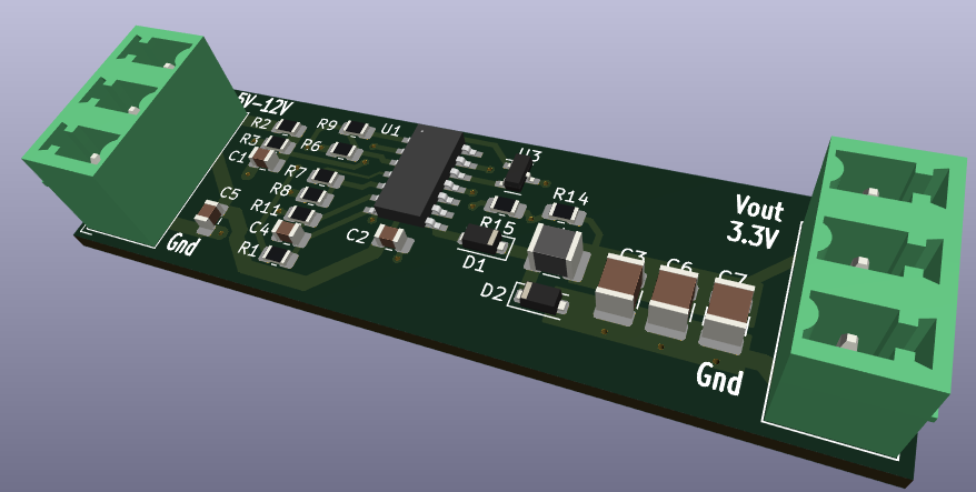
And a cool 3D view of what to expect when it's built:
![]()
-
Totem Pole Output VS a FET Switch
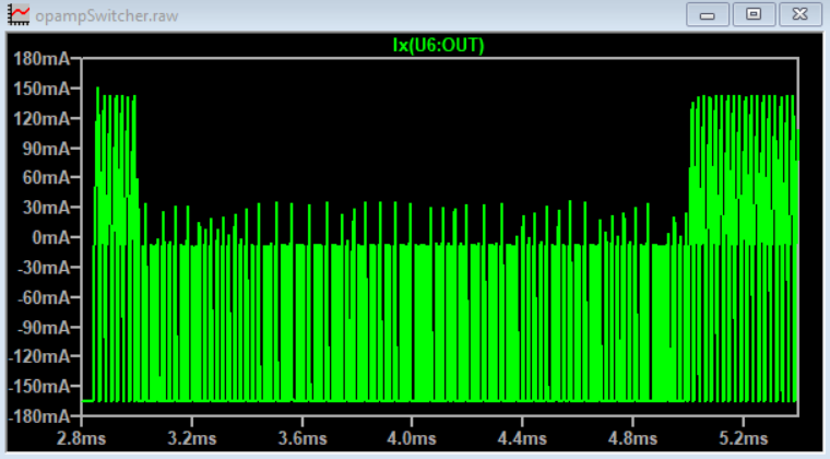
04/23/2023 at 17:07 • 0 commentsWhile doing a few final checks, I thought I'd check the currents from the opamp.
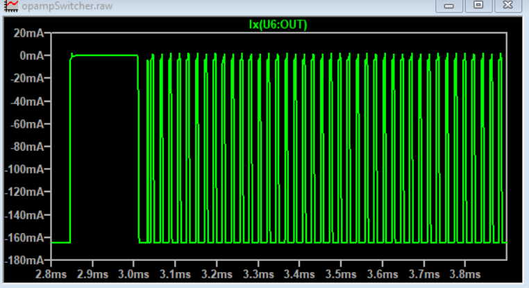
Whoa! The current is going plus and minus!
![]()
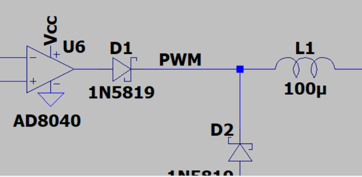
This makes total sense, the output of the opamp is designed to sink AND source current. We only want it to source current. Adding a diode to the output of the opamp will solve that.
![]()
Much better, current is only going in one direction now.
![]()
And our new kiCAD drawing:
![]()
-
Schematic Capture
04/23/2023 at 16:30 • 0 commentsSatisfied with the simulations performance, it's time to start making it for real.
Step one, schematic capture. I use KiCAD 6, and found that there was an update to version 7 during the middle of drawing. I was getting frustrated with how KiCAD deals with wires when dragging components around. During my search for a solution, I found that version 7 is the solution. Normally I don't update software in the middle of a project, but I took a calculated risk, and the transition was seamless. Score!
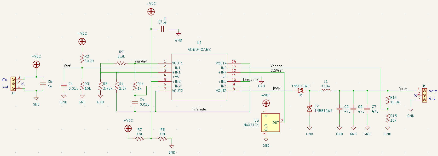
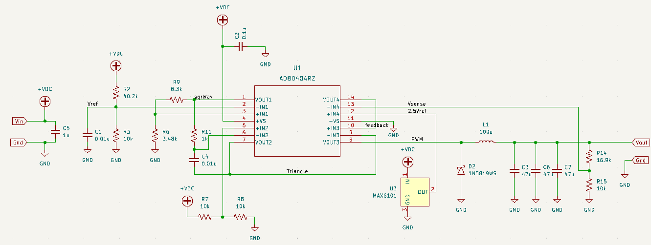
I made three minor changes (as compared to the LTSpice schematic) as I was drafting the schematic.
- The 1.25V reference was changed. The LT1389 is a 0.05% accurate part, and costs about $8 USD. So I changed it to a MAX6101, 0.4% accurate and only $1.48 USD.
- The output capacitance. Instead of a single component, I made room for three. This will give more flexibility during testing.
- I also added a bypass capacitor for the opamp package and input connection.
![]()
-
Complete Regulator
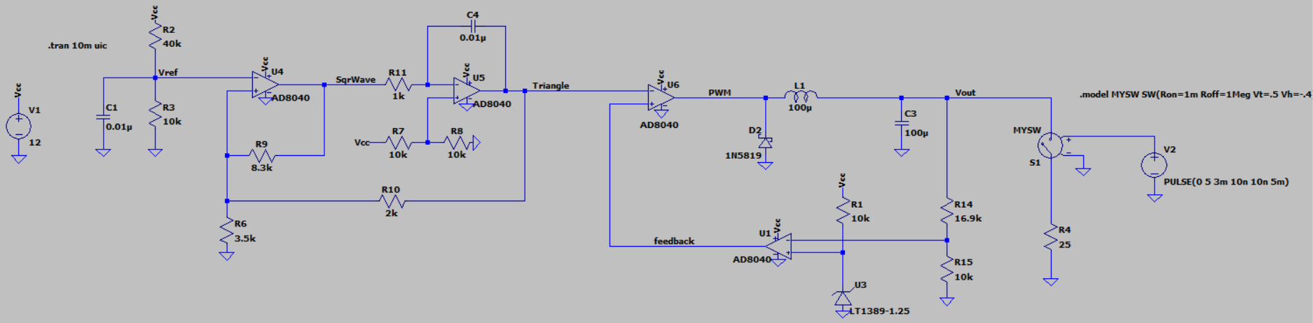
04/19/2023 at 05:02 • 0 commentsAfter a few nights plunking away on LTSpice, I finally had a working regulator.
![]()
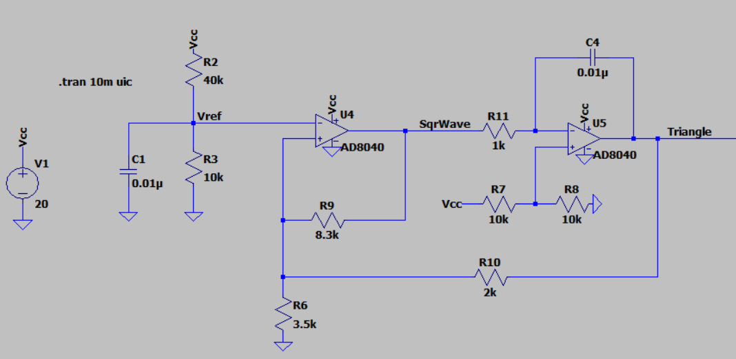
U4 is a Schmitt Trigger used to make a square wave. R2, R3 shift the switching thresholds for it up into positive voltages. R9, R6 set the thresholds and R10 moves them depending on if the next stage (U5) is ramping up or ramping down.
U5 is the integrator, which converts the square wave input from U4 into a triangle wave output. The output of which is fed back to the Schmitt Trigger to cause it to toggle. Together they form a stable oscillator with a triangle wave output.
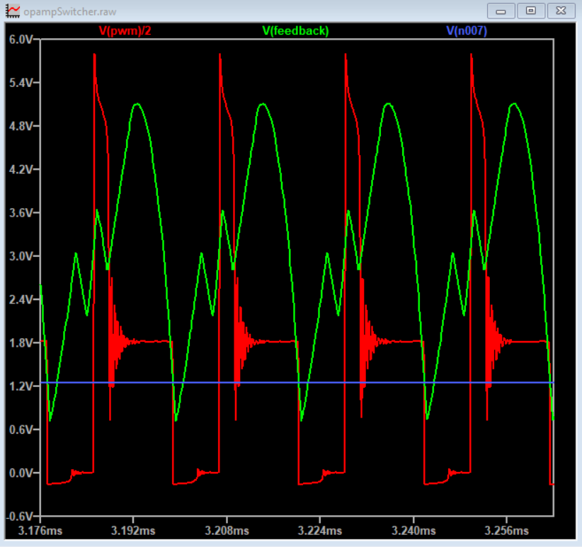
Next is U6. It compares the present value of the triangle wave to a threshold (feedback) value and as that value changes, the output will toggle based on the portion of the triangle wave being fed into the negative input. This creates the PWM.
The PWM is then fed into the LC filter of the buck circuit, then R14,R15 sample the output voltage and feed it back into U1. U1 acts as a comparator and compares the feedback voltage to the 1.25V reference U3. If the Vout voltage is too high, then U1 will output a low value, and if it is too high it will output a higher value.
V(n007) is the voltage divider node, going into U1 minus input. V(pwm) is divided by 2 just to keep the graph more readable.
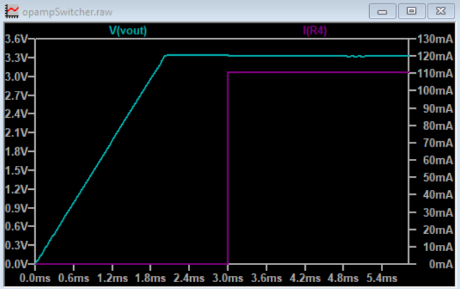
![]()
And the ultimate test, the output (does it work?)
3.3V @ 110mA
![]()
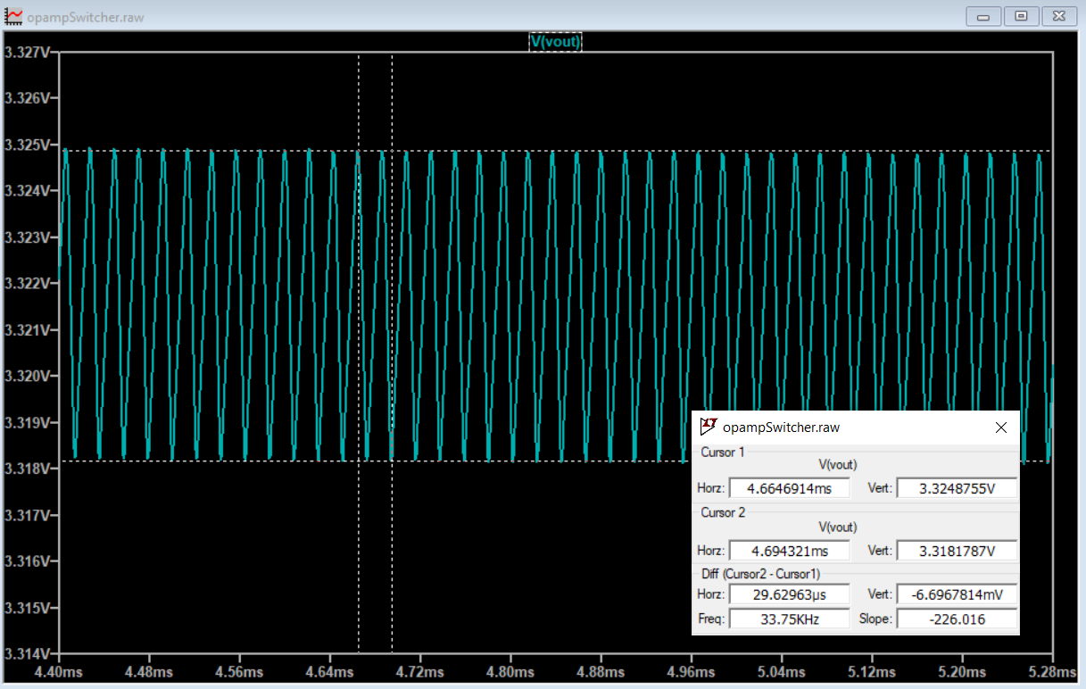
And less than 7mV of ripple:
![]()
Time to make it for real!
-
Single Supply Operation
04/19/2023 at 04:28 • 0 commentsA little breaking out of the maths for the Schmitt Trigger allowed me to move the thresholds from +/- voltages to all positive voltages. And then I needed to shift up the integrator reference as well, by adding R7 and R8.
![]()
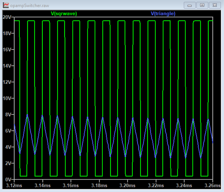
![]()
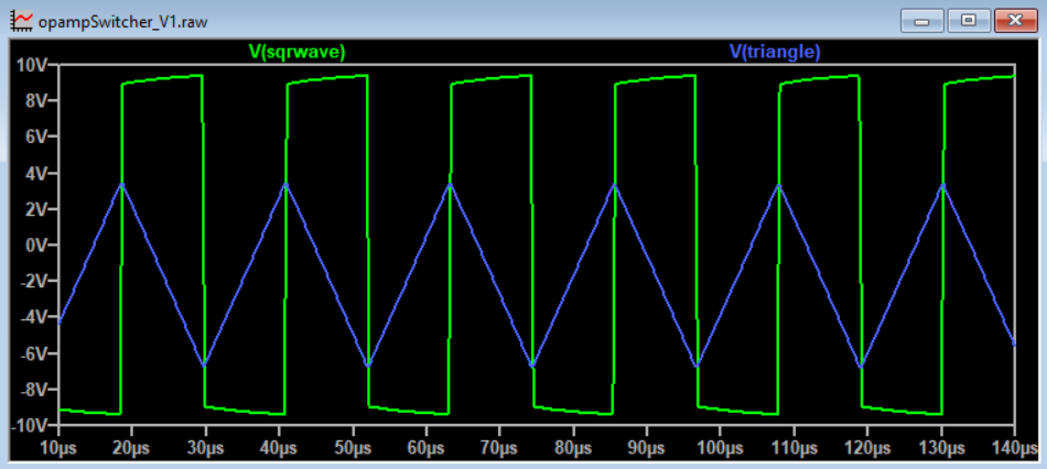
Now we're cooking! Rail to rail square wave output, integrated triangle wave, all on a single supply.
Next stop threshold output from the triangle wave, gives us a fixed PWM.
-
TI's appnote
04/19/2023 at 04:10 • 0 commentsIn the original contest announcement comments, someone mentioned that TI had a great opamp guide, so I decided to check it out.
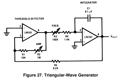
Inside, it too had a section on making a triangle wave generator, which is a fundamental piece to making a PWM.
![]()
The output of this circuit gave a much better square wave feeding into the integrator, and actually went rail to rail. However it still required a dual power supply.
The first opamp is a Schmitt Trigger circuit used to make a square wave. The square wave is then integrated by the second opamp circuit, which produces a triangle wave. The integrator is an inverting type, and its output is then fed back to the Schmitt Trigger to cause it to toggle as its thresholds are crossed.
All that was left to do was to have the triangle output feed into a variable threshold detector and we have PWM action! Followed by making all this work on a single supply.
-
Broad Overview of a buck regulator
04/19/2023 at 03:58 • 0 commentsFirst I started with the major building blocks of a buck regulator:
- Oscillator
- PWM
- Feedback
Poking around on the googles for opamp PWM, I ran across this great video series: Op-Amps, PWM
I quickly fired up LTSpice and simulated the circuits. It did work, but the waveforms were a little too off for my tastes. And, more importantly, it required a dual supply to operate.
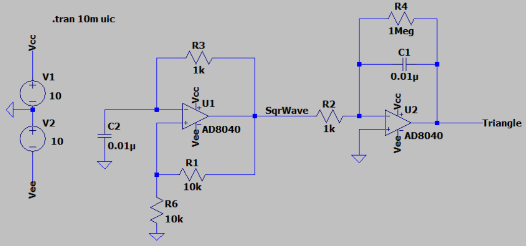
Basic operation is as follows:
The first opamp is a oscillator circuit used to make a square wave. The square wave is then integrated by the second opamp circuit, which produces a triangle wave.
![]()
![]()
The search continues...