 Rudraksha Vegad
-
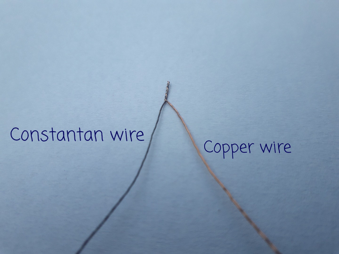
1Making the Thermocouple ( T- type)
Gathering materials:
I chose to make T- type thermocouple since thats the thermocouple i found that was easy to make out off scrap and materials which are easy to find.
is made using some salvaged constantan wire off of a power resistor and enameled copper wire form old motor.
I'll explain why enameled copper wire is used
in modern power resistors sometimes nichrome wire is used but after observing the performance of thermocouple and calculating the sensitivity of the thermocouple ,it was clear that the wire i got from that resistor is constantan and not nichrome ! (or maybe its nichrome, but its performing the same).
![]()
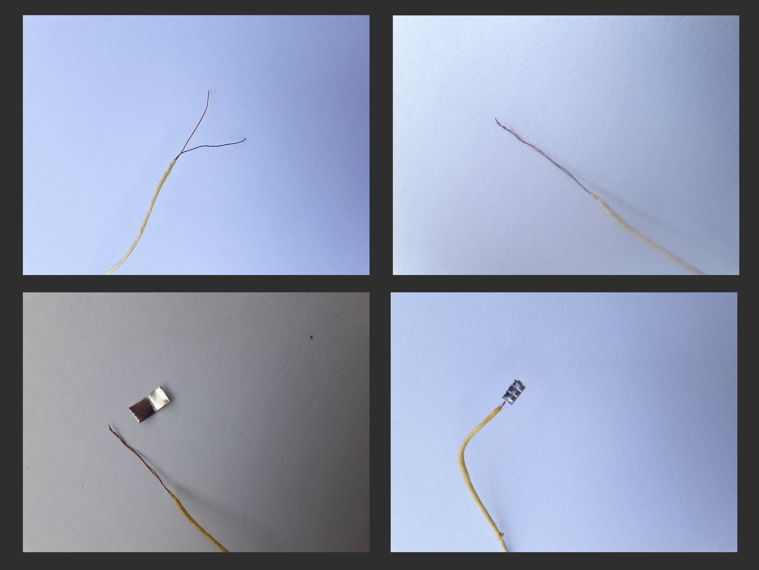
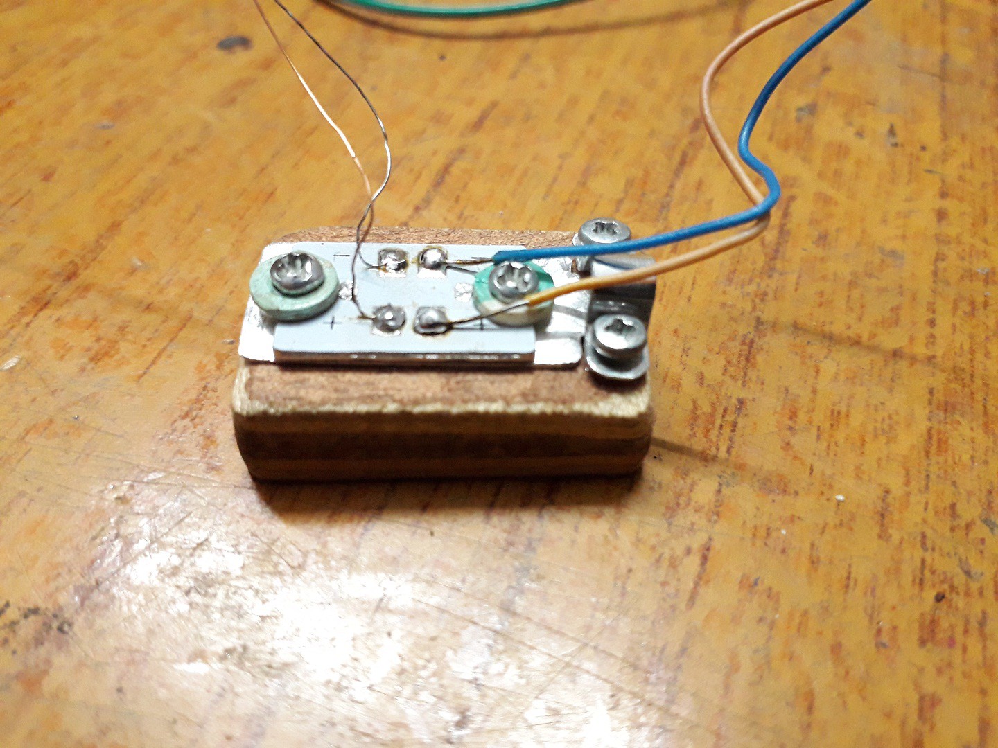
Making it permanent and durable:
The enameled copper wire is stripped from the end and twisted with the constantan wire and then with a makeshift spot welder ! made out of a 12 V transformer with carbon electrode from a battery I spot welded the twisted ends of thermocouple.Now since the copper wire is enameled both wires are twisted to a length and then wrapped with plumbing Teflon tape ( the yellow tape in the pictures below )
![]()
To make it durable a small piece of aluminum sheet is crimped over the twisted end.
The aluminum strip is also there to increase the area of contact of the thermocouple tip.![]()
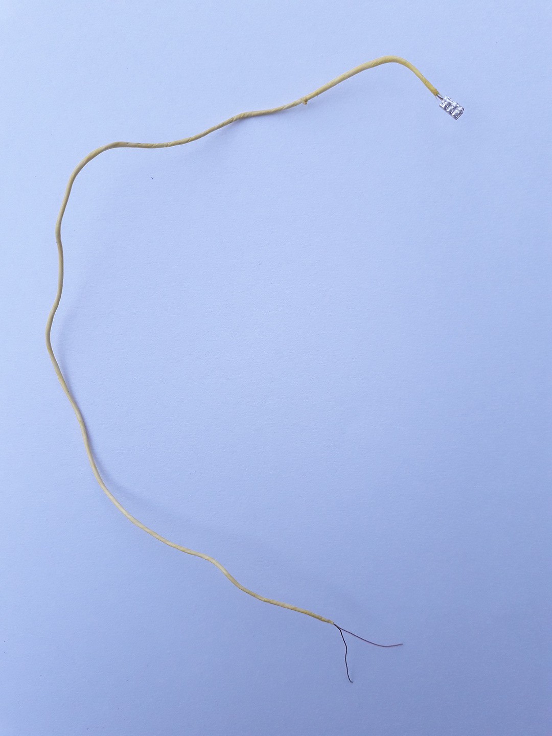
There we have the T type thermocouple ! -
2Rough Idea of building the circuit
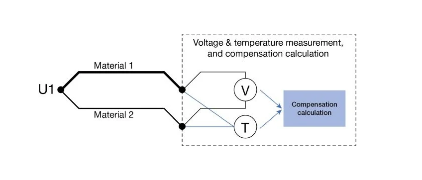
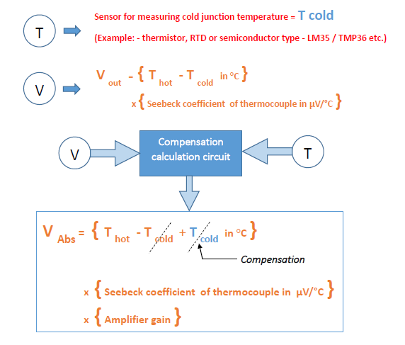
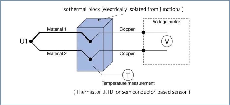
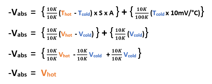
First lets see whats the logic and working of cold junction compensation :
![]()
Thot = Temperature of the hot/measuring junction
Tcold = Temperature of the cold junctions
Cold junctions are kept in a isothermal block and the temperature of isothermal block is measured i.e. T in the picture below
Voltage Vout is without amplifier Vout = (Thot - Tcold) x S ....... i.e V in the picture below![]()
To compensate the effect of the cold juntions , we add the previously measured temperature of the isothermal block T(which is in terms of voltage) to V as shown above and by doing this we neutralize the effect of cold junctions and get the final absolute reading Vabs of the temperatue being measured at the measuring junction.To understand this I took help from these lectures, they are very usefull . You all can check them for more insight: (not my channel)
> Hardware design lecture
> Industrial instrumentation lecture
> Casual talk on Thermocouplesexample to understand:
lets say temperature at measuring junction is 180°C ( at U1 in above diagram) and lets say our circuit is operating at room temperature say: 28°C (that will be also temperature of the isothermal block)
S - > Seebeck coefficient ( sensitivity of thermocople )
We are using T type thermocouple so S = 42.79µV
A -> Amplifier gain (assuming amplification is a such that output is in terms of 1mV/°C)
A= 23.3
( i'll explain how to calculate Seebeck coefficient and Gain in step 4 )Now WITHOUT COMPENSATION if we only use AMPLIFIER
output will be :
Vabs = { Thot - Tcold } x S x A
Vabs = { 180 - 28 } x 42.79µV x 23.3
Vabs = { 152 ] 42.79 x23.3
Vabs = 6.504 mV x 23.3
Vabs = 151.54 mV .............. [Wrong measurement ]Now WITH COMPENSATION and AMPLIFIER:
output will be :
Vabs = { Thot - Tcold + Tcold } x S x A ................ [ Compensation ]
Vabs = { 180 - 28 + 28 } x 42.79µV x 23.3
Vabs = { 180 ] x 42.79µV x 23.3
Vabs = 7.7022 mV x 23.3
Vabs = 179.4mV ≈ 180mV ................ [Correct measurement ]There's also a different way to do this and we'll use this method:
Above method is correct, but is difficult to implement practically. Now ,here we add the compensation voltage after processing the thermocouple voltage.
This is much easier and since the lm 35 already has sufficient sensitivity no need to amplify it.Vabs = { Thot - Tcold } x S x A + { Tcold x sensitivity of cold junction sensor }
( In this project sensitivity of lm35 = 10mV/°C )
Vabs = { 180 - 28 } x 42.79µV x 23.3 + { 28 x 10mV }
Vabs = { 152 x 42.79µV x 23.3 } + 28mV
Vabs = 151.54mV +28mV
Vabs = 179.4mV ≈ 180mV ................ [Correct measurement ]Thats Idea so lets start implementing it practically and design the circuit in parts and understand each part...
-
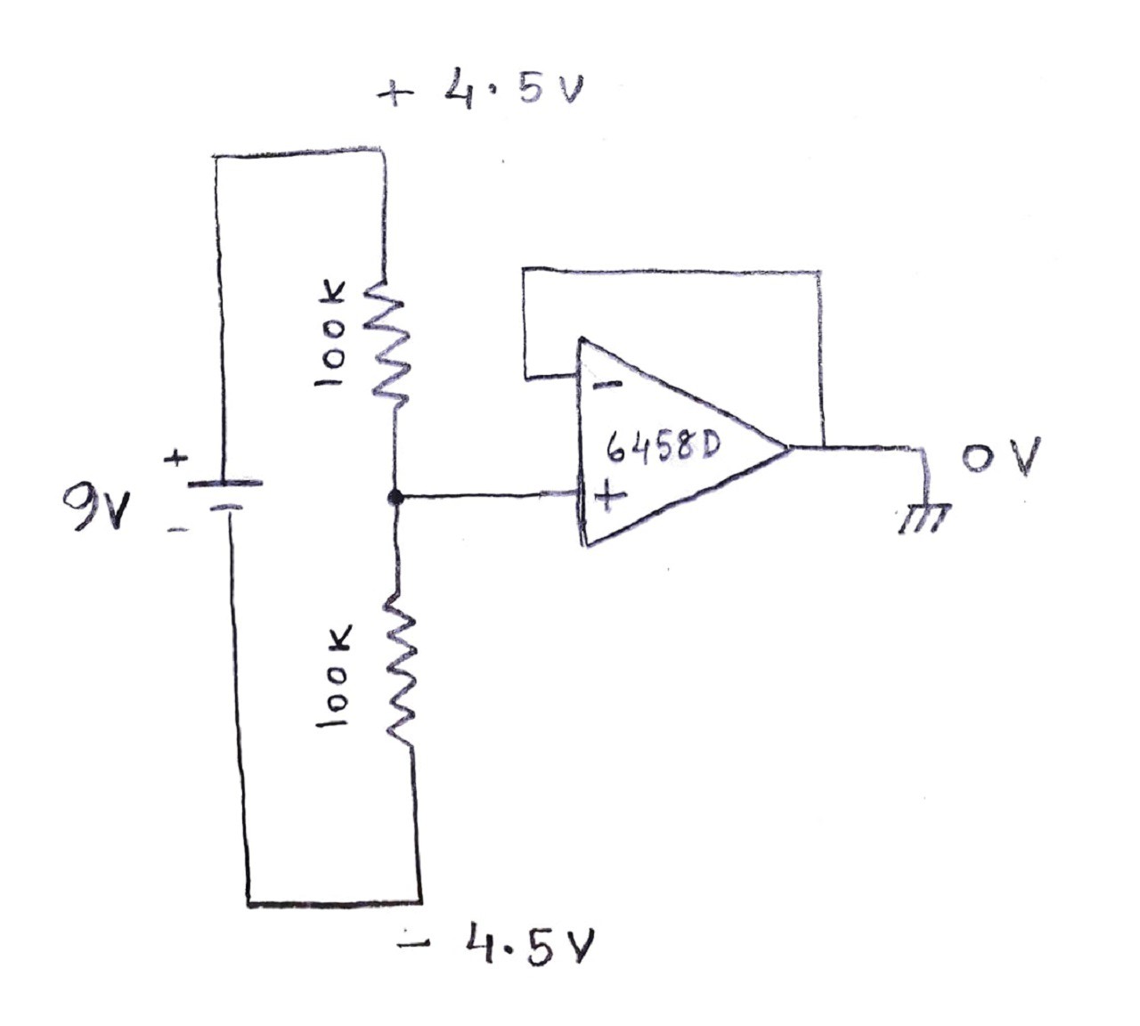
3Split power supply
For powering the whole circuit , a standard 9V battery with a resistor divider and op-amp based split power supply is used ,providing + 4.5V, 0V and - 4.5V voltage rails.
![]()
An op-amp (nothing specific about 6458D i just had one salvaged so i used it) is used to buffer the middle point of voltage divider thus giving a buffered ground reference i.e. 0 volts as shown above.
-
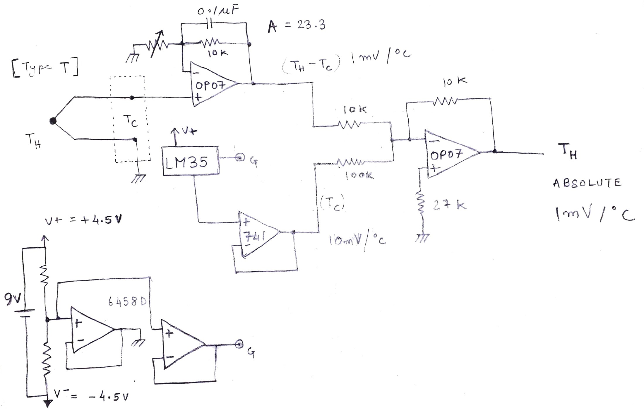
4Circuit for amplifying thermocouple miniscule voltage, calculating S & A
Normally without any amplifier the output from the thermocouple is in µV range.
We need to amplify this voltage so that its easier to understand and read.
A simple non-inverting amplifier configuration is used to amplify the miniscule voltage of the thermocouple and output a readable voltage directly proportional to the temperature being measured precisely 1mV/°C.To find the gain, There's a formula :
A = required output per °C / Seebeck coefficient of T type thermocouplewhat is Seebeck coefficient :
This is the sensitivity of the thermocouple, i.e. it explains how much voltage is generated per temperature change. Different type of thermocouples have different sensitivity.
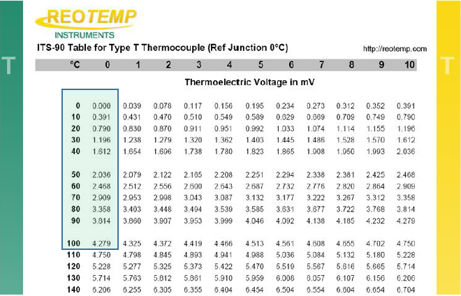
To do that first we need to know how to find Seebeck coefficient of type-T thermocouple
There are many look up table from which it can be calculated. Here’s how –
link for for the table and other types of thermocouple - > Thermocoupleinfo
here's a screenshot of the part which we need...
![]()
Look at the blue highlighted box in the above table:Thermoelectric output voltage without any amplifier at 0°C = 0 mV
Thermoelectric output voltage without any amplifier at 100°C = 4.279 mV
Therefore Seebeck coefficient 'S' = 4.279 mV / 100°C
Seebeck coefficient 'S = 4279 µV / 100°C ....... { 4.279mV = 4279 µV}
S = 42.79 µV / °C
So to design a amplifer so that it amplifies 42.79 µV / °C into 1mV / °C we need to calculate the gain.we Know the formula we discussed earlier:
lets see how to deign a amplifier to achieve 1mV/°C output.
A( gain ) = 1mV / S
{I chose 1mV just a choice ,if you want output in terms of 10mV/ °C use 10mV}
A = 1mV / 42.79 µV
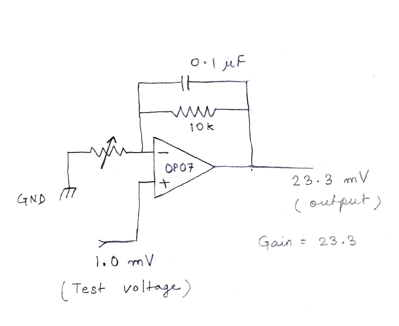
A = 23.3here's the circuit i came up with after testing it on the breadboard :
OP07 is used because of its low input offset voltage. Any general purpose precision op-amp will also do the job.
![]()
There's a 0.1 µF ceramic cap across 10K resistor to stabilize the gain and to calibrate the the gain precisely i gave a test input voltage of 1mV (1.0mV precision) input and i kept turning the trimpot untill i got 23.3mV output.
here's a link on how to design non inverting amplifiers - > TI non inverting amplifiers
-
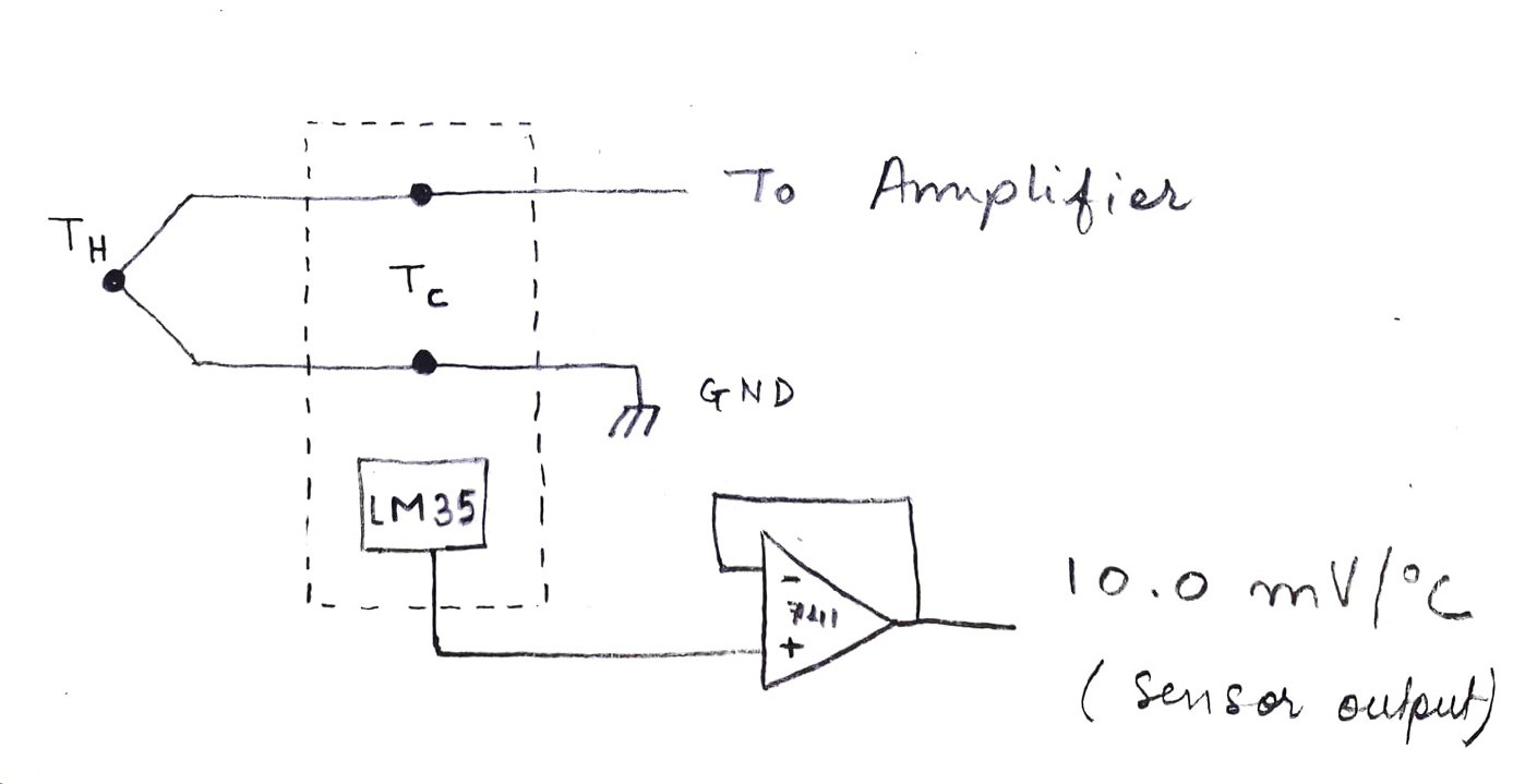
5Designing the Isothermal Block
The purpose of the isothermal block is to couple the cold junctions thermally coupled and allow us to measure the temperature of the cold junctions.
![]()
As you can see above the cold junctions are kept in a isothermal block.
Lets see how to implement it practically -
I used an led strip with aluminum backing for isothermal block. Since this strip already has what i need in an isothermal block.
The contacts in the led strip are " thermally coupled but electrically isolated ". That's exactly what is needed.
I also made a U shaped clamp to hold the LM35 firmly in contact with the aluminum backing of the strip. Some thermal paste was also used to make sure of thermal conductivity between the parts.
![]()
Here's the schematic -
![]()
the LM 35 is a bit sensitive and fragile part so just for security i added a buffer.
-
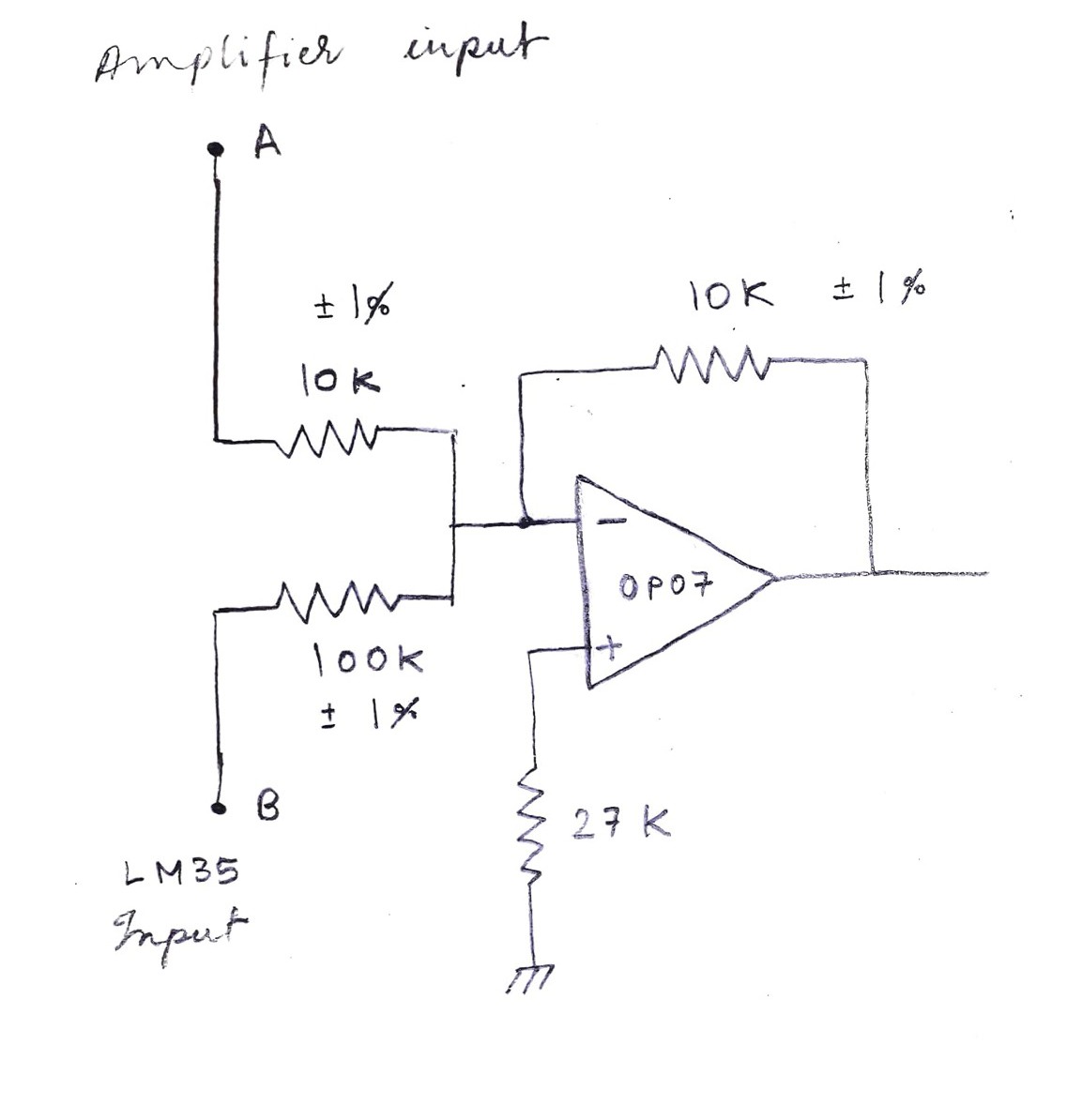
6Summing Amplifier
Now as I discussed earlier about compensation we need to ADD the amplified output and the output of the measured temperature of Cold junctions we need a summing amplifier.
Lets see how to design it.
I chose the inverting summing amplifier because is very simple as compared to the non inverting one.
Here's the circuit after testing it on breadboard-
![]()
A is the wire which accepts the amplifier output designed previously.
B is the wire which accepts the LM 35 output.
Notice that its not symmetric , i mean the input resistors are 10K and 100k thats because the non inverting amplifier's output is in terms of 1mV/°C and the LM35 output is in terms of 10mV/°C so to balance that out those resistors are chosen .(Handpicked 1% tolerance resistors for precision)
The summing amplifier adds and gives the absolute temperature in -1mV/°C
-
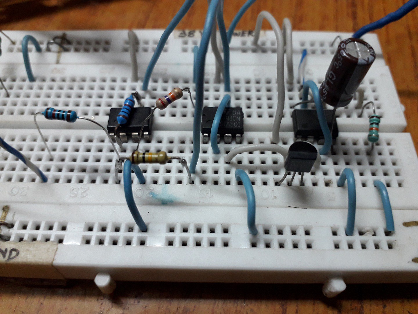
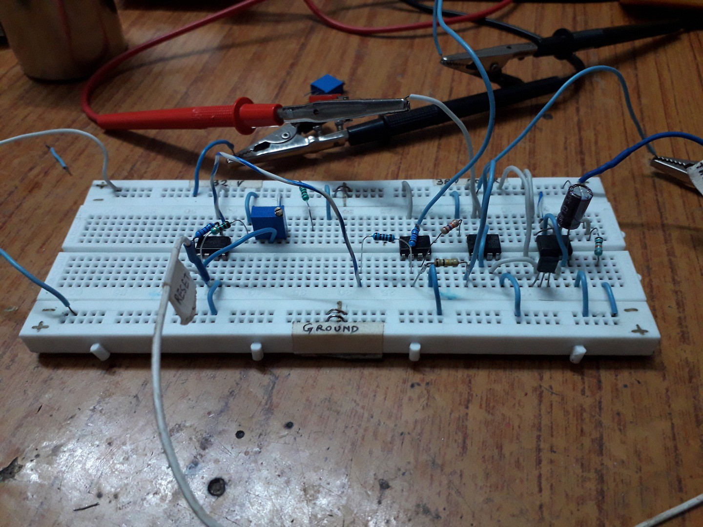
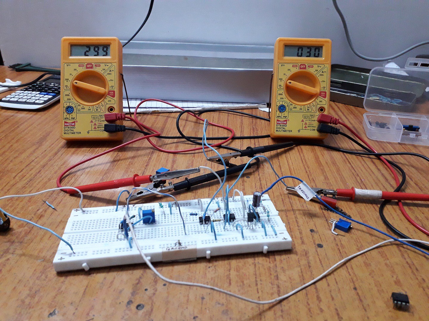
7Breadboarding
I tested the complete circuit on breadboard
![]()
![]()
![]()
This is the complete circuit with combined parts:
![]()
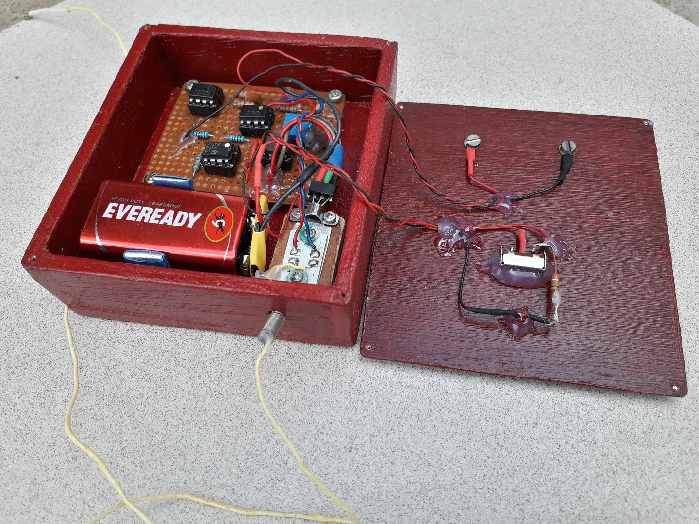
The whole circuit is powered by a 9V battery , a 3 V coin cell would be perfect but since the LM 35 needs at least 4 volts to operate and that too with a split supply so i chose a 9V battery. The circuit consumes (5.80 mA without the indicator LED) and (5.97mA with the LED indicator).
lets see what the circuit is doing through equation:
Vhot = Thot x S x A
Vcold = Tcold x S x A
also Vcold can be found out as:
Vcold = temperature sensed by LM35
'S' gets multiplies itself by the nature of the thermocouple no circuit need for it![]()
Now here as you can see the measured temperature of the cold juntion is outside the amplification part of the equation that's because the LM35 output is already amplified to a usable voltage i.e. 10mV/°C so The equation appears a bit different as apposed to the logic we saw earlier but its the same thing happening.
i have explained this in step 2.Note : I know the Vabs ( absolute temperature reading ) output is inverted i.e. - 1mV/°C , i could have inverted it again but i thought I'm going to connect it to the multimeter anyway so instead of adding a inverter i just flipped the wires (Swapping multimeter leads while taking measurements ) ☺ ! I was lazy here but if you plan to make one there's no harm in adding an inverter.
In the complete circuit i have again buffered the the ground where you'll see 'G' written, those two G's are connected with a wire , i did that because when i power the LM 35 it loads the whole circuit and messes up the output, i tried to experiment and i found that the LM35 needed a separate buffered ground and that solves the loading problem. I also tried using a high current op amp to buffer the resistor divider but that also didn't work . I'm not sure why that's happening, if anyone knows about that ,let me know ill be very grateful for the guidance.
-
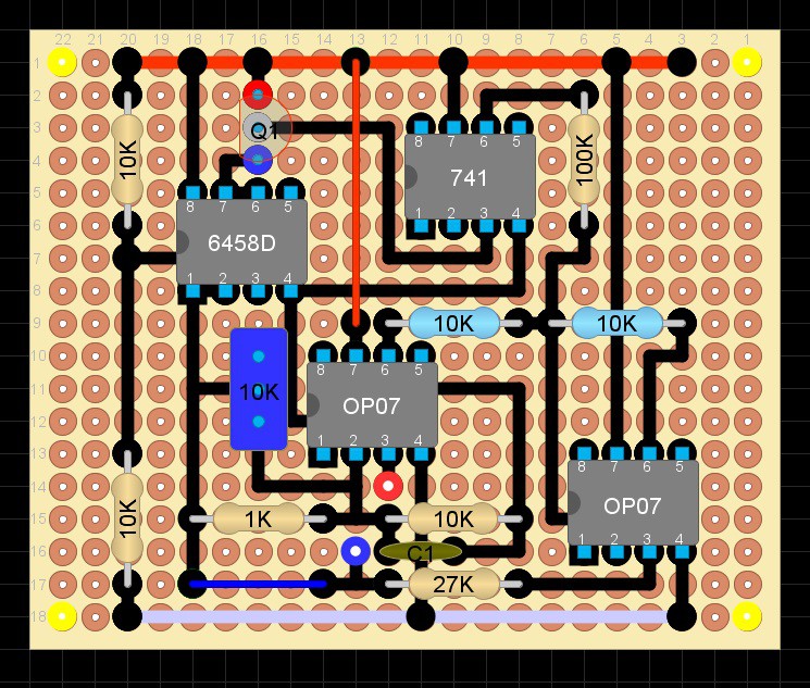
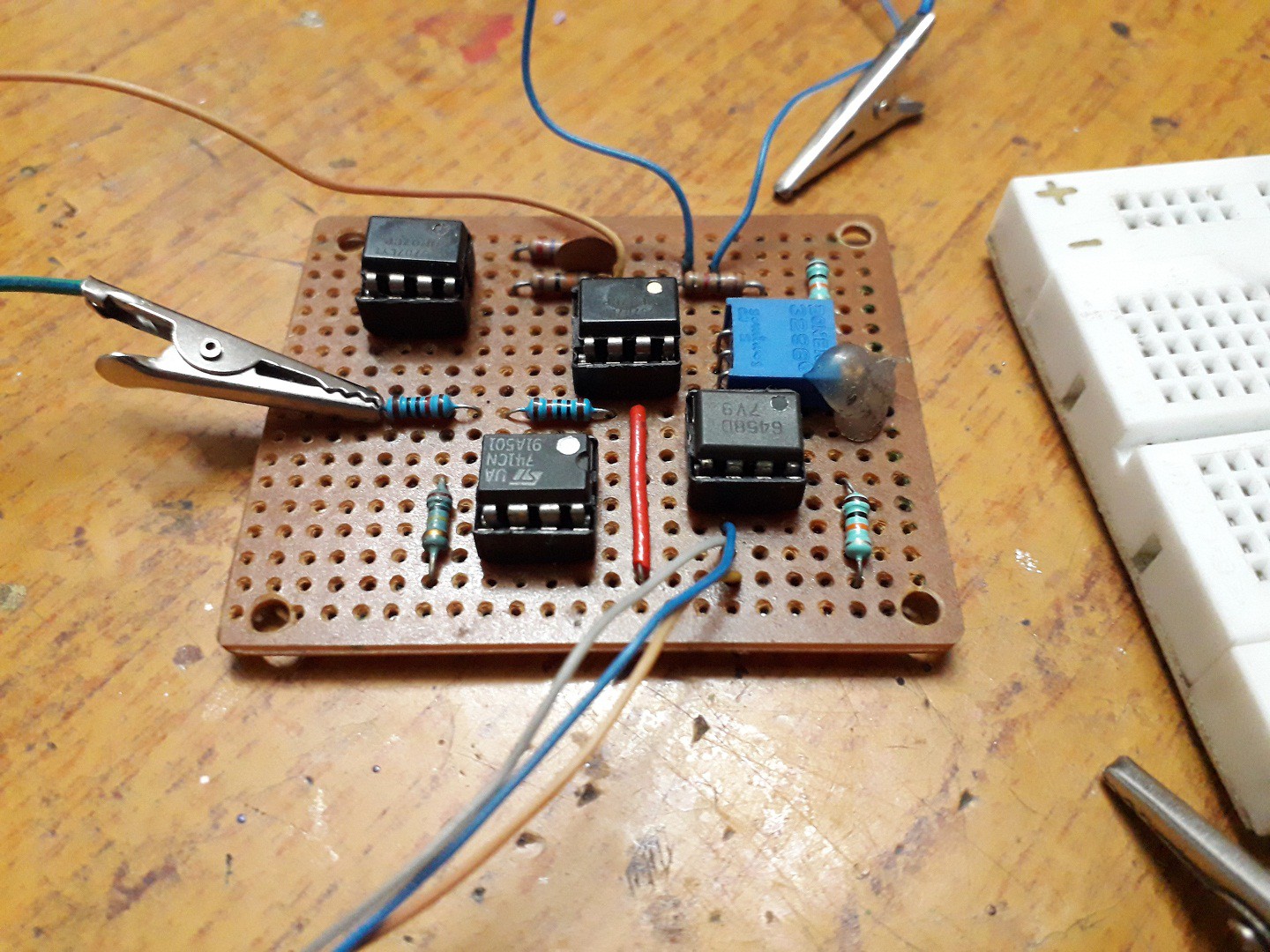
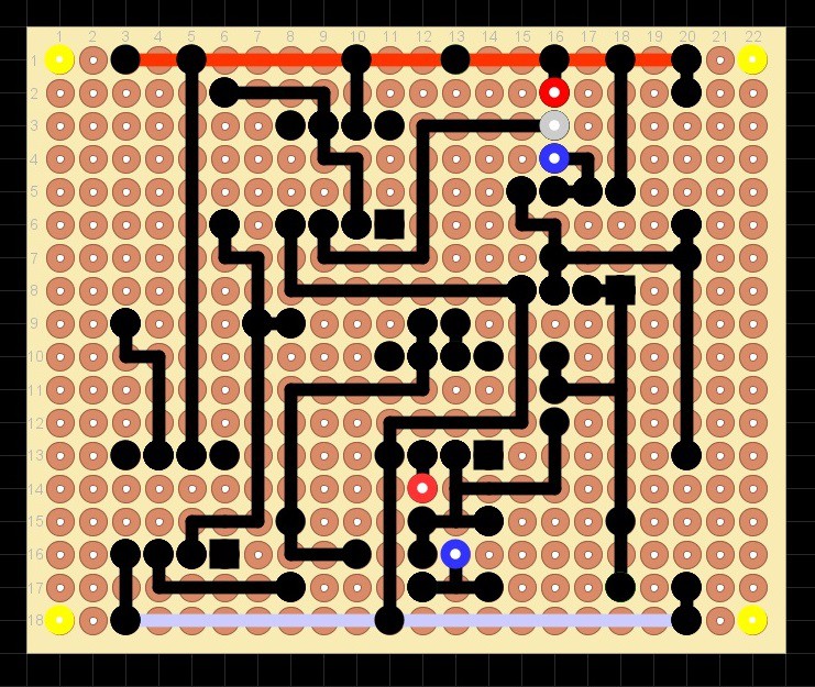
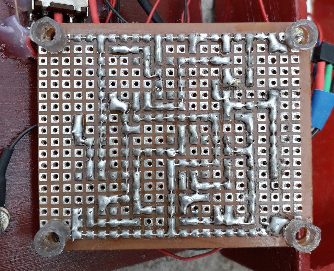
8Layout and soldering
I could have just soldered without layout ,but the circuit will be difficult to trouble shoot so i planned the circuit using free layout tool called DIYLC .heres the link for the layout creator (not my software) -> DIYLC
here's the layout i designed:
Front:
![]()
![]()
Back:
![]()
![]()
-
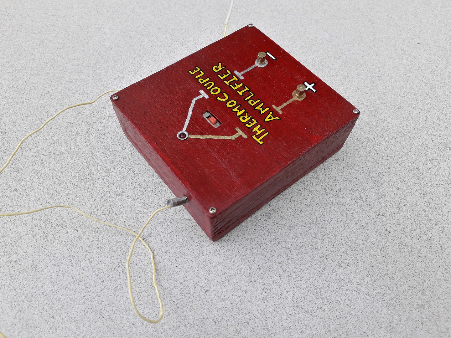
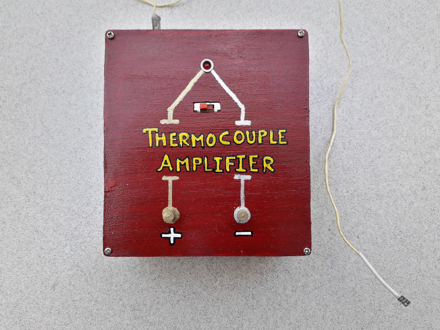
9Project enclosure
I made a Small box out of plywood to make to project permanent.
![]()
![]()
![]()
The + and - are spots to connect multimeter/mili-voltmeter probes and the switch is there to turn ON and OFF the whole circuit and i gave it a thermocouple shape art just for fun ☺!
Thermocouple Amplifier
Home made thermocouple and an analog cold junction compensator which gives output voltage directly proportional to temperature in °C
Discussions
Become a Hackaday.io Member
Create an account to leave a comment. Already have an account? Log In.