Mehrdad
-
Run Ubo App on Pi 4/5 - no additional hardware needed
06/04/2025 at 04:03 • 0 commentsWhat does it do?
Ubo app:
- offers a GUI (shown inside browser or hardware) to control your Raspberry Pi and Linux utilities.
- helps with setting up WiFi even if your credentials change after initial setup.
- gives your Pi virtual speakers, (and soon) microphones, and camera. That means, you can play audio on Pi without any audio hardware and hear the audio out of your phone/laptop speakers (virtual speakers). Same for mics and camera.
- lets you set up remote access (RPi Connect and VSCode Tunnel) using the GUI and configure different system/app settings, install Dockerized applications, etc.
Here's a quick example of installing a Dockerized app (e.g. Jupyter Notebook) in a few seconds:
It also offers a language agnostic API that you can communicate with from any programming language.
For example, with a few lines of code, you can show error messages or notifications on LCD screen, or get input from user with keypad (such as yes/no prompt), scan barcode, etc.
Here's an example in typescript.
![]()
Why should I care?
You can easily run this on your Raspberry Pi and make it portable and easier to use for self-hosting apps or development. Specially if your application requires audio, video, user interaction, sensor readings, etc.
If you are working on a code written on any programming language other than python and your program needs to interact with some hardware/UI, this would be a life saver.
We are not introducing our own OS. The app runs in user space and installs on the latest Raspberry Pi OS (with latest linux kernel 6.12.25).
Ubo app is fully open source and free. If you like it, please consider supporting our efforts by making code or coffee contributions.
Let's set it up. Is it hard?
![a man in a suit and tie is smiling while standing in front of a bar with bottles of alcohol .]()
Do you have MicroSD card and reader? Then no. All you need to do is to download the lite or full image from the release section under GitHub repo:
https://github.com/ubopod/ubo_app/releases
To flash the image onto a MicroSD card, follow the steps here:
https://github.com/ubopod/ubo-image
You can follow the steps in the video below to use Ubo app right away:
You can also run the installer script under repo readme if you would like to install it on your existing OS.
One thing to note here is that not everything can be emulated in software. To use hardware specific features, such as working with sensors, infrared receiver/transmitter, etc you need to use Ubo pod or add your DIY hardware.
Vision
The vision for Ubo Project is to create a unified human computer interface. An everything app in a sense where users can easily interact with computers through simplified multi-modal UX.
We are working to bring control through natural languages through LLMs and Ubo MCP server.We would love to be able to do (almost) everything on-device and offline.
What makes this unique
I would say this deserves a separate post since there's a lot to say on this topic.
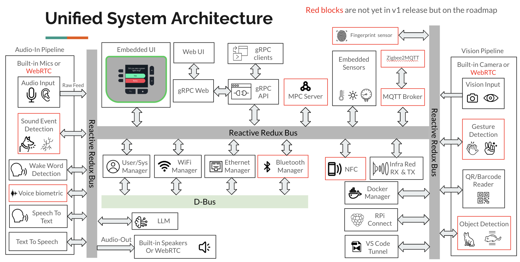
The underlying software architecture implements a centralized state store with a Redux-based message bus that connects services, processes, and user interfaces. The system follows reactive and event-driven design patterns.
The diagram below shows the high-level block diagram of the system architecture.
![]()
-
Ubo Software v1.0 Debut
12/06/2024 at 06:37 • 0 commentsThe development of the software stack has been a one year+ long intense project with so many details and decisions. The v1 release is a smooth UX for headless operation. This is a heavily design-driven project with the goal of removing technical barriers and complicated shell commands with a polished UX.
Before I get into the software architecture design, let's watch a short demo
Ubo Pod and its SDK
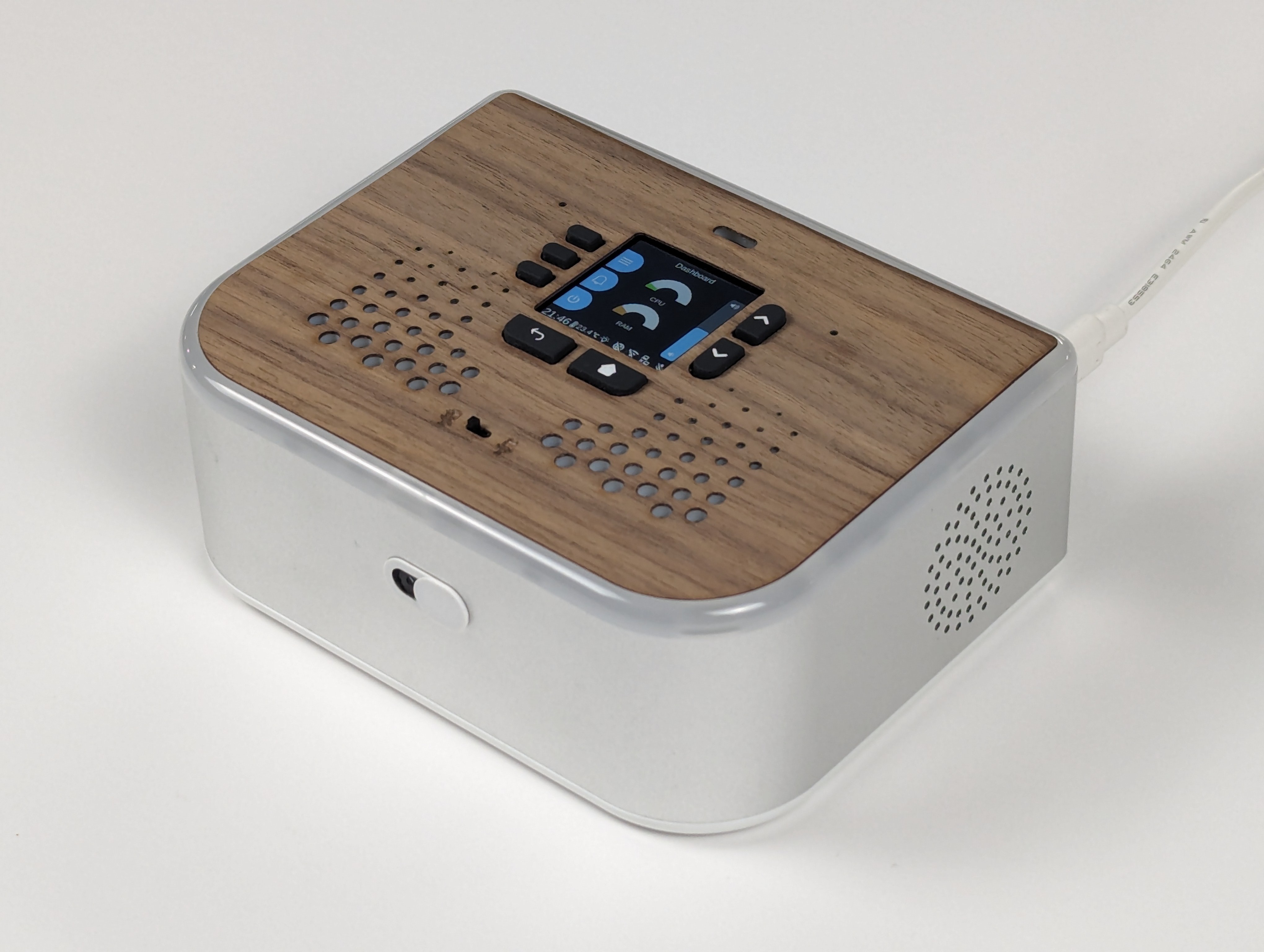
What is Ubo Pod
Ubo Pod enables developer communities to bring openness, transparency, and privacy to the device ecosystem.
It has an LCD screen, a camera, a microphone, a pair of speakers, a set of buttons, some sensors, an LED ring, and a Raspberry Pi 4 inside. All the inputs and outputs on the Ubo Pod case are connected to the Raspberry Pi 4 through a custom PCB.
So it is basically a light weight, portable, and open-source computer that doesn't need a monitor, a keyboard, or a mouse to interact with it.
On the upcoming model that supports Pi 5, you can connect AI accelerators like Raspberry Pi AI Kit and Google Coral USB Accelerator to the Ubo Pod to run machine learning models on the edge to have your own AI assistant.
My goal is to support future models that support Pi 5 and beyond and keep support for model 4 until the end of life of the Pi 4.
![]()
Vision
We want to create a platform that is open, transparent, and respects the privacy of its users. So everything including the hardware as well as the software is open-source. Any proprietary element is opt-in. We believe that the Ubo Pod can be a great tool for developers to create applications that are not possible on other platforms. We want to create a community around the Ubo Pod that will help us to achieve this vision.
Ubo App
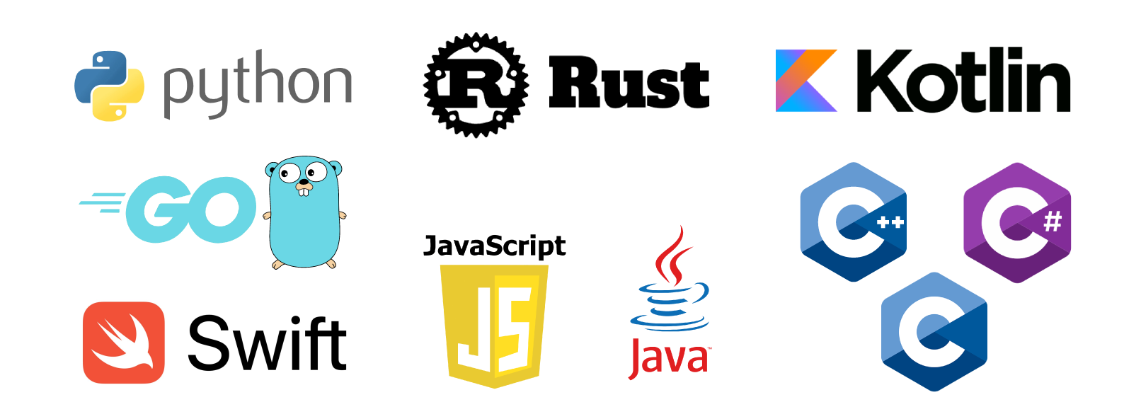
Ubo App is a Python library that allows you to interact with the Ubo Pod. It is compatible with Python 3.11 and above. It exposes its API to other programming languages via gRPC. So you can easily integrate with it from many programming languages including JavaScript, Python, C++, Rust, Go, Ruby, Java, etc. It includes an SDK for developers to create their applications for Ubo Pod as well as a runner app that hosts those applications.
High Level Functionality
Ubo App is designed to allow a less tech-savvy or lazy tech-savvy user to perform typical system admin tasks with ease. Here's a quick video showing some of the features:
Networking
Using the graphical user interface, you can add/delete WiFi networks (pass credentials either through QR code or Web UI), make the device a WiFi hotspot, get interface IPs, and other network related tasks.
Remote Access
Ubo Pod also helps you setup SSH, Raspberry Pi Connect, VS Code Tunnel to remotely connect to the device all without ever using a keyboard or a mouse.
System Management
You can add/remove user accounts, give users sudo access, change user passwords, and install/enable desktop environments.
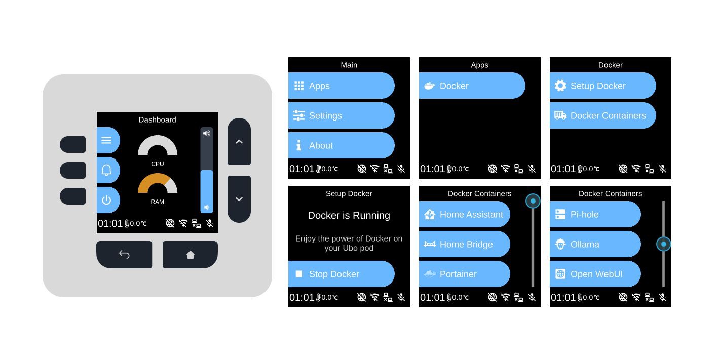
Install Third Party Apps
The app lets you install and run Docker containers and run multi-container apps with Docker Compose. You just need to provide the Docker Compose config file (and other required files) and the app will take care of the rest.
![]()
Other featuresYou can check software version and update the device software via the graphical user interface.
Getting Started with Ubo App
Follow the installation instructions here to install it on your Ubo Pod. In case you don't have access to an Ubo Pod yet, you can follow the instructions provided here to set up a development environment on your computer. You can write and test your applications on your computer before deploying them to an Ubo Pod.
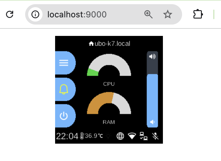
Our next software milestone in Version 2.0 is to release a virtualized Ubo Pod in your browser so that software and hardware components can be emulated. In that case, you can also use the software on a bare Raspberry Pi.
![]()
Core Design
Ubo App has a lightweight core. It is designed to be modular and extensible. It is composed of several modules named "Ubo services" or simply "services" that are responsible for different parts of the system.
Anyone can write a new service and plug it into the system on their own pods or share it with the community.
Ubo App runs on top of a redux-like store. It is a single source of truth for the whole system. Each service can subscribe to the relevant parts of the store and react to changes.
Reducers in the redux implementation used in Ubo App have the extra capability of returning a list of side effects.
The Core Menu Structure
The core mostly consists of a nested menu in the middle and a narrow footer in the bottom. The core only implements these menu items:
- Main Menu
- Apps Menu
- Settings Menu
- About (Lets the user check the version of the Ubo App, and update it if a new version is available)
- Notifications
- Power Menu
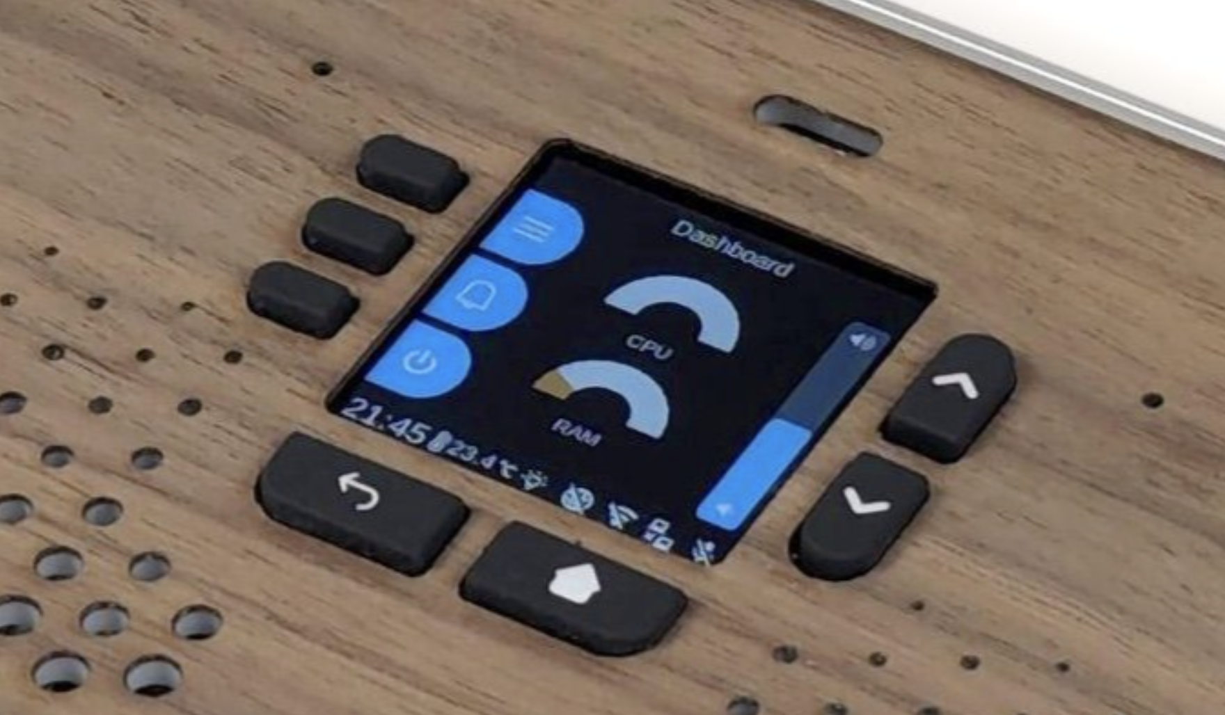
The footer renders a clock next to temperature and light sensor readings on the left and a set of status icons on the right. The core doesn't provide any status icons itself. It is up to the services to register their own status icons or use icons from nerdfonts.com which is supported by the core.
![]()
Ubo Services
Each service can register one or multiple icons in the footer and/or register one or multiple menu items in "Apps" and/or "Settings" top-level menus. The user will be able to interact with the modules through these menu items.
The Menus
Conclusion
In this post, we introduced you to the Ubo Pod and Ubo App. We explained the vision behind the project and how you can get started with Ubo App. We also explained the core design of Ubo App and how you can write your own services for it.
Upcoming Posts
In the upcoming posts, we will dive deeper into the Ubo App and its SDK. We will cover topics in these areas:
- How to write your own services/application and plug them into the Ubo App
- Core design of Ubo App and how it works
- The challenges we faced while developing Ubo App and how we solved them
- The future of Ubo App and how you can contribute to it
We are excited to see what you will build with Ubo Pod and Ubo App. We are looking forward to your contributions to the project. If you have any questions, feel free to create an issue in the Ubo App repository.
To obtain an Ubo Pod, please subscribe and follow our upcoming crowdfunding campaign on Crowdsupply.
- Main Menu
-
GUI Design
08/03/2023 at 05:31 • 0 commentsUbo Simple GUI Software Architecture
In this document, I propose and discuss basic design principles behind Ubo GUI architecture and the driving forces behind certain decisions. This is a work in progress and this document is solely offering insights and proposals on the design. I would love to hear your thoughts and any suggestions on how to best design the UX.
The main objective behind Ubo GUI design is to offer a simplified graphical interface to the application developers so that they can easily understand and use it within minutes.
In order to accomplish that, we need to offer a very simple API and data abstraction layer as well as a set of examples that can serve as starting points for developer applications.
Simplicity must be followed in every aspect of the design (window manager, API/Interface, templates, etc). By physical design (LCD size, keypad design, etc), this GUI is only intended for simple interactions, and is not indeed to replace a desktop or mobile-like experience.
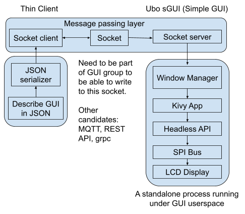
The picture below shows a high-level architecture of the proposed GUI design:
![]()
Figure 1. Proposed GUI High-level software architecture
From developers perspective, they only need to understand the JSON data structure to describe their GUI layout and function. The rest is handled by the GUI processor and the developers do not need to necessarily learn what is happening inside the GUI processor service. However, if the developer wishes to define a new GUI experience that is not offered by the SDK out-of-the-box, then they will need to dig deeper and understand the design logic and architecture of the GUI software.
As depicted in Figure 1, the proposed GUI software architecture consists of a server and clients. The server is constantly listening on a socket and whenever a client (user application) wants to interact with it, it will send a JSON object to the server. The server can also respond if certain actions are performed on the registered callback. The details of server/client implementation (what type of server/client to be used) have to be determined.
This can be implemented via POSIX socket, simple REST API, MQTT, etc.
The advantage of this server/client design is that multiple applications can send data to the display (for example, error messages, notifications, etc)
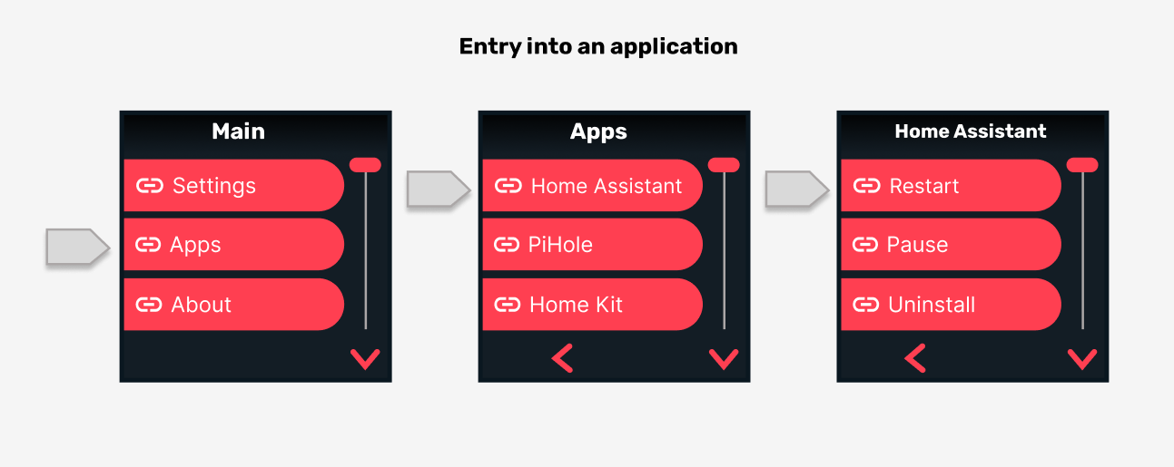
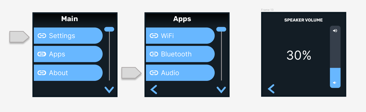
The system application will own and manage the flow of the GUI and will offer an entry point for foreground user applications. However, when applications run in the background, they would still be able to send notifications, show error messages, etc. Below is an example of entry into the application menu through the system menu.
![]()
Figure 2. Nested Navigation. System navigation can connect to app navigation
The GUI will offer the following pages and modes of interaction:
1.1 Home
The home screen is the default screen of Ubo. It is usually the landing screen after boot-up. The home screen includes a notification bar on top (or bottom) as well as some shortcuts to show some information digests or access certain items such as the opening system menu (similar to taskbar experience).
1.2 Navigation
This is the main mode of interaction with the GUI. By pressing the buttons on the keypad, the user can navigate through a linked list of items with leafnode corresponding to informational items or an action. For example, an item can initiate an action, be on/off toggle switch, or just display some info such as software version. Each application can define their own navigation instance (which would include actions and information unique to that application). App navigation can be accessed through system menu/navigation as shown in Figure 2.
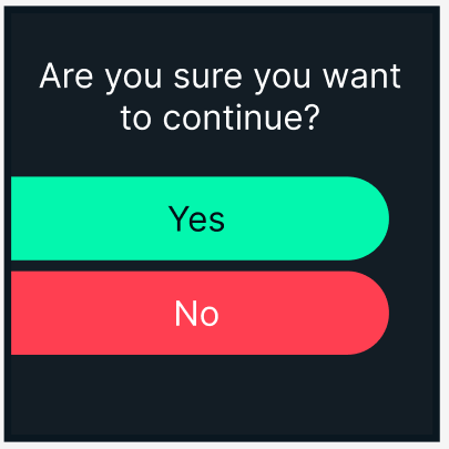
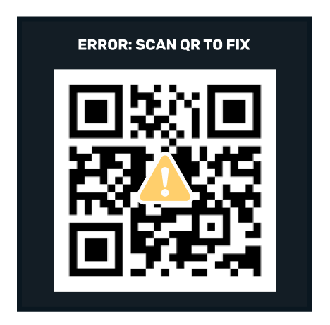
1.3 Notifications and prompts
User applications must be able to show notifications and prompts to the end-user when necessary. Here's an example of prompt:
![]()
The window manager needs to understand the urgency and priority of these messages and current state of the GUI and make a decision to show the message immediately or queue it for a more suitable time to show.
In addition, the user application can claim space on the notification bar on the home screen as a shortcut.
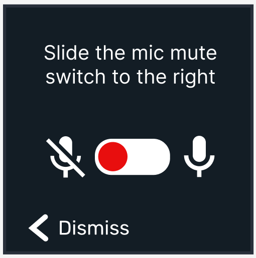
1.4 Dedicated screens
For example, you can enter a custom landing screen that uses up/down arrows to adjust certain settings or have a completely custom interaction. For example, the volume control screen shown below can be accessed through system navigation under settings. The screen utilizes the up/down buttons to adjust the volume. These screens must have a return point (example: back to exit).
![]()
Below are some other examples of dedicated screens:
![]()
![]()
2. GUI API
The GUI logic must encapsulate keypad functions and manage the GUI states internally. It should have a routing and window management functions built-in to decide what screen to show next and on what screen to return back to.
The GUI API receives a JSON object as input and returns a response with registered callback functions to apps for initiated actions inside the GUI. Certain screens have defined built-in behavior; For example, notifications all have a dismiss action built-in that is attached to the BACK button. If the user does not press any buttons, they will time out and get dismissed automatically. A custom shortcut can be designed to allow accessing “Pending Notifications”and clearing them.
2.1 Window manager
Window Manager's job is to properly process requests coming in from applications by using stacking and queues. For example, a queue can be used for notifications coming from apps that will be displayed to the user in the order they arrive.
2.1.1 Priority concept
Notifications or messages (such as prompt) that may overwrite the screen can also have a priority attribute that puts them in front of those with lower priority. For example, critical error messages can have a higher priority. Window manager should also keep track of what GUI is currently displaying. For example certain screens have an indicator that no other screen can show another screen over them (non-overridable). For example, if the user is browning the system settings, applications must not be able to show a prompt while the user is in the settings section.
3. Kivy Layout Design
In this section, I wanted to propose some design guidelines for pages/screens in the GUI.
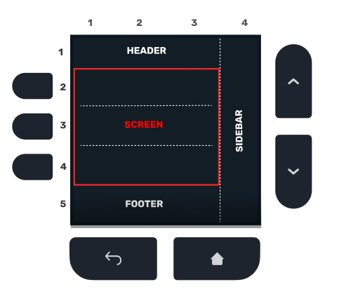
3.1 Navigation
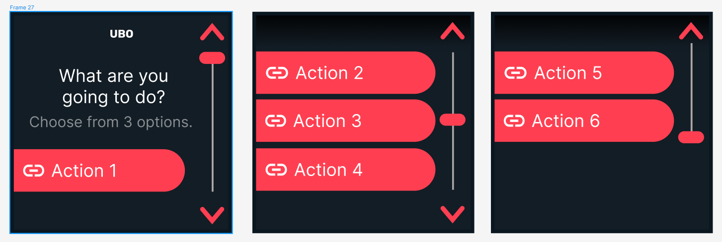
The design below suggests a layout for navigation pages. The screen is laid out in different sections: The top is the header that typically holds the page title. The page title does not change during scrolls through paginated lists. The sidebar holds the scrollbar. The footer can show the back arrow or footer text. The middle section can hold three list items and is designated as a screen. The middle section will transition up/down to scroll through using the buttons on the right hand side.
![]()
Below is an example of scroll operation through a list of 6 items. During scroll, only the middle section that holds the list items transition up/down and the title and scrollbar stay in place:
![]()
The GIF image below a simplified implementation of scroll animation:
![]()
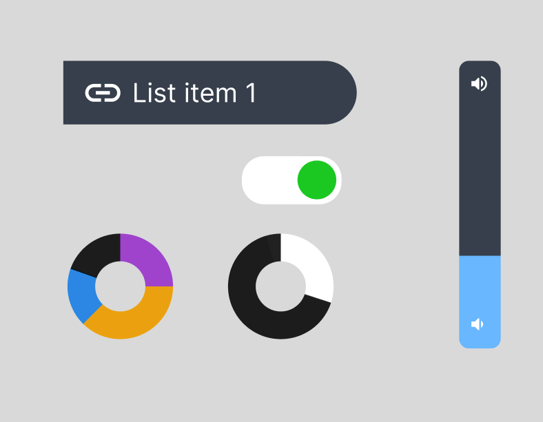
3.2 Widgets
We can also define a set of widgets that advanced app developers can use to quickly design their customs pages. Below are some examples of suggested widgets:
![]()
I would love to see what type of GUIs developers would like to see being designed. The figma board below includes the current design drafts:
-
LED Ring Design
04/25/2023 at 14:47 • 0 commentsIn this project log, I will discuss challenges I faced during the design and prototyping the LED ring feature of Ubo pod, things I tried, and the solutions I came up with.
In order to display notifications and visual cues at a distance I had decided to include an RGB LED ring to Ubo pod (similar to many other smart home product). This feature would allow developers to effective communicate notifications to users silently and catch user's attention.
Choosing the LED component
The first decision I had to made was which type of LED component I need to select.
I knew that using a non-addressable LED was not going to be a feasible choice here since in that case I had to deal with addressing them with another IC and routing 4 wires to each LED light would become a nightmare.
Therefore, I narrowed down my search to different types of addressable RGB(W) LEDs. The two main contenders were Neopixel and Dotstar LEDs. There's an awesome comparison of these types of LEDs posted by Adafruit on this page.
Since I needed to add a bunch of LEDs to form a full ring, the cost per LED was an important factor. I ended up putting 27 LEDs on the PCB!
I had previously used Neopixels in other projects and I had an inclination from the get-go to use them. However, there were a few things that bugged me about them and a few things that I liked.
Basically, the main cons for Neopixel LEDs were:
- PWM driver conflicts with RPi sound card
- Requires DMA and application requires super user privilege on Pi.
and the Pros were:
- One Data-In and Data-out line. Makes routing easier
- Very common and comes in variety of packages
- Low cost
On the other hand, DotStar LEDs had the following pros and cons:
Pros:
- No need for DMA and could be driven for regular GPIO pins
- No conflict with Pi audio
Cons:
- More expensive than Neopixel LEDs
- Less variety and options for packaging
- Routing 2 Data-in / Data-out lines would take more space
The cost factor and the existence of more packaging options finally convinced me to stick with Neopixel in my design, specially since I was adding a separate audio driver chip for HiFi audio and was not relying on Pi low quality PCM audio moving forward (considering on-board soundcard conflict issue).
Next challenge: Light Diffusion
This was a seemingly easy task at the beginning, however, a special design constraint turned it into one of the most challenging optical design work that I had undertaken before. The design constraint was to: diffuse RGB LED visible light to remove hotspots but let IR light pass through with minimal loss. The constraint stemmed from the decision to place the IR receiver sensor and transmitter diodes behind the same light ring.
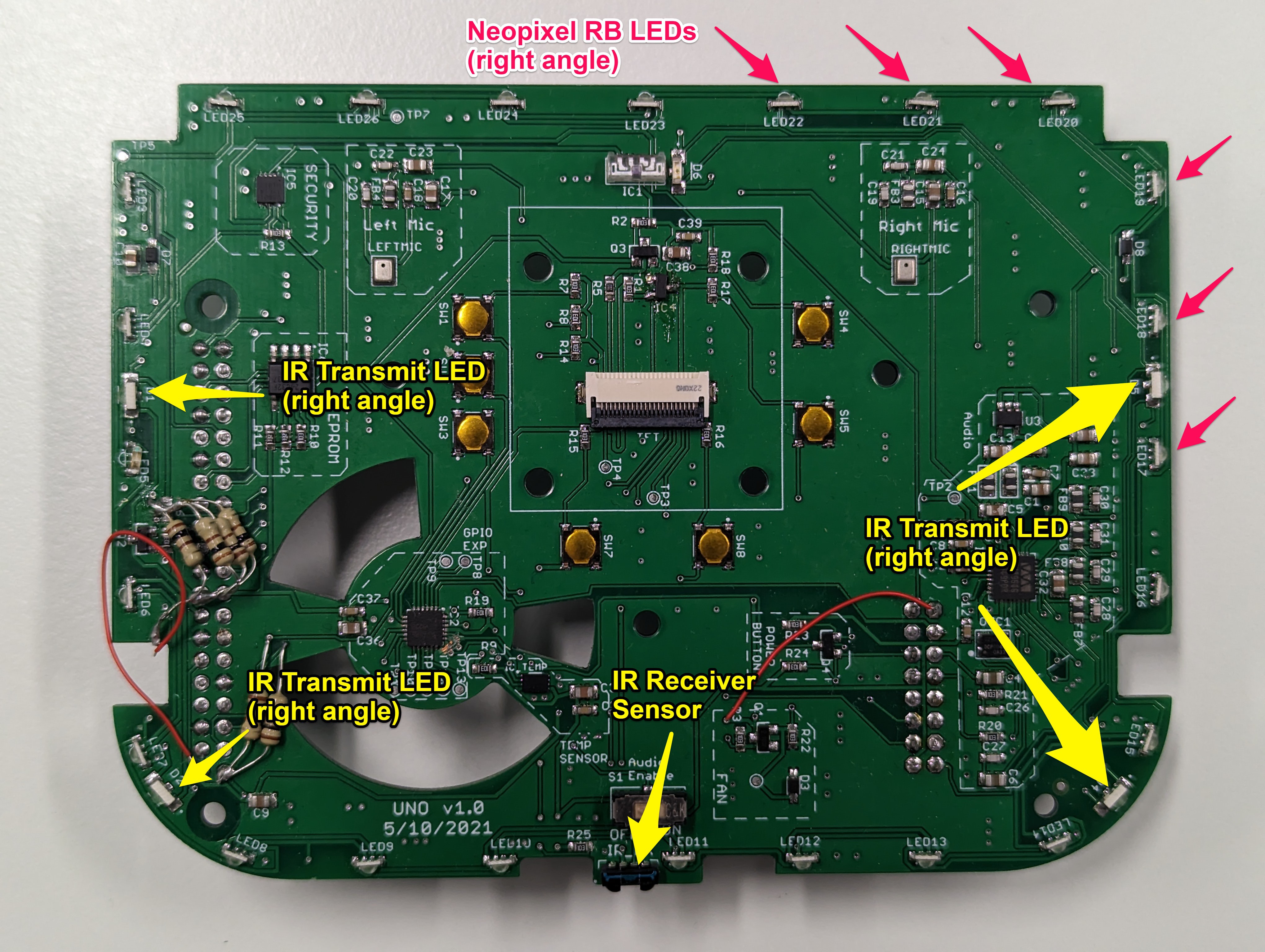
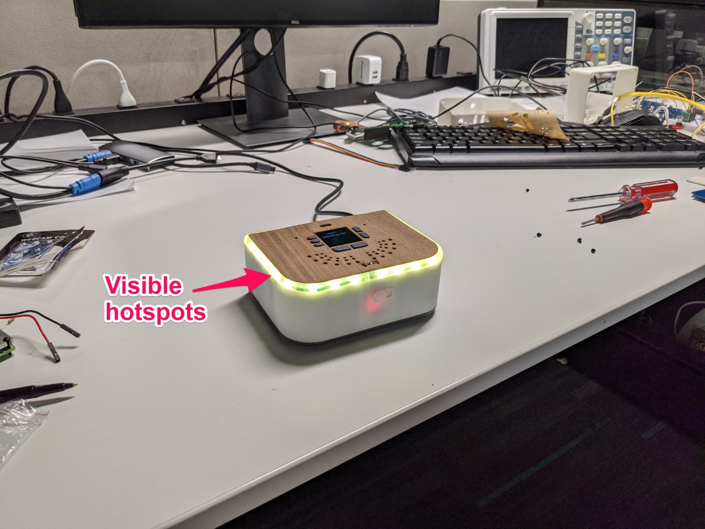
The picture below shows the first prototype. In the first prototype, I placed both the right angle addressable Neopixel RGB LEDs, InfraRed (IR) receiver sensor, and transmitter diodes on the edge of the PCB.
![]()
Since the RGB LEDs were too close to the LED light diffusing ring, this created visible hotspots and LED lights were not properly diffused.
![]()
To address this issue, I need to do several things (combination of following actions):
- Move back the RGB LEDs on the PCB for better diffusion
- Try top view LEDs instead of right angle so that light does not hit the ring directly
- Two-stage diffusion for RGB LED and single-stage diffusion for IR (more info on this later)
- Make the ring opaque (but not too opaque to block IR signal and decrease IR range)
The idea was to try to diffuse the RGB LED light as much as possible without increasing the opacity of the light ring material. In other words, increasing the opacity of the light ring material had to be the last resort since it would affect the IR light signal strength and lower IR range.
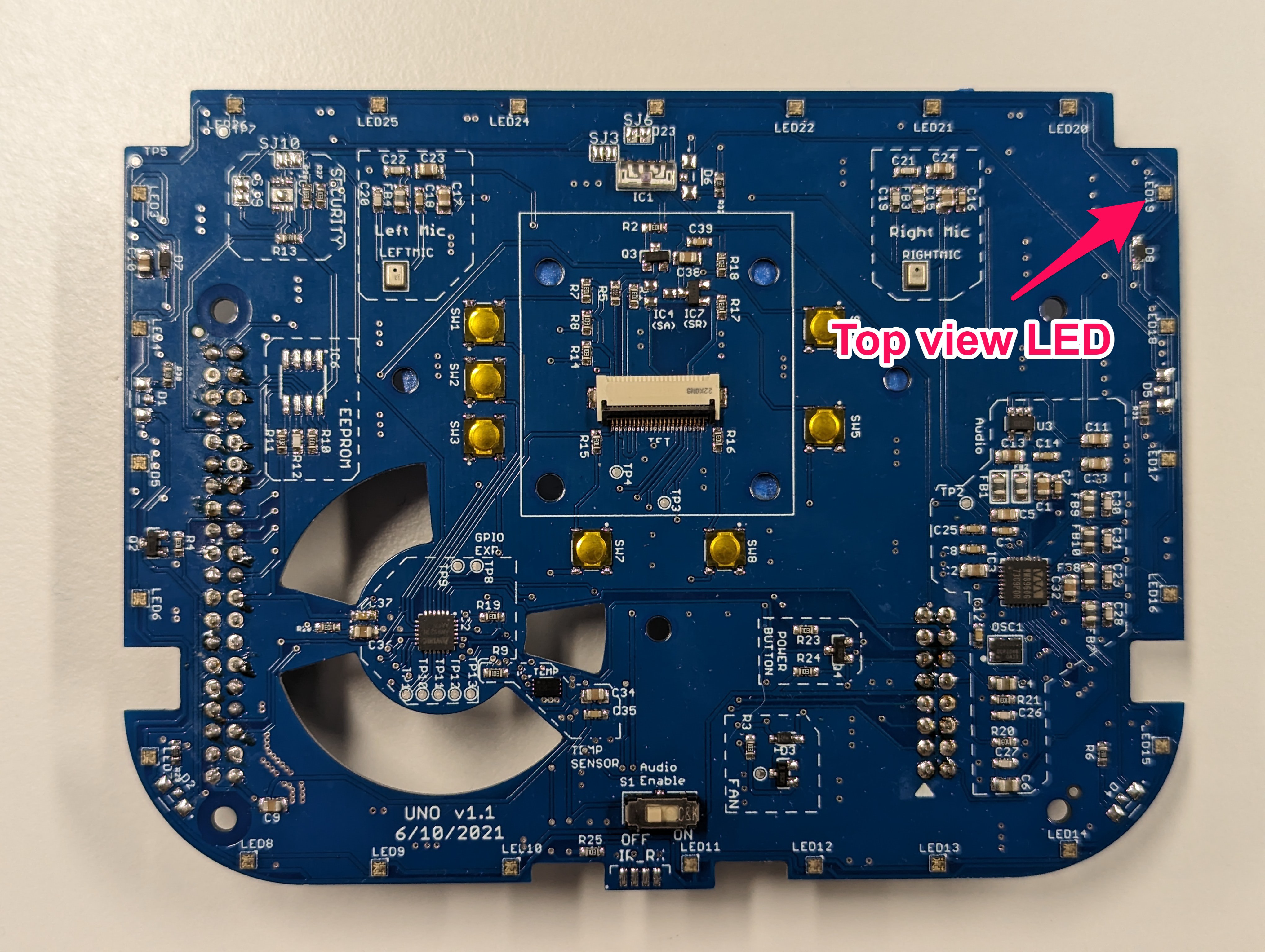
Since moving back LEDs required major change in PCB layout, I decided to try changing the LED type first to top view from side view first. This required only a change in LED footprint and I could spin out a revision very quickly. The picture below shows the PCB revision with this change:
![]()
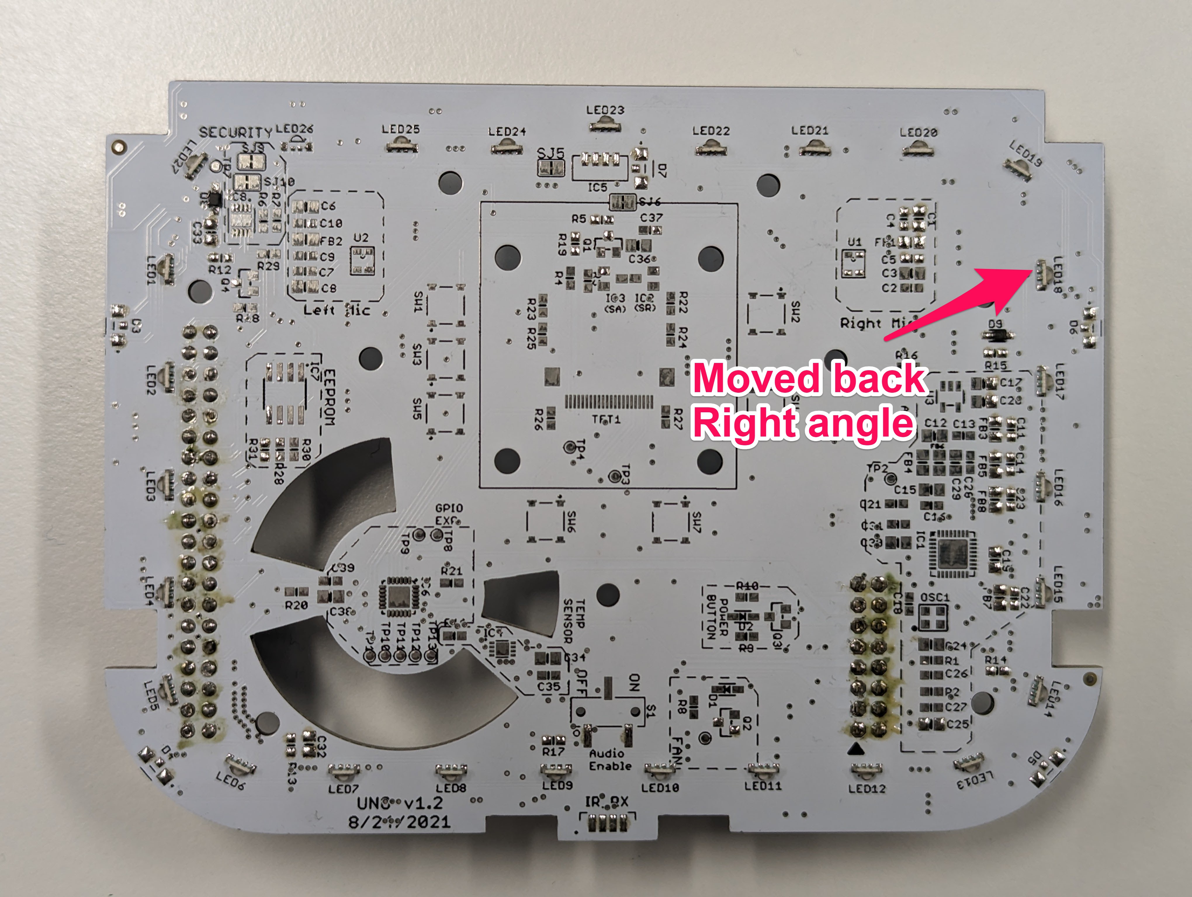
This change improved the hotspots by a small degree but it was not enough. So I decided to change the position of the RGB LEDs. The picture below shows the PCB revision with right angle LEDs moved around 6mm back from the previous position. Due to other design constraints, this was the maximum distance I could move back the LEDs on the PCB.
![]()
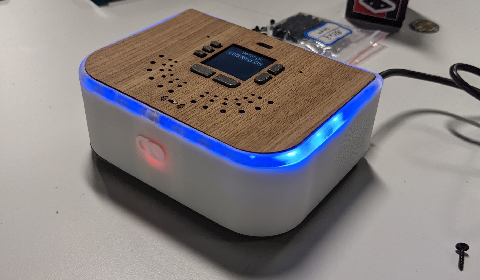
This change further improved the diffusion and the hotspots were less pronounced but I was not content with the end result especially if the ring was too transparent. So I decided to explore a two stage light diffusion.
![]()
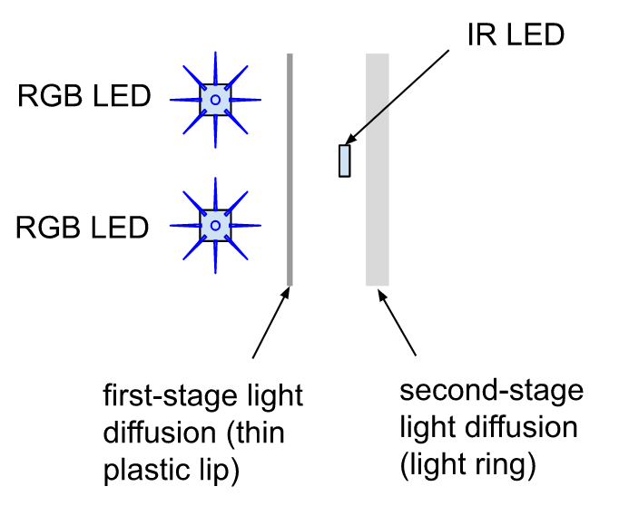
Two-stage light diffusion:
The picture below illustrates the idea for two-stage diffusion. To implement this idea, I added a thin lip (barrier) on the white plastic top cover right in front of the RGB LEDs to set up the first diffusion step. In this implementation, the IR LED light only gets diffused by the second stage diffuser (translucent ring) which does a very small amount of light diffusion. The main light diffusion is performed by the thin plastic wall in front of the RGB LEDs.
![]()
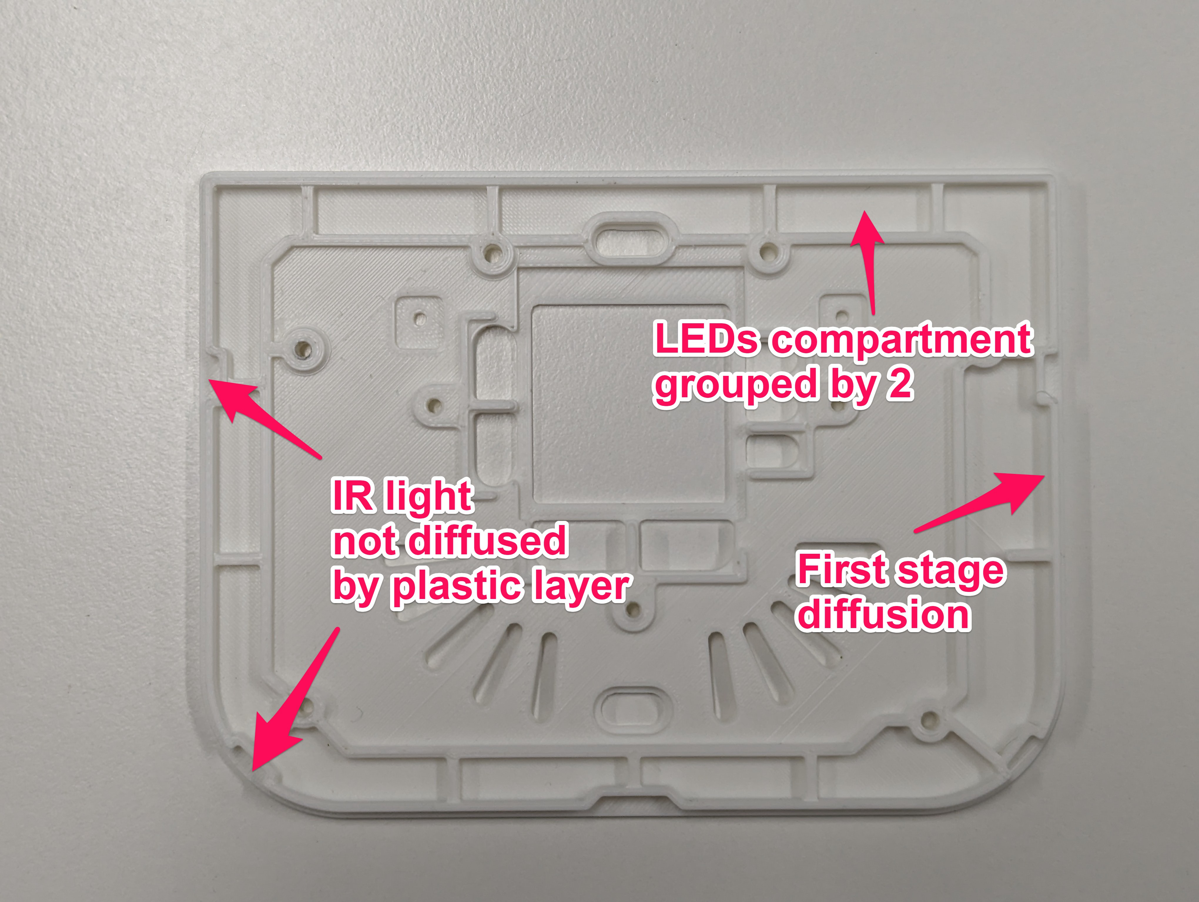
The picture below shows how this is implemented using the top white plastic cover:
![]()
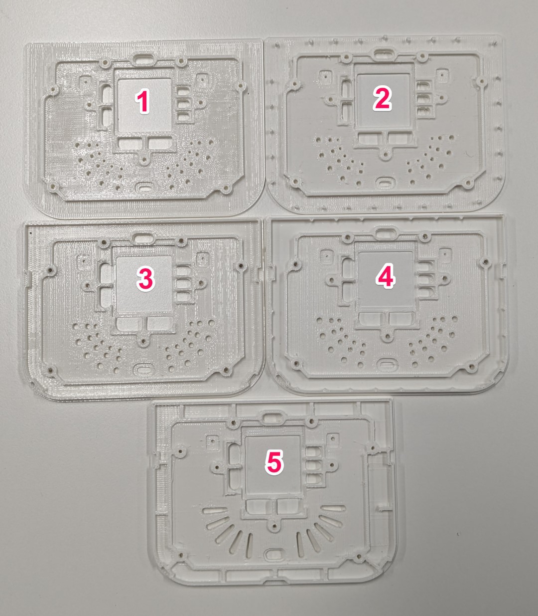
I experimented with several two-stage diffusion designs before settling on this design. I still believe there’s more room for improvement for better light diffusion here.
![]()
Light diffusing material
One of the challenging aspects of prototyping was experimenting with diffusion level for ring material. Initially, I 3D-printed the light ring with Formlabs 2 SLA printer using clear resin. However, this only resulted in a fixed degree of light diffusion which was not possible to control. Another problem was that no matter what light diffusion property I get with resin, I may not be able to reproduce that with injection molding plastic material. In other words, I needed to experiment with real material eventually and the resin could only give me some indication of desired level of light diffusion.
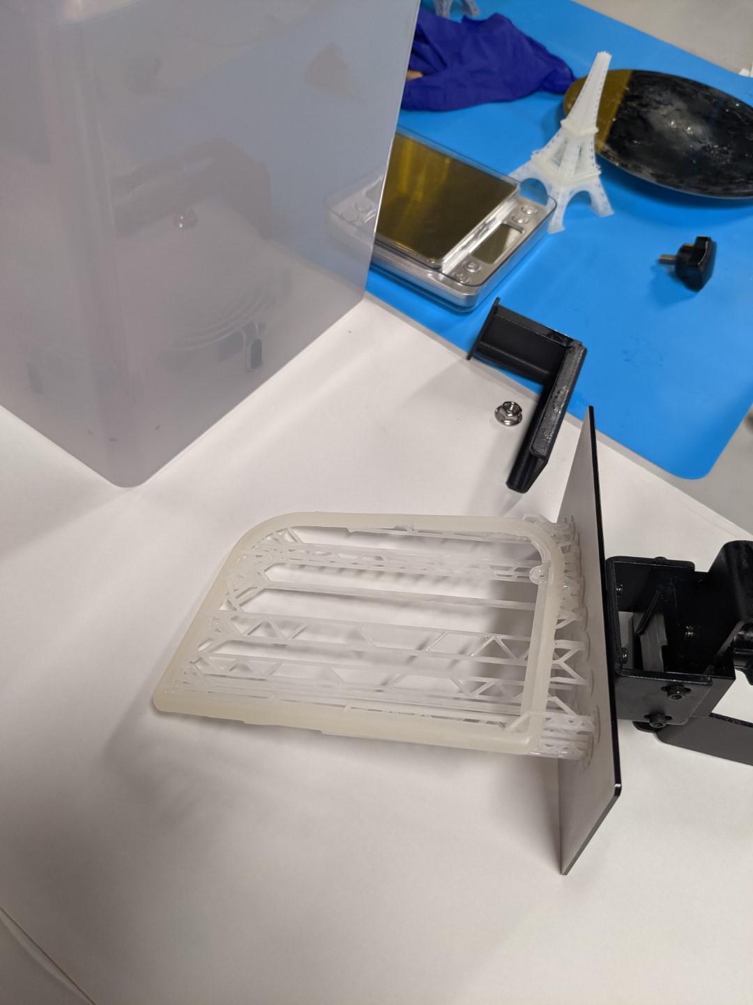
The first technique I used to control the diffusion level / opacity was to try to mix clear and white resins with different rations. Formlabs 2 3D printer posed some challenges to print with custom resin material since (a) Formlabs is tuned to work best with its own resin system (b) I had to use a new tank for this experimentation and It was possible to damage the tank. Due to such limitations, high-cost, and overhead of such experimentation, I decided to buy a cheap Creality SLA printer. This way, even if I messed up the FEP or the tank, I could replace the FEP. The cost of resin was lower and I could only mix the amount I needed to print and not much more. Lastly, I had more control over printing parameters.
![]()
I tried different mixing ratios (such 20:1 and 10:1) to get various degrees of opacity. It turned out that the 10:1 ratio did a good job of diffusing the LED light while passing through IR with minimal loss.
Injection molding
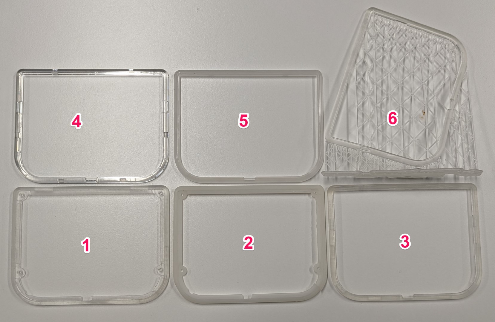
After getting some more confidence about the design, I decided to make my first injection molding tool for Ubo. This was a bit scary at first due to the high cost of injection molding, but it was the only way I could measure exact characteristics. It is very common to use Polycarbonate (PC) with polished surface finish for lighting applications. I decided to make the ring with two types of PC (1) clear (2) 95% translucent. Rings number 4 and 5 in the picture below show clear and translucent rings respectively.
Now with the real material in hand, I needed to measure the loss in IR signal with each type of PC material used.
![]()
IR testing range
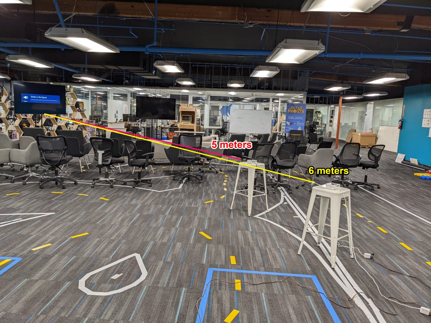
The image below shows the setup for measuring the IR transmit range. In this setup, I sent on/off commands to the TV and kept increasing the device distance until the TV stopped receiving the command. I repeated this experiment under three set-ups (a) no light ring assembled, (b) clear PC light ring, and (c) translucent PC ring assembled.
![]()
The IR range measured for cases (a) and (b) were identical as expected at 6 meters. The distance measured under setup (c) only showed 5-10% reduction to around 5.5~5.7 meters. I was overall content with the end result.
If you have any questions, please do post it on the comment section below and I will reply asap. There might be some more information that I might have left out in the project log but I will update the log to include them.
-
Hardware Hacking w/Boomboxes
04/24/2023 at 21:06 • 0 commentsOne of my frequent questions to self these days is, can we put an Ubo in it?
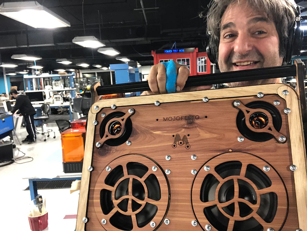
Among the great things that come from working at a co-working space dedicated to hardware start-ups, are some of the great people and projects that just happen to be your neighbors. Noel here created makeboomboxes.com and we've been kicking around the idea of "Ubo-izing" it. So an exploration to go from aluminum to wood is underway.
![]()
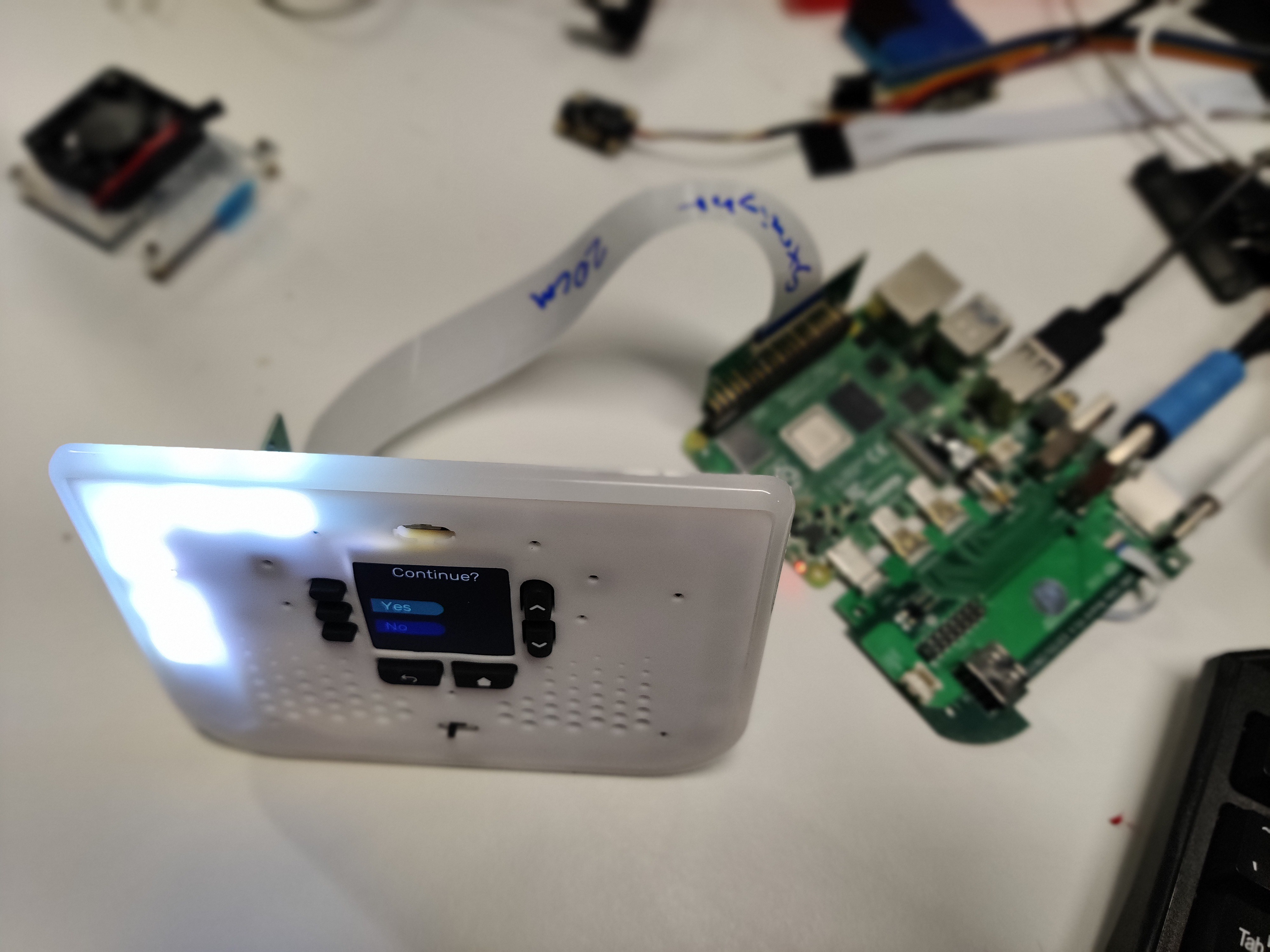
I look forward to adding another progress update soon, and in the mean time I wanted to pass along something fresh off the desk. We are playing with making the board more flexible, by extending the 40-pin GPIO header with a flex cable adapter starting with a Adafruit FPC adapter and 20cm cable. Here's the first proof of concept test to let us put the display and buttons on top of the boombox, and then mount the pi out of the way elsewhere on the inside.
![]() I think this looks promising enough to say "Yes", I will continue. This will still require making a custom cable to convert the 2x8 header coming back off the top board to a 3.5mm stereo audio connection and a GPIO to re-connect the power going to the fan.
I think this looks promising enough to say "Yes", I will continue. This will still require making a custom cable to convert the 2x8 header coming back off the top board to a 3.5mm stereo audio connection and a GPIO to re-connect the power going to the fan. -
Hello Hackaday Prize 2023!
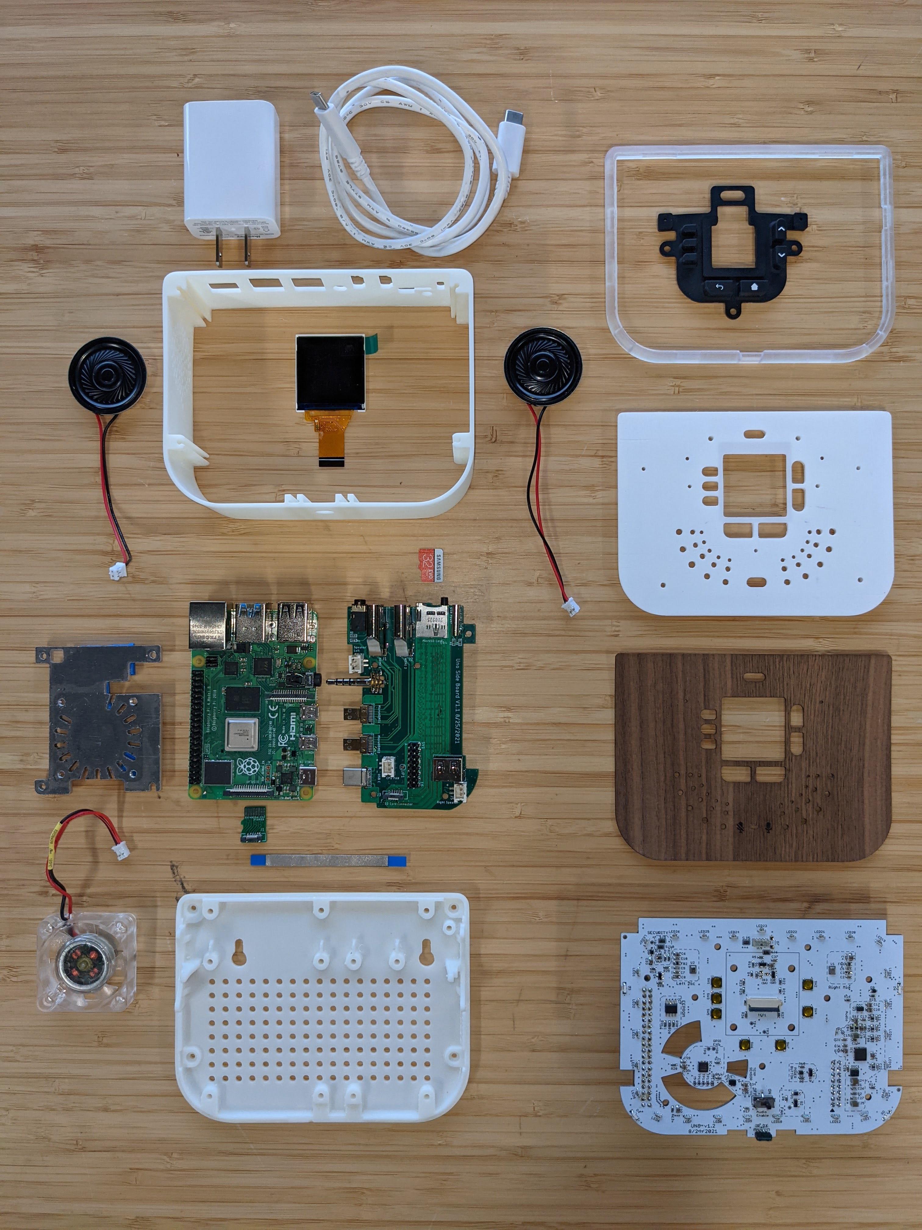
04/24/2023 at 20:30 • 0 commentsHere are the core components of the hardware inside Ubo. The enclosure wraps around a Raspberry Pi 4 which plugs into the Side Board re-routing the HDMI, power, audio and SD card so that they are all available to access on the back of the enclosure along with the Ethernet and USB ports.
* Note this is an image of several early pre-production prototype pieces, such as 3D printed body, and base. The current body is an aluminum extrusion, and the base is injection-molded.
![]()
The top PCB, shown on the lower right, supports a 1.54" 240x240 resolution color display along with 27 RGB LEDs (SK6812), and two microphones able to record 48 KHz stereo audio. The customized heatsink allows for running without active cooling for most tasks. With the fan the CPU can be overclocked to 2.1 GHz without throttling. Integrated sensors include +/- 1C accuracy temperature sensor (PCT2075) and 0-120 Kilolux ambient light sensor (VEML7700).
The full schematic with all of the hardware component details are available at https://github.com/ubopod/ubo-pcb
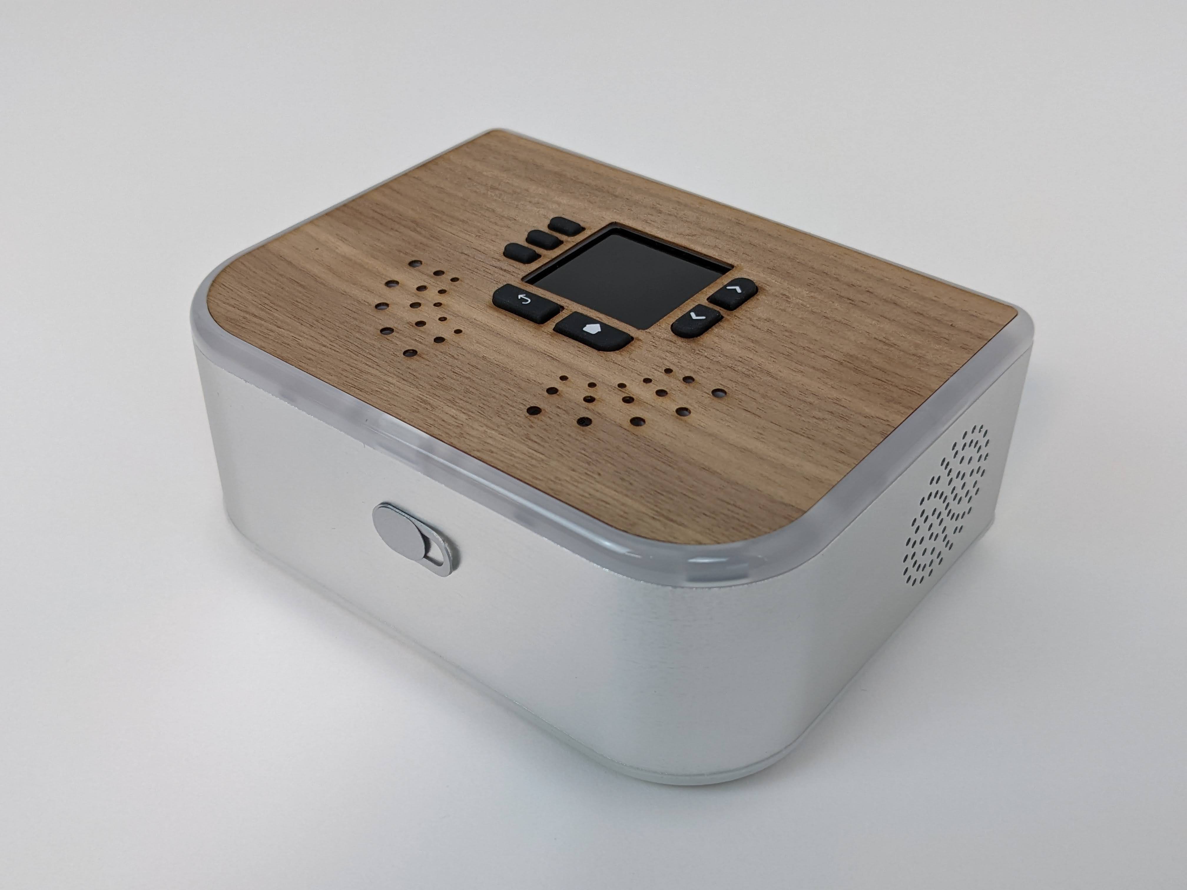
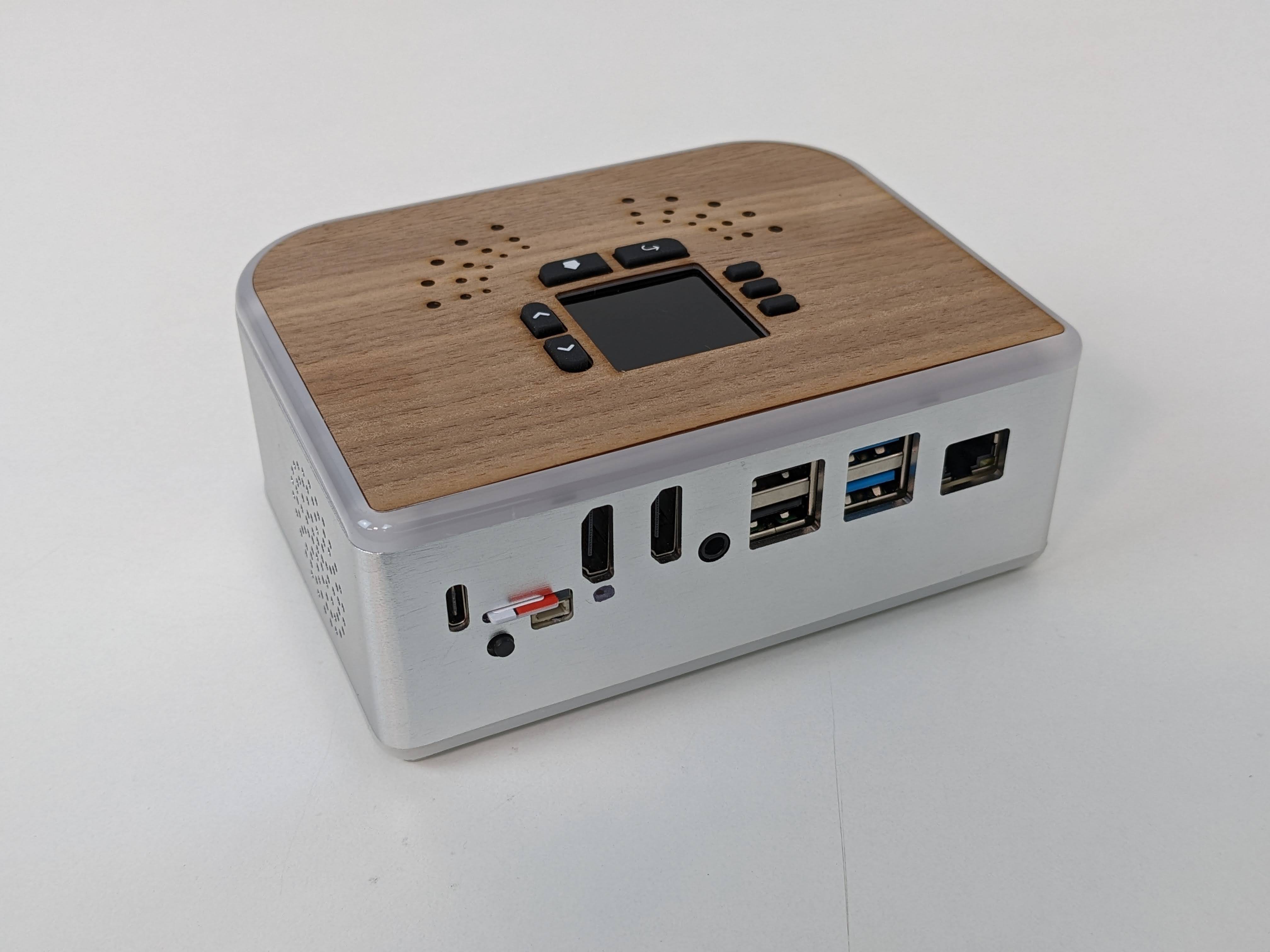
And here is the finished result, freshly prepared for our first Hackathon...
![]()
![]()
While we really enjoy digging in to the hardware, and look forward to sharing a lot of insights and learning along the way, sometimes you just want to get to the code! During our hackathon we started to test and get feedback on the SDK that we are developing as well. Like the hardware, our software development is open source and will continue to be updated at https://github.com/ubopod/ubo-sdk
We are quite proud of the development that has gone in to the customized PCB boards and enclosure. However, we don't want this to be your only option. While current code base is highly focused on specific hardware, it is intended to be as customizable as possible. In other words you can just bring your own Raspberry Pi and get started with that. A lot of the libraries play well with Circuitpython and can be used with any number of sensors and input/output devices to create a version of your own.
We look forward to the journey and input from the Hackaday community and continue to hone our overall direction, also fueled by the challenge of Re-engineering Education.
Ubo Pod: Build Apps with Rich UX on Raspberry Pi
An open source dev kit to build Raspberry Pi app with rich UI/UX with an easy to use SDK

 I think this looks promising enough to say "Yes", I will continue. This will still require making a custom cable to convert the 2x8 header coming back off the top board to a 3.5mm stereo audio connection and a GPIO to re-connect the power going to the fan.