 Neil Lambeth
-
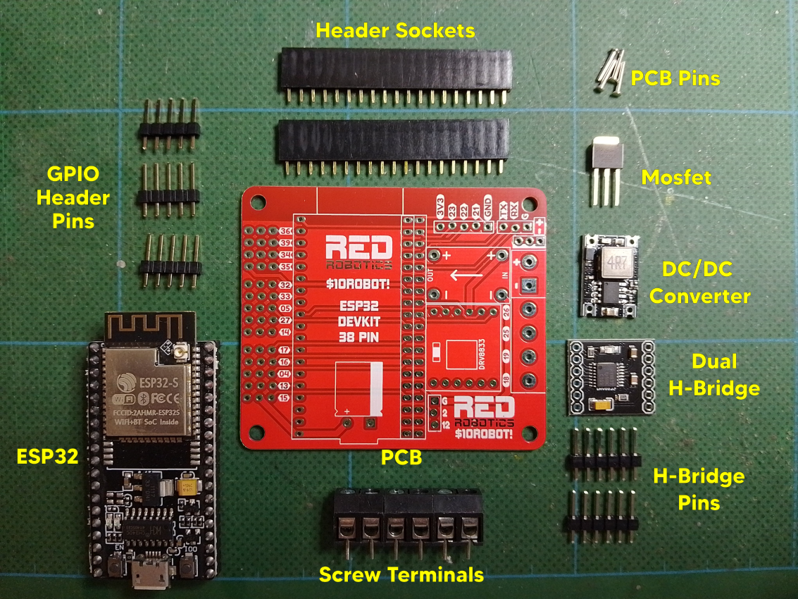
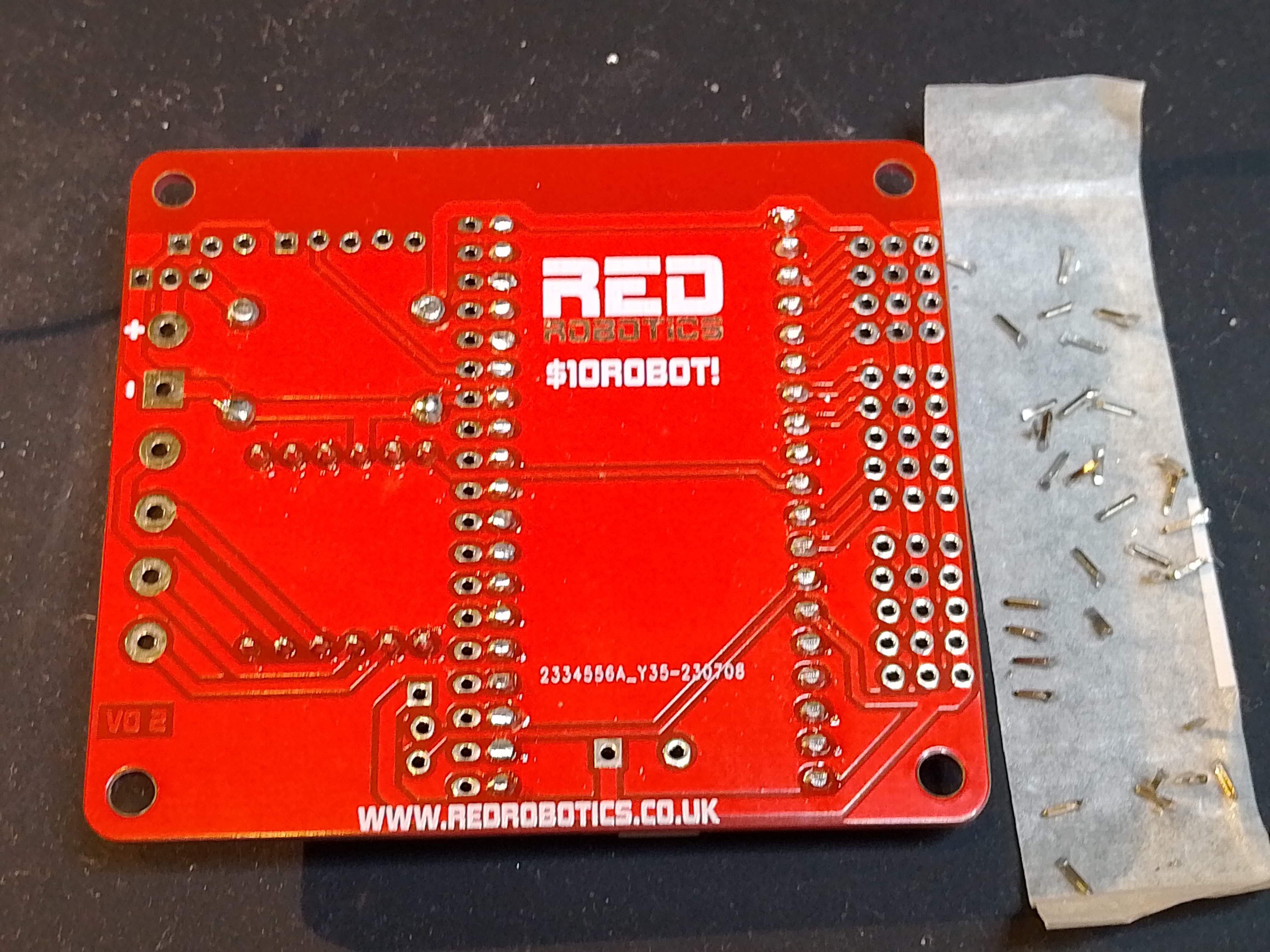
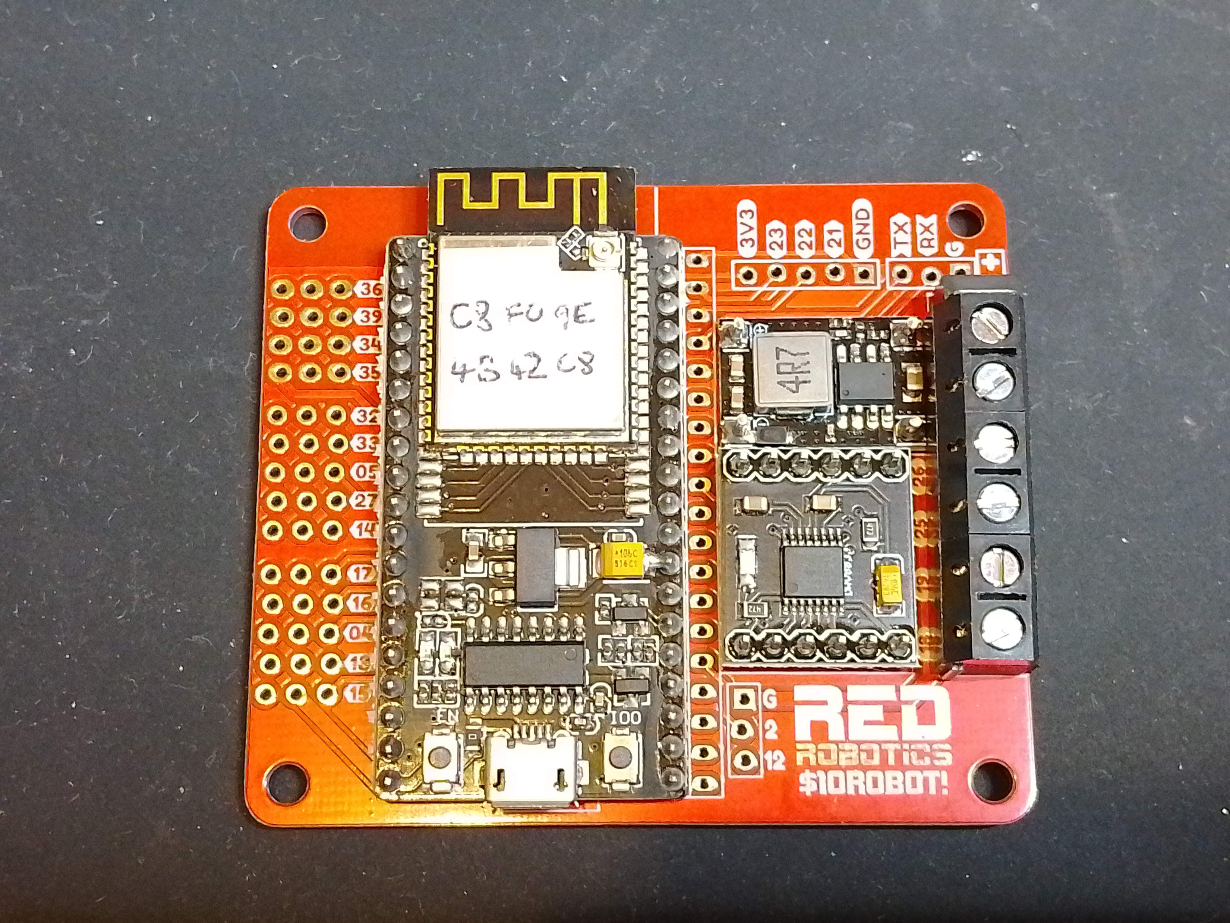
1Gather all of the components.
Some of them are optional, you don't necessarily need the header sockets as the ESP32 module can be soldered directly to the board for a more low profile look. You also don't need the GPIO pin headers on the left hand side unless you want to control servos or read sensors etc.
![]()
-
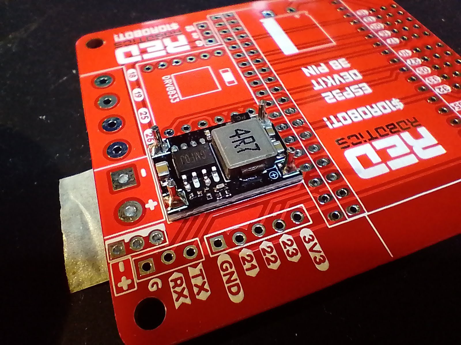
2DC/DC Converter
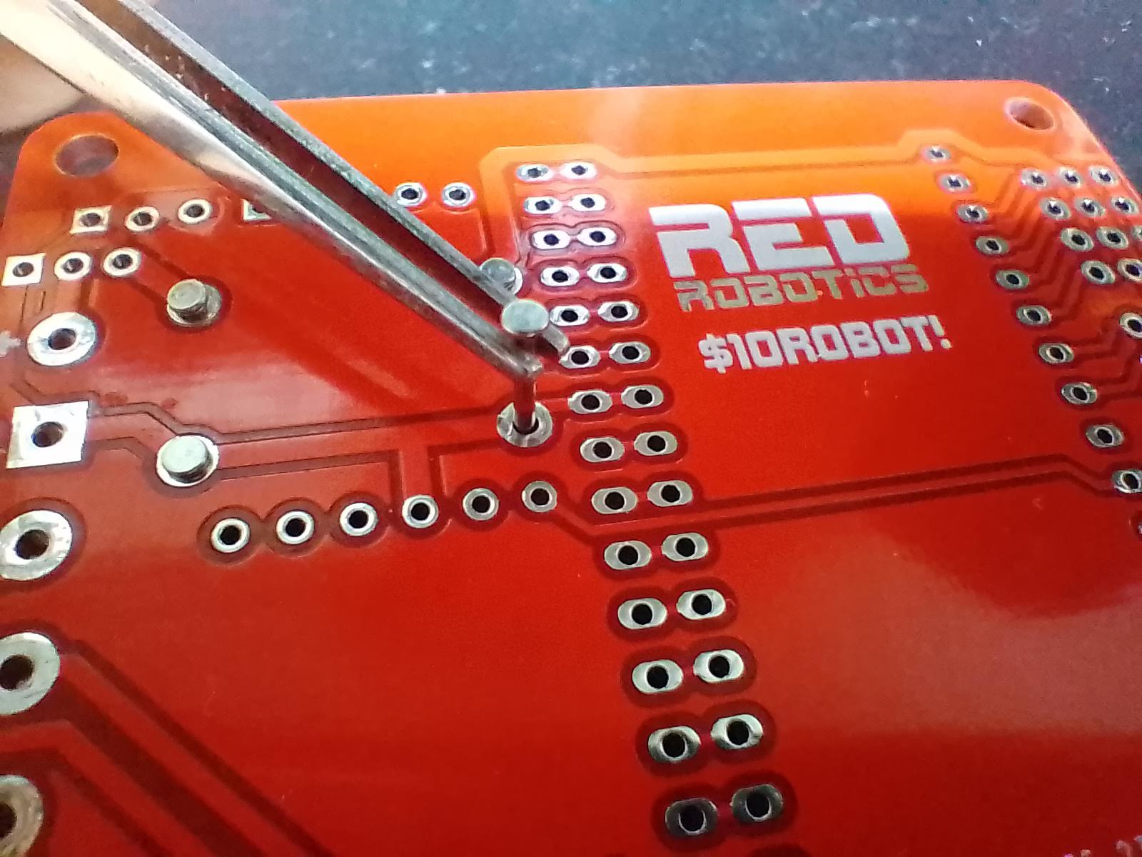
Flip the board over and insert the PCB pins for the DC/DC Converter.
![]()
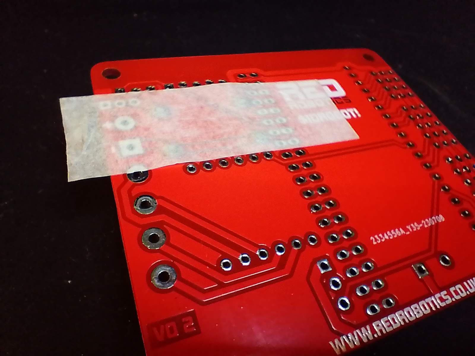
Use a bit of masking tape to hold them in place.
![]()
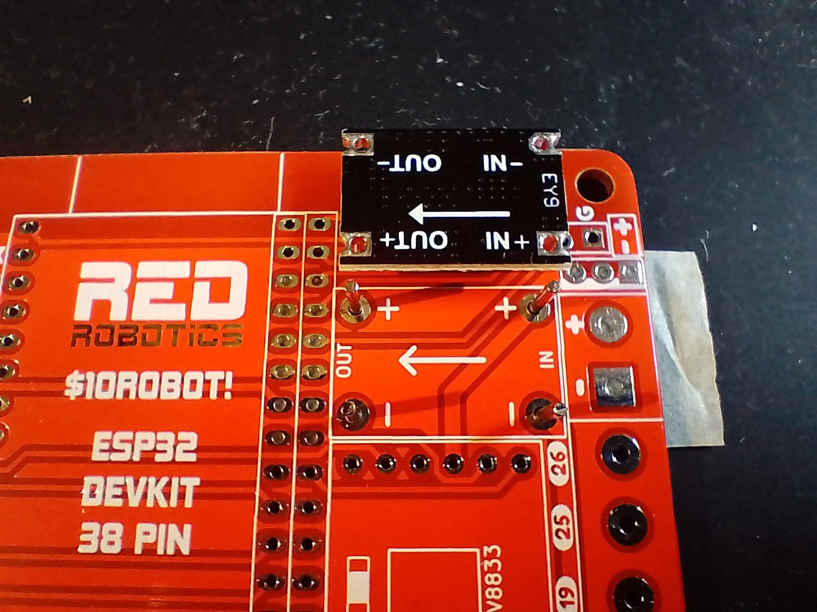
Look at the underside of the DC/DC converter and make sure the arrows are pointing in the same direction.
![]()
Flip the DC/DC Converter the right way up, place it over the PCB pins, then solder the pins on the top side first. When all 4 pins are done, flip the whole PCB over, remove the masking tape and solder the 4 pins on the underside.
![]()
-
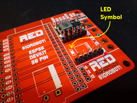
3Dual H-Bridge
Insert the 2 6-way header pins for the Dual H-Bridge.
![]()
Flip the board over and solder the pins on the underside. Make a note of the position of the symbol of the LED as you'll use this to orientate the Dual H-Bridge.
Flip the board back over, insert the Dual H-Bridge then solder the pins.
![]()
-
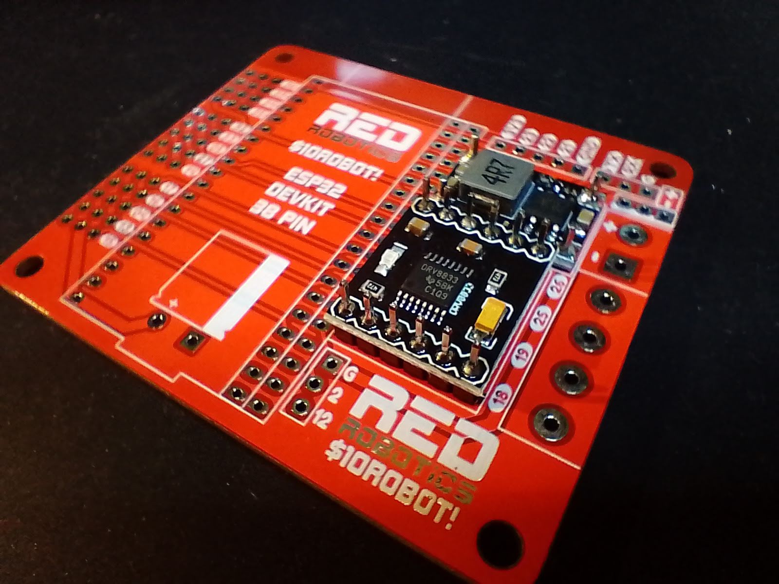
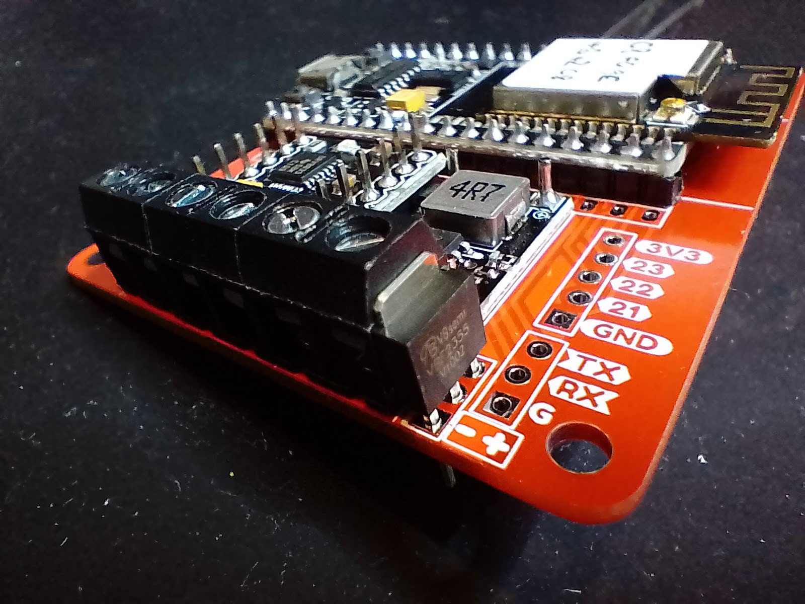
4ESP32 DevKit
Insert the ESP32 DevKit. For this board I'm using the 38pin narrow version. If you are going to use the header sockets, attach them to the ESP32 DevKit first, so that they line up properly.
Flip the board over and solder all the pins.
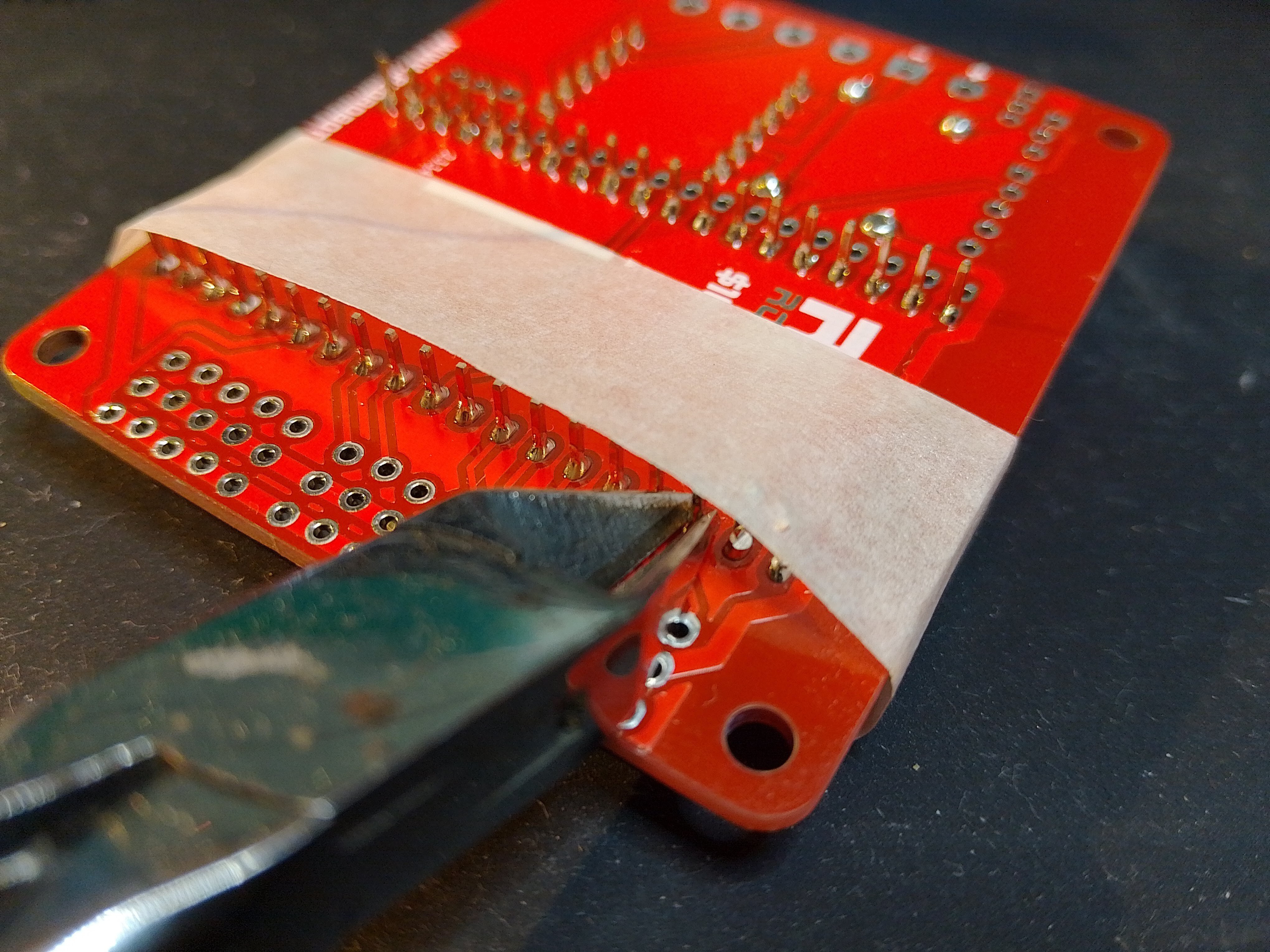
If you have soldered the ESP32 directly to the board, you will want to cut off the pins that are left sticking out of the underside of the board.
Wear safety goggles and cover the pins with a some masking tape as they have a tendency to go flying off across the room when you cut them!
![]()
![]()
-
5Screw Terminal
Insert the Screw Terminal and solder from the underside, easy!
![]()
-
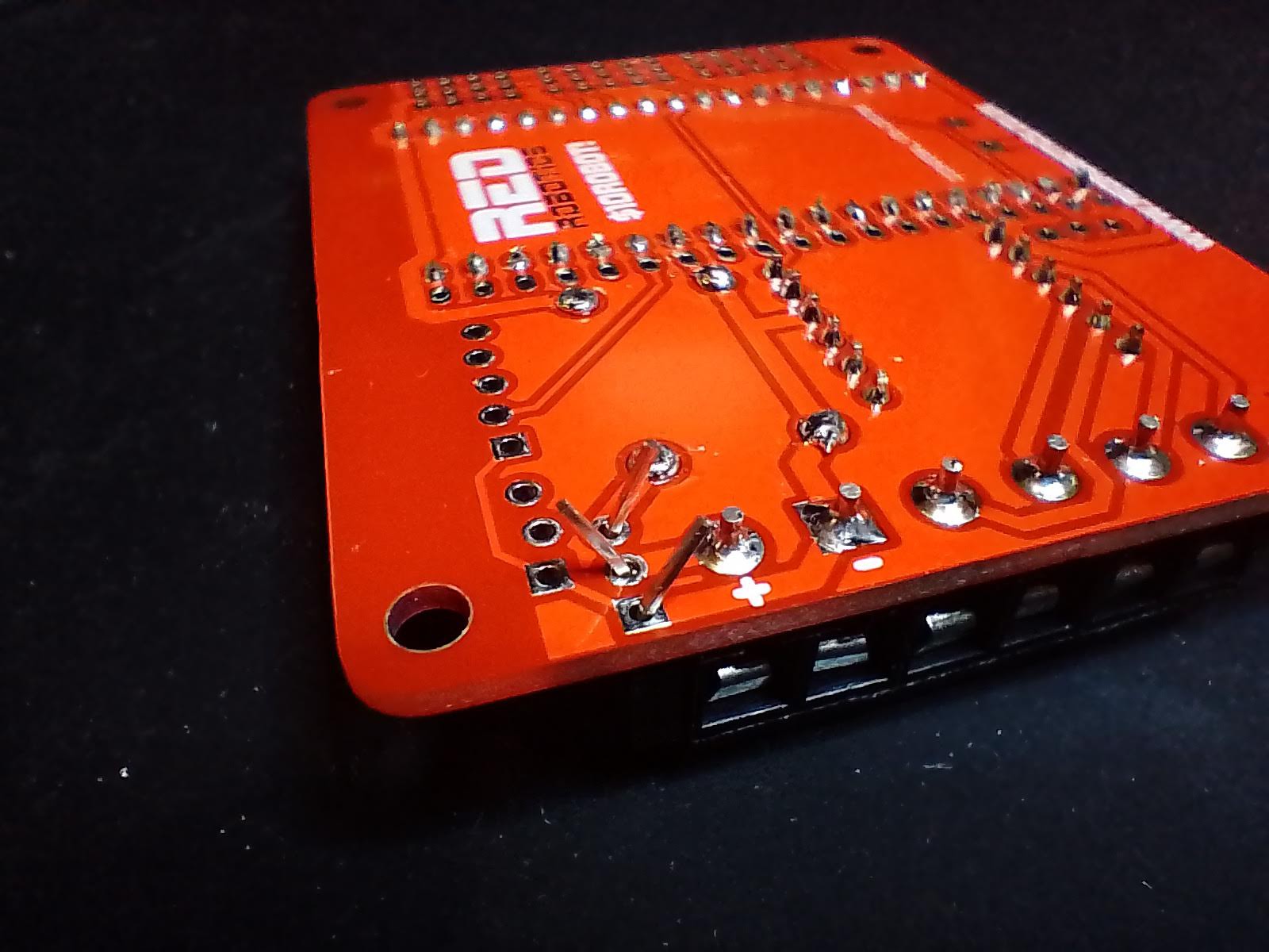
6Mosfet
The Mosfet adds reverse polarity protection. Insert it with the tab next to the Screw Terminal.
![]()
You can bend the legs slightly, so that it doesn't fall out when you flip it over.
![]()
-
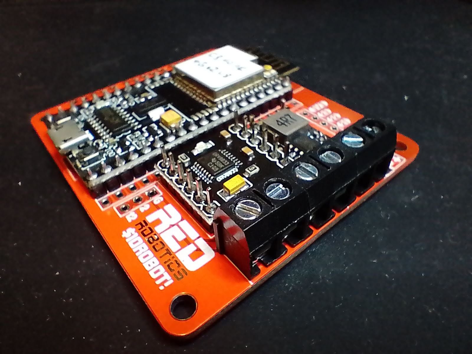
7Done!
![]()
That's all you need to do to get the basic robot working. You can always solder in more GPIO header pins as you need them.
-
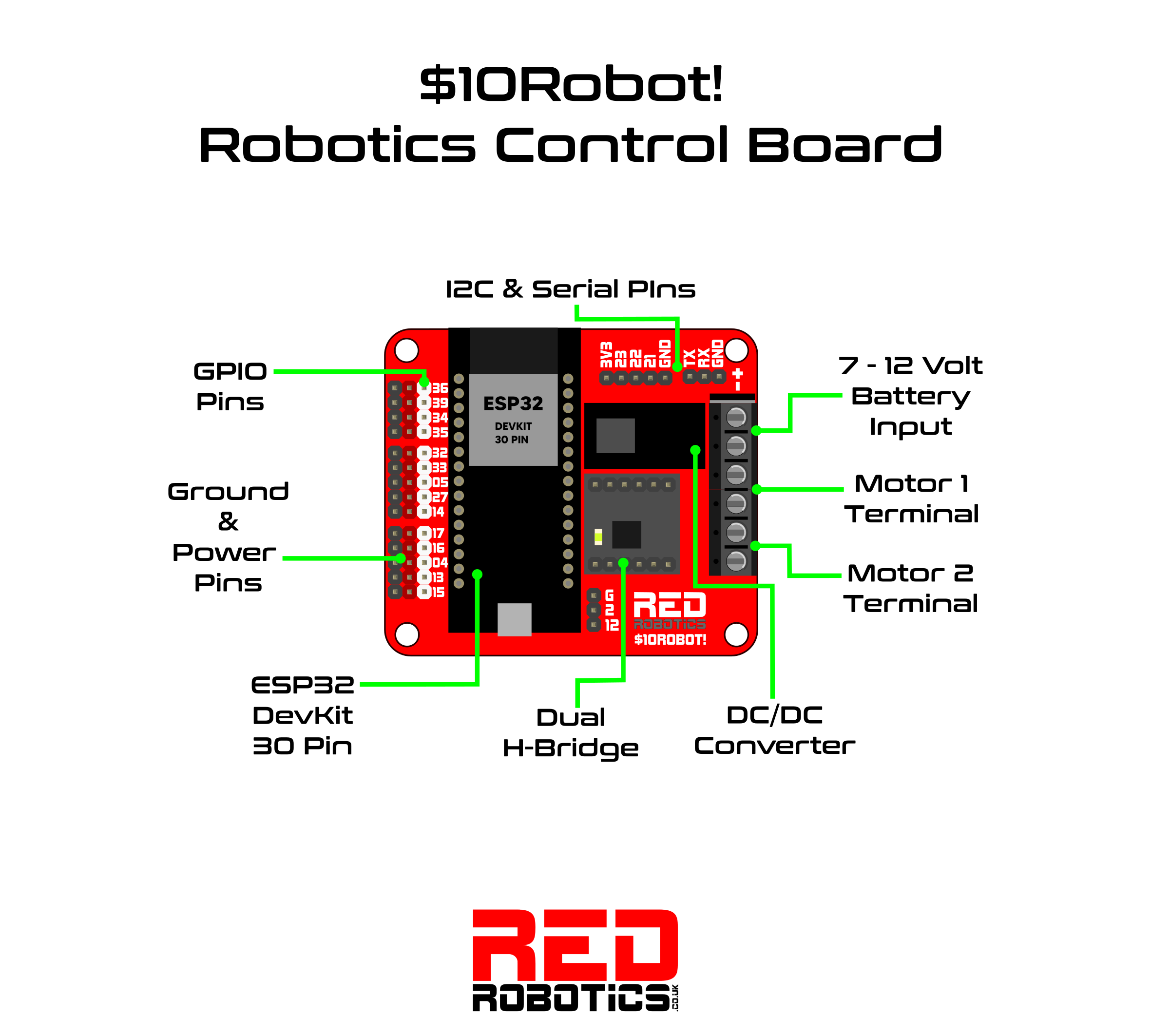
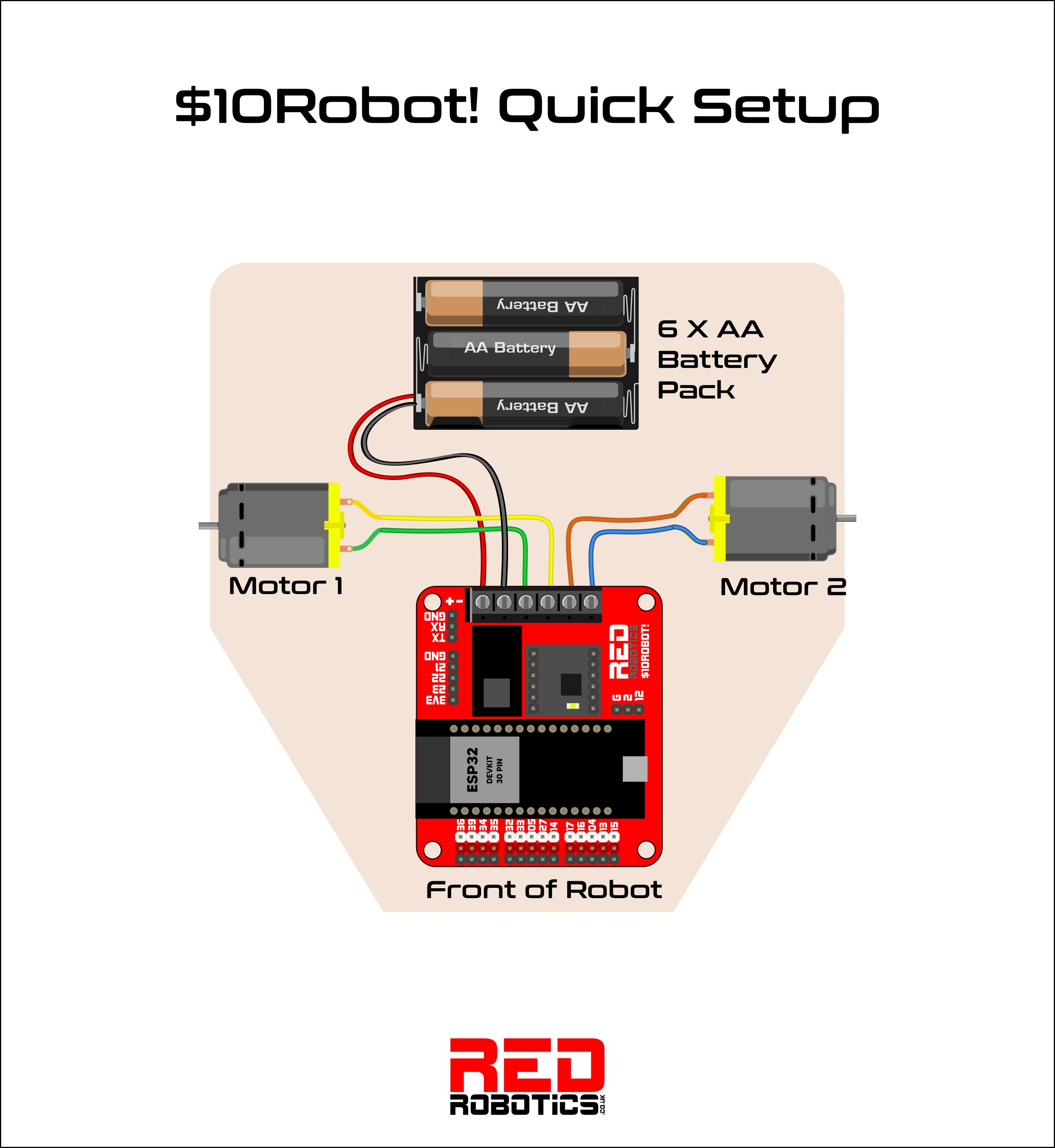
8Wiring Diagram
![]()
![]()
-
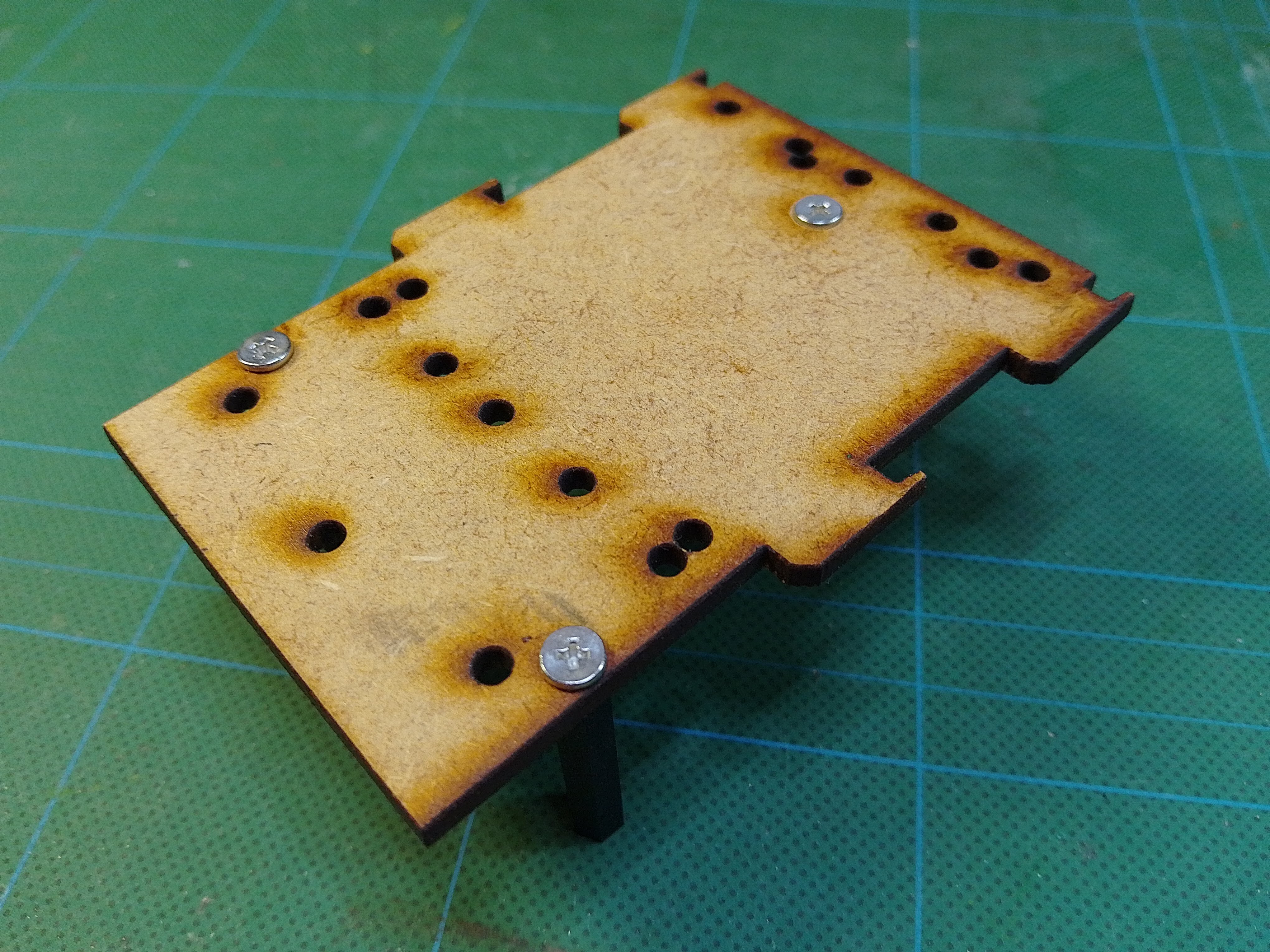
9Chassis Assembly
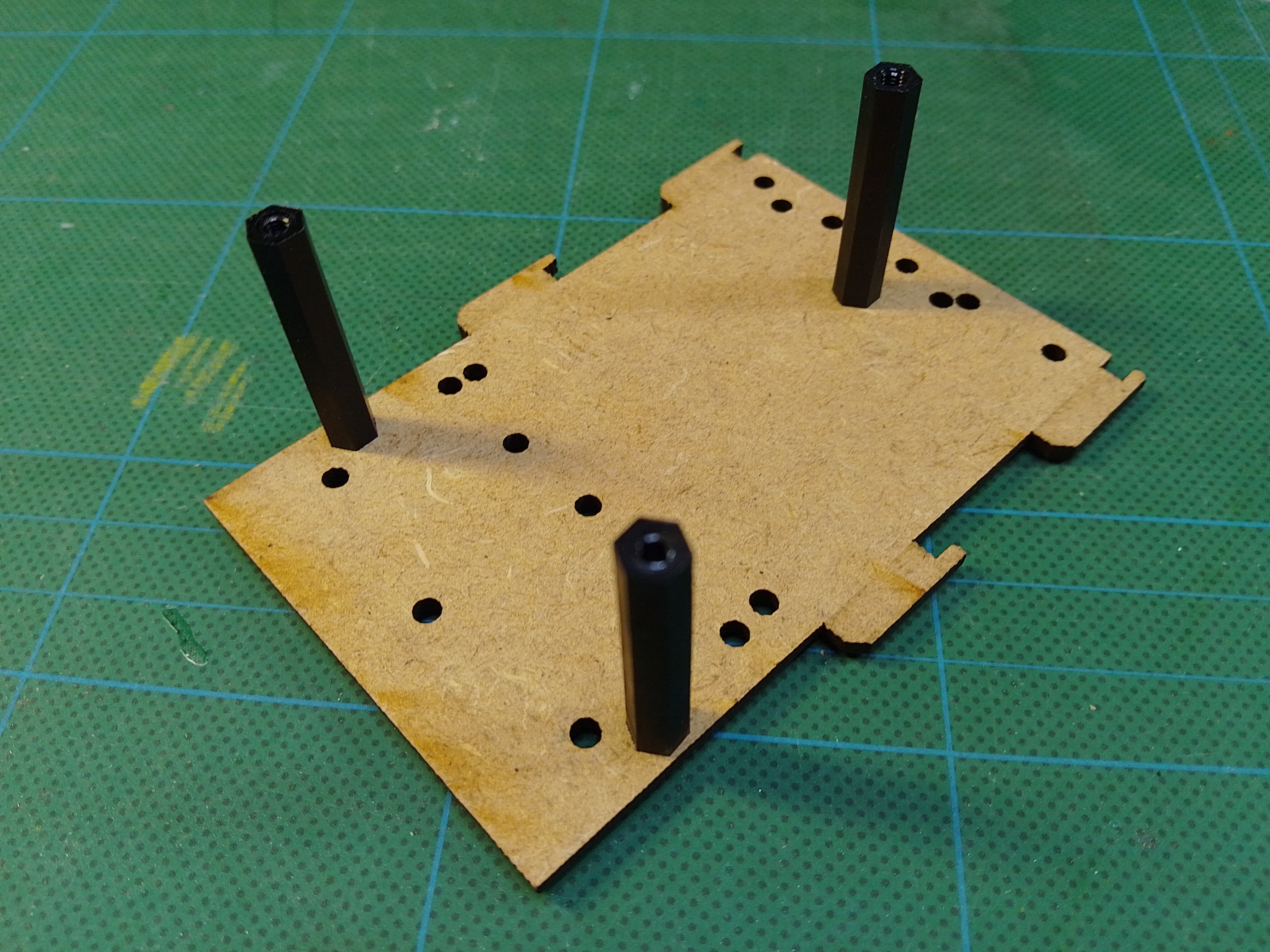
Once you have laser cut and 3D printed all the parts, you can start assembly of the chassis.
Start with the middle section and screw in the 3 32mm hex spacers. Copy the pictures below, but there's a few different options for where to screw in the spacers if you want to use different batteries.
![]()
![]()
-
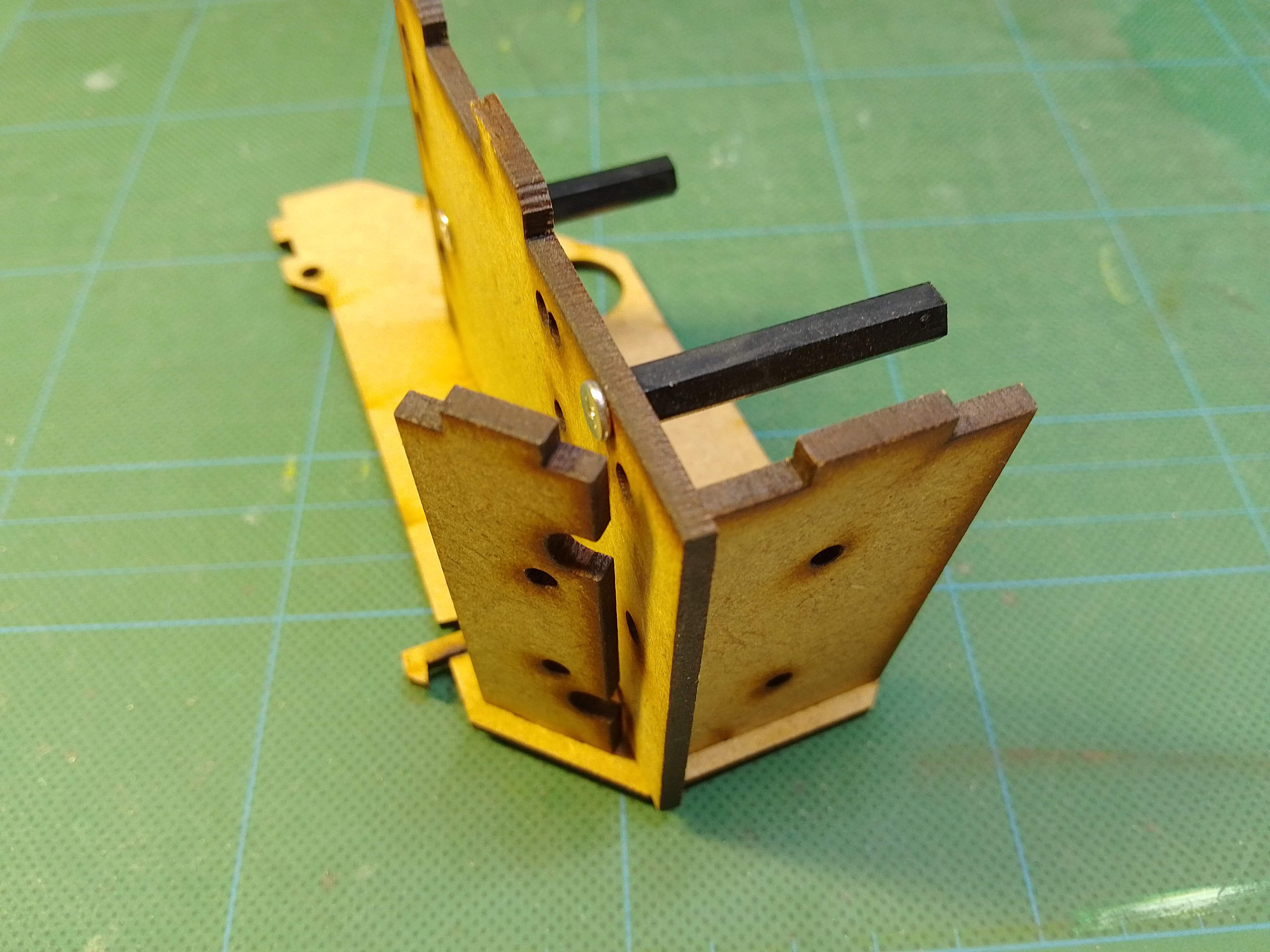
10Step 10
Now attach one side and the two front pieces. They will be a bit wobbly until we put the screws in.
![]()
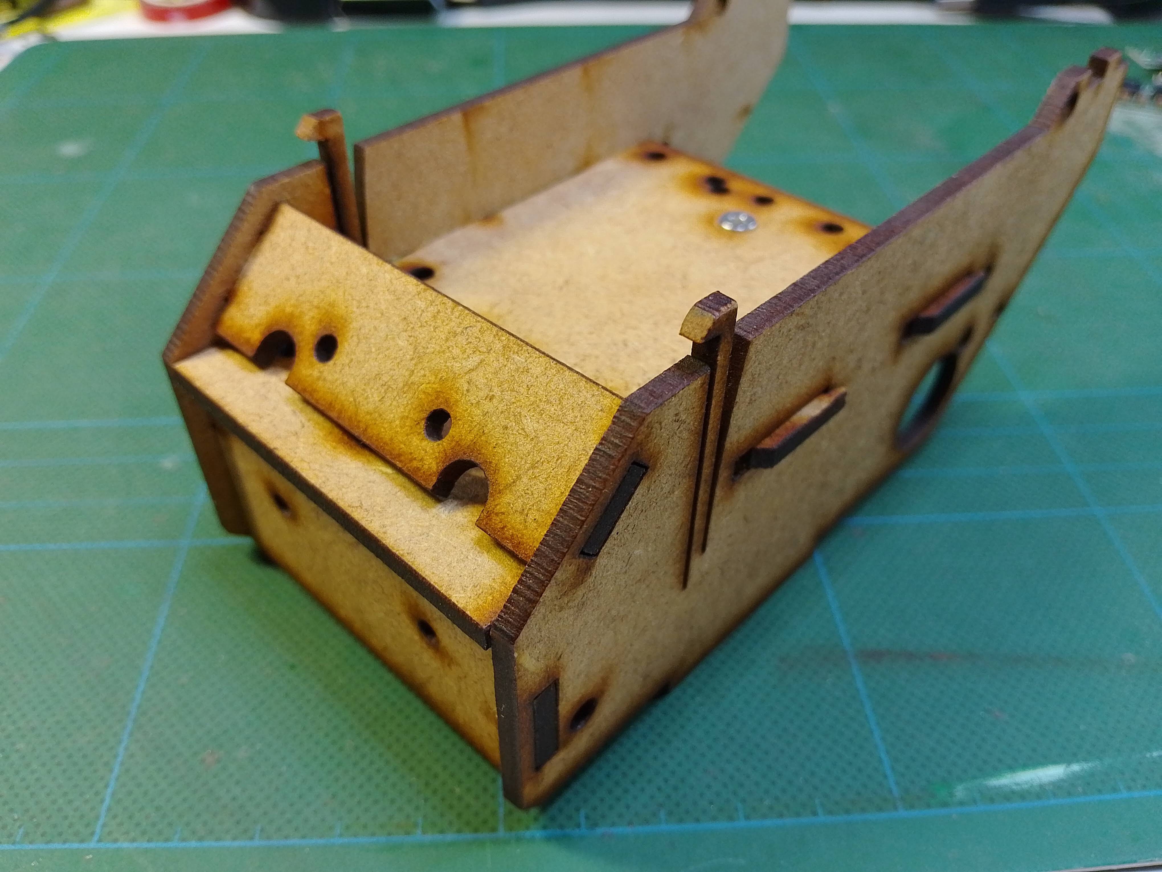
Now attach the other side, making sure to line up the tabs with the slots. Then push the middle section back a few millimetres to help hold things in place.
![]()
$10 Robot!
A super cheap educational robotics platform. Everything you need to build and program a simple robot.
Discussions
Become a Hackaday.io Member
Create an account to leave a comment. Already have an account? Log In.
No problem, I'll add it to the Files section to make it easier to find as well.
Are you sure? yes | no
I am sorry. The firmware is in the LOGS section. I missed it.
Are you sure? yes | no
Would you supply the firmware for the ESP32? It would be hard for the student to start from scratch to program the robot.
Are you sure? yes | no