Neil Lambeth
-
Cutting Costs
09/21/2023 at 20:24 • 0 commentsThe M5 Stamp was a great board to get this project going, but it's a little too expensive, so I started looking at other ESP32 boards.
I already had a few in my parts bin, so I started playing around to see how they would fit in with my original board design. I started with the basic ESP32 surface mount module, as this was very similar in size to the M5 Stamp so It was pretty easy to modify the design.
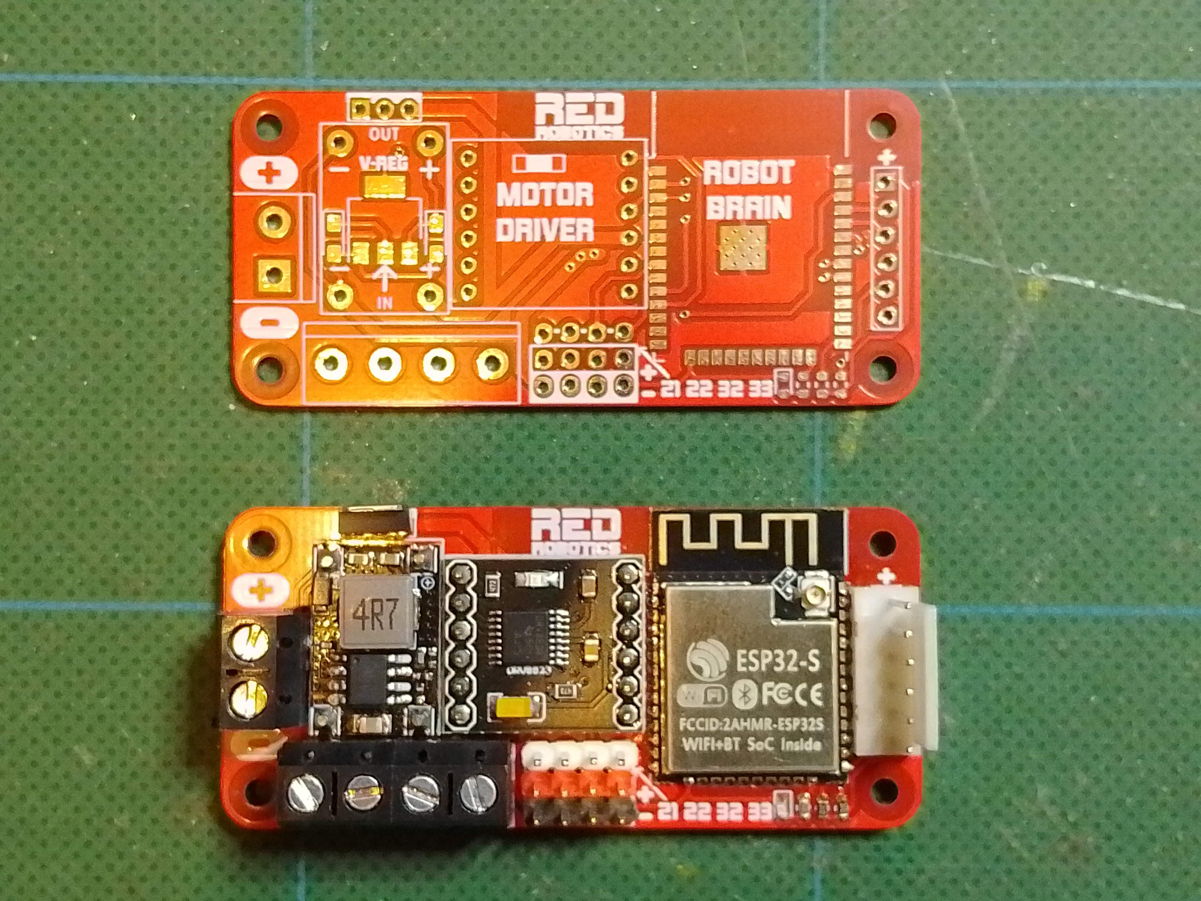
Here's the result:
![]()
Pretty happy with this as it has met most of my original requirements, It keeps the Pi Zero format and the best thing about them is that they only cost $1.60. The down side is that they don't have a USB port so an external programmer will need to be used, this could work in the Robotics Club, as students could share, but it's not so great if that want to take them home. The cost of the programmer would negate any cost saved from using the cheaper module.
I also had some of the ESP32 DevKits, these are useful little development boards, as they have the ESP32 module plus the USB connector and associated circuitry. This makes them very easy to use, the downside is that that are quite a bit bigger and so they won't fit inside the footprint of a Pi Zero. What's also a bit confusing, is that there seem to be a few different styles of these boards with different pinouts.
-
Chassis Design
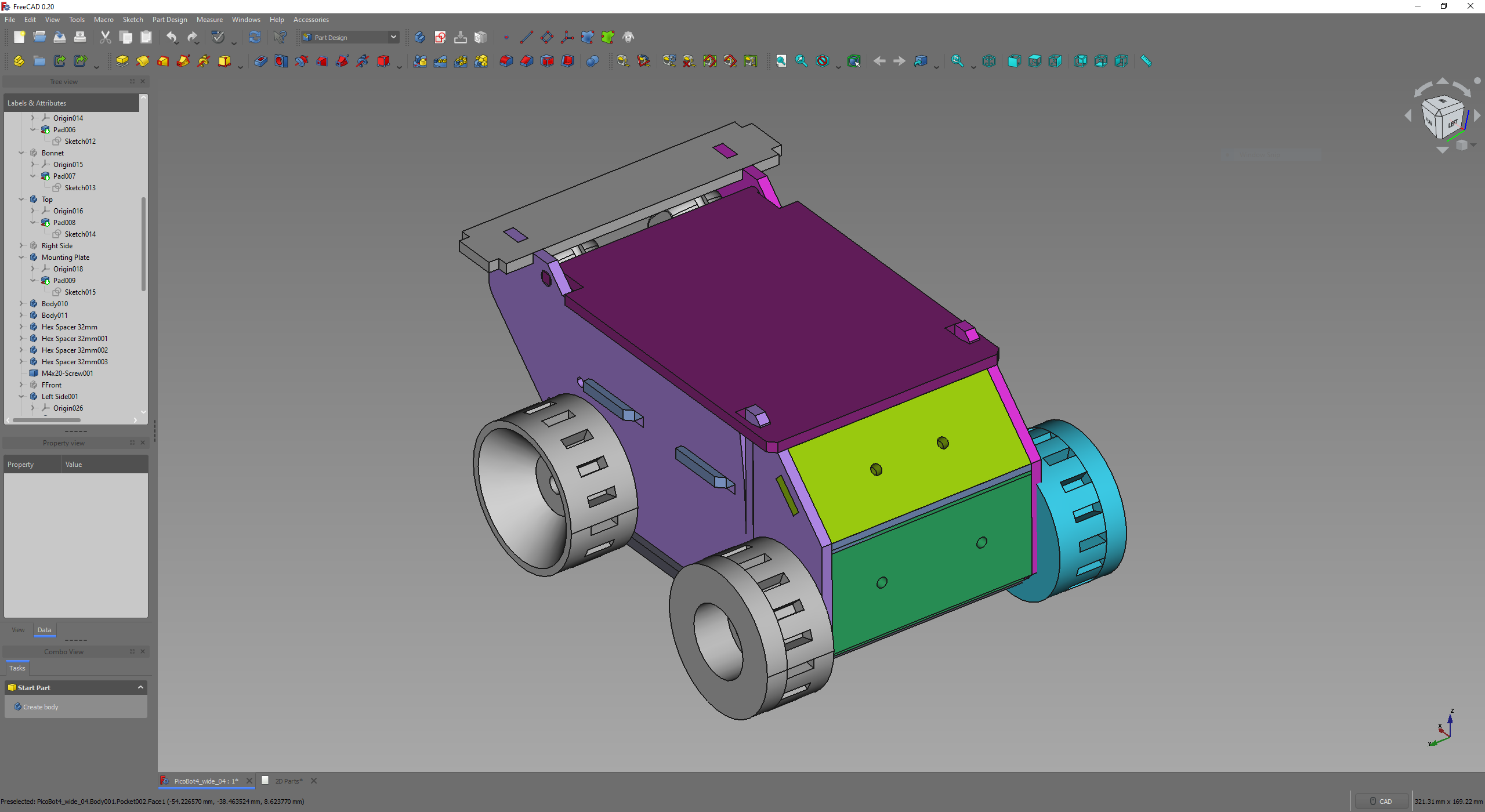
04/24/2023 at 21:10 • 0 commentsI've started designing the chassis in FreeCAD. I would like most of the parts to be laser cut, as this will be quick and cheap on the school's laser cutter, although they could also be 3D printed. Of course some parts, like the wheels would have to be 3D printed,
The design is not quite finished yet but I'll post the files here when they are.
Licence: Attribution-NonCommercial-ShareAlike 4.0 International (CC BY-NC-SA 4.0)
![]()
-
Test Drive
04/24/2023 at 20:50 • 0 commentsHere's a quick video showing the board in a tracked tank chassis - we use these as the base for a lot of our robots. It's controlled from a mobile phone over Wifi using Blynk. This chassis has more powerful motors than the ones I'm planning on using, so the H-Bridge is easily up to the job.
In future updates I'll post the code used for the moblie phone app, as well as other projects to get you up and running quickly.
-
The First PCB
04/24/2023 at 20:05 • 0 commentsSticking to the components that I already had, I set about designing a PCB using KiCad.
The micro controller I use here is the ESP32 based M5 Stamp Pico from M5 Stack. I like using this micro as it smaller than most of the other boards out there, so it will fit nicely in a Pi Zero sized footprint. Secondly, it has built in wireless programming using M5 Stack's UiFlow software. This is great for programming robots as you don't have to keep plugging them into your computer to upload new code. It also has just enough IO pins to do what I want it to do.
A slight drawback is that it doesn’t have a usb socket for programming (if you don't want to use UiFlow) – you'll need a separate usb-serial cable. Although this is not a deal breaker if it keeps the overall cost down. Unfortunately the Stamp Pico is quite pricey when it comes to ESP32 boards, It costs about $6.00, so I'll look into other options.
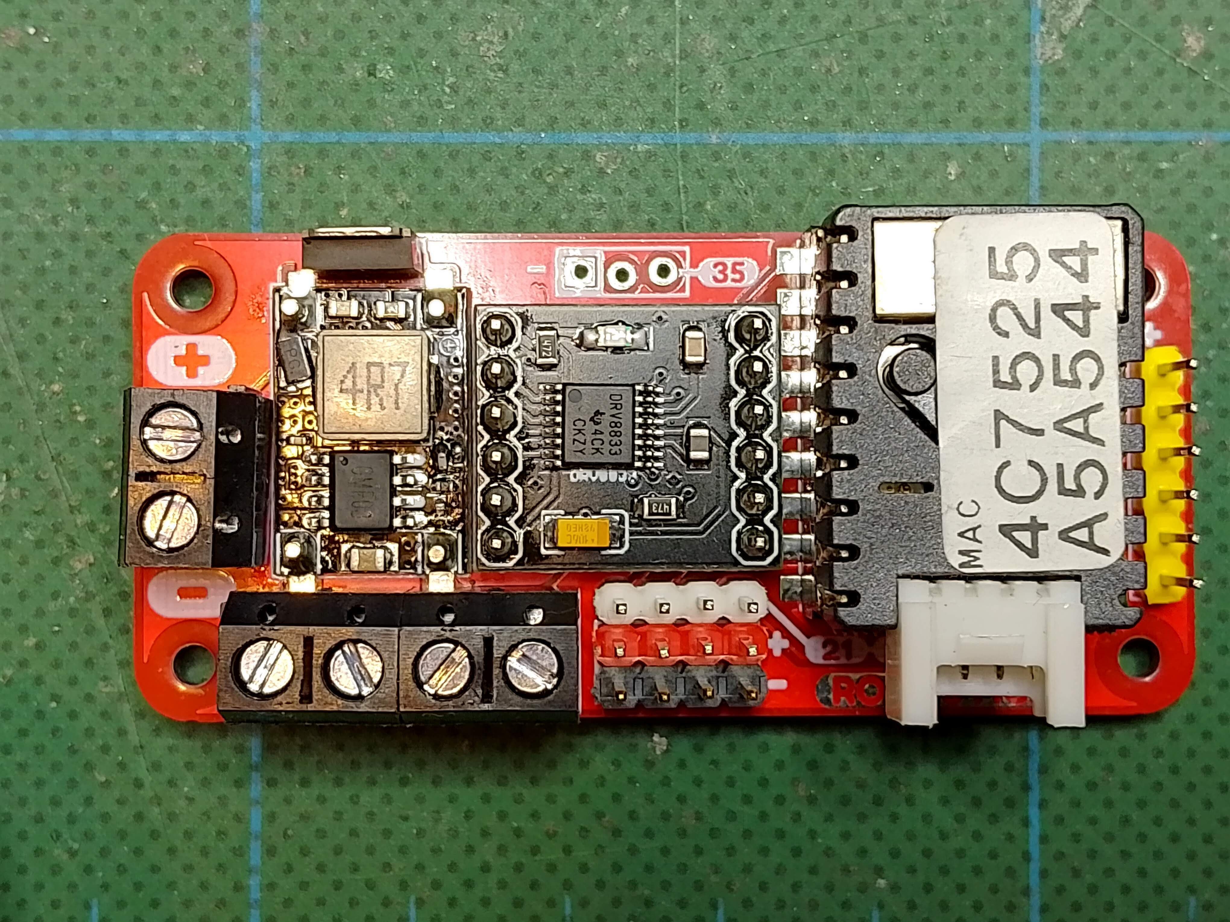
Here's a picture of the first iteration:
![]()
I'm pleased with how this came out as it met most of my requirements. There is a MOSFET above the DC/DC converter for reverse polarity protection. It's got screw terminals for the battery and motor connectors, and header pins for 4 servos or sensors. There is a 6-pin programming header on the right hand side of the board, for plugging in a USB to serial converter. The M5 Stamp module also has a 4 pin Grove connector – for 2 additional IO pins or I2C, so it's easy to add more devices.
$10 Robot!
A super cheap educational robotics platform. Everything you need to build and program a simple robot.