Guillermo Perez Guillen
-
6. Testing The Water Sprayer System
04/27/2023 at 07:04 • 0 commentsIn this section I will show you the programming of the Nicla Vision, and the MKR WAN 1310 in the Water Sprayer system. We will also test the prototype.
![image]()
Programming The Nicla Vision
Below I show you the code for the Nicla Vision board:
# AUTHOR: GUILLERMO PEREZ GUILLEN

import sensor, image, time, os, tf, pyb
from machine import Pin

pin0 = Pin("PG1", Pin.OUT_PP, Pin.PULL_UP)
pin1 = Pin("PG12", Pin.OUT_PP, Pin.PULL_UP)

redLED = pyb.LED(1) # built-in red LED
greenLED = pyb.LED(2) # built-in green LED

sensor.reset()                         # Reset and initialize the sensor.
sensor.set_pixformat(sensor.RGB565)    # Set pixel format to RGB565 (or GRAYSCALE)
sensor.set_framesize(sensor.QVGA)      # Set frame size to QVGA (320x240)
sensor.set_vflip(True)
sensor.set_hmirror(True)
sensor.set_windowing((240, 240))       # Set 240x240 window.
sensor.skip_frames(time=2000)          # Let the camera adjust.

labels, net = tf.load_builtin_model('bee_or_spider_v2')
found = False

def flashLED1(led): # Indicate with LED when target is detected
    found = True
    led.on()
    pin0.on()
    img.draw_string(5, 12, label)
    pyb.delay(1500)
    led.off()
    pin0.off()
    found = False


def flashLED2(led): # Indicate with LED when target is detected
    found = True
    led.on()
    pin1.on()
    img.draw_string(5, 12, label)
    pyb.delay(1500)
    led.off()
    pin1.off()
    found = False

clock = time.clock()

while not found:
    clock.tick()
    img = sensor.snapshot()
    for obj in tf.classify(net, img, min_scale=1.0, scale_mul=0.8, x_overlap=0.5, y_overlap=0.5):
        print("**********nPredictions at [x=%d,y=%d,w=%d,h=%d]" % obj.rect())
        img.draw_rectangle(obj.rect())
        predictions_list = list(zip(labels, obj.output()))
        for i in range(len(predictions_list)):
            confidence = predictions_list[i][1]
            label = predictions_list[i][0]
            print("%s = %f" % (label, confidence))
            if confidence > 0.8:
                if label == "bee":
                    print("It's a BEE")
                    #img.draw_string(5, 12, label)
                    flashLED1(greenLED)
                    #pin0.on()
                if label == "spider":
                    print("It's a SPIDER")
                    #img.draw_string(5, 12, label)
                    flashLED2(redLED)
                    #pin1.on()

    print(clock.fps(), "fps")
How does it work?
- This code is similar to the code from chapter 5. The bee, spider and unknow prediction scores are printed through the serial port;
- The conditional to activate the detection of a bee or a spider must be greater than 0.8;
- If the camera detects a bee, then the green LED lights for 2 seconds and prints the message "It's a BEE" on the serial port;
- Additionally, pin0 (PG1 port) turns ON for 1.5 seconds and then turns OFF;
- If the camera detects a spider, then the red LED lights for 2 seconds and prints the message "It's a SPIDER" on the serial port; and
- Additionally, pin1 (PG12 port) turns ON for 1.5 seconds and then turns OFF;
Troubleshooting and solution:
To make this script with MicroPython, I faced the problem of programming the output ports of the Nicla Vision since there is not enough information. Fortunately in the OpenMV discussion forum I found the solution: https://forums.openmv.io/t/controlling-gpio-pins-of-arduino-nicla-vision-board-using-openmv-ide/7533
Programming The MKR WAN 1310
Below I show you the code to upload to the MKR WAN 1310 board, but you can use any arduino board.
/*
AUTHOR: GUILLERMO PEREZ GUILLEN
*/

// We include the library to be able to control the servo
#include <Servo.h>

int Pin1 = 4;
int Pin2 = 5;

// We declare the variable to control the servo
Servo servoMotor;

int bee = 0;
int spider = 0;

void setup() {
  // We start the serial monitor to display the result
  Serial.begin(9600);
  // We start the servo so that it starts working with pin 6
  servoMotor.attach(6);
  pinMode(Pin1,INPUT);
  pinMode(Pin2,INPUT);
  // initialize the servo
  servoMotor.write(100);
  Serial.println("ITS BEE OR SPIDER?");
}

void loop() {
  if (digitalRead(Pin1)==HIGH){
    Serial.println("It's a BEE");
    bee++;
    Serial.print("BEE = ");
    Serial.println(bee);
    Serial.println("--------------------");
    delay(1500);
  }
  else if (digitalRead(Pin2)==HIGH){
    Serial.println("It's a SPIDER");
    spider++;
    Serial.print("SPIDER = ");
    Serial.println(spider);
    Serial.println("--------------------");
    servoMotor.write(175);
    delay(1500);
    servoMotor.write(100);
  }
  else {
    delay(200);
  }
}
How does it work?
- Pin1 (D4) is used to detect the bees, so a counter keeps track of the bees and prints it on the screen each time it is updated;
- Pin2 (D5) is used to detect the spiders, and in the same way a counter keeps track of the spiders and prints it on the screen each time it is updated;
- Additionally, the servo (D6) is activated to press the water sprayer for 1500 milliseconds and then release it.
Test
Below I show you a screenshot during the test carried out with this interesting prototype. You can appreciate the bee and spider counts displayed on the serial port.
![image]()
And a zoom to the water spray bottle when it emits a waterjet.
![image]()
Below I show you the video during the tests carried out.
I also show you a video capture on PC so you can see what is happening in detail.
-
5. Adding The Water Sprayer System
04/27/2023 at 07:00 • 0 commentsIn this section I will show you how to assemble the water sprayer system that I have designed for this project.
Schematic Diagram
First of all, we need to know how this system will be connected and its basic operation. Below I show you the schematic diagram:
![image]()
How does it work?
- If the Nicla Vision board detects a bee, then it turns ON the green LED and the PG1 pin for 1.5 seconds;
- If the MKR WAN 1310 board detects a pulse through pin 4, then it activates the bee counter, and prints the number of bees through the serial port;
- If the Nicla Vision board detects a wasp, then it turns ON the red LED and the PG12 pin for 1.5 seconds;
- If the MKR WAN 1310 board detects a pulse on pin 5, then it activates the servo motor and the wasp counter, finally prints the number of wasps through the serial port;
- When the servo motor is activated, it rotates from 105 to 170 degrees with the gripper to press the water spray bottle for 1.5 seconds, then returns to the initial position of 105 degrees.
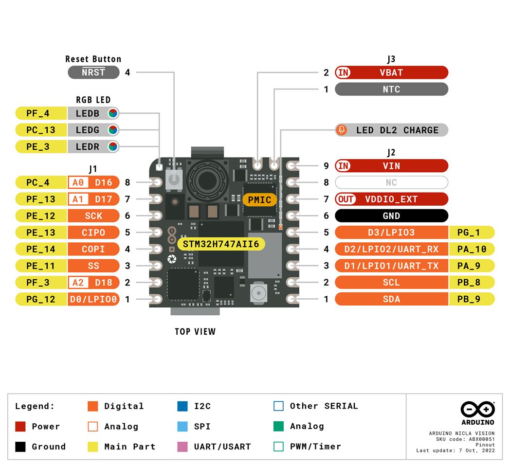
It's also necessary to know the pinout of the Nicla Vision and MKR WAN 1310 boards that I will use in my prototype.
Nicla Vision Pinout
![image]()
MKR WAN 1310 Pinout
![image]()
Assembling the device
Below I show you the gripper that we will use, as you can see it has a MG995 servo, which has a stall torque from 8.5 kgf·cm (4.8 V ) to 10 kgf·cm (6 V) . Here the datasheet: https://www.electronicoscaldas.com/datasheet/MG995_Tower-Pro.pdf
![image]()
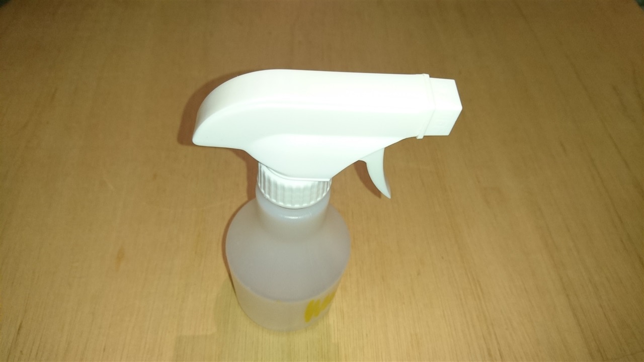
The handheld water sprayer is a generic 250 ml.
![image]()
I have mounted the devices on an old CD case, which is ideal since the water spray bottle doesn't stop the movement of the gripper when it works.
![image]()
But if you have enough time and filament to 3D print similar boxes, here are the STL files for you to modify and print. Below I show you module 1, which is an empty box on the inside and with the holes to insert the cables you need to connect a battery for example.
![image]()
Finally module 2. We can use this piece for the base of module 1 or to assemble the Nicla Vision. In my case, I fixed it using two rubber bands to hold the USB cable since the Nicla Vsion lacks holes to fix it with screws.
Here I show you a zoom of the handheld water sprayer mounted on the gripper using a single nylon strap.
![image]()
Now the Nicla Vision mounted in module 2, by means of the USB cable fixed with a couple of rubber bands.
![image]()
Finally the MKR WAN 1310 mounted on the opposite side of the Vision nicla and on module 2.
![image]()
Below I show you an image of the frontal view after wiring the Nicla Vision and MKR 1310 boards.
![image]()
And below I show you an image of the back view.
![image]()
![image]()
-
4. Testing The Machine Learning Model With OpenMV
04/27/2023 at 06:57 • 0 commentsIn this chapter I will show you the procedure to use OpenMV when we are going to test the machine learning model created with Edge Impulse on our Nicla Vision board.
Build the Firmware
Since the Nicla Vision doesn't have any on-board SRAM we need to build the machine learning model into the firmware and load it from the flash. To do so, go to https://github.com/openmv/openmv and fork the repository.
![image]()
Rename the machine learning model and the label file downloaded in Edge Impulse, in my case I renamed to bee_or_spider.tflite and bee_or_spider.txt respectively.
![image]()
In your fork, replace the built-in machine learning model under src/lib/libtf/models with the model you downloaded from Edge Impulse Studio. Commit the files and push the commit to the repository. It will build a new firmware automatically.
![image]()
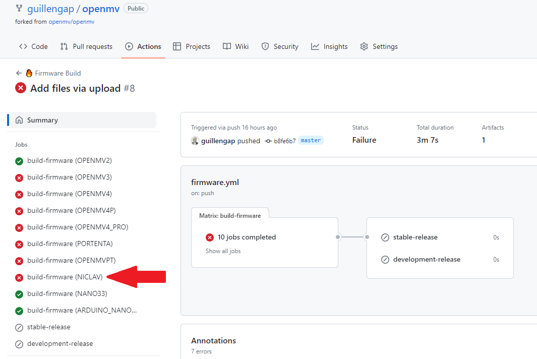
You can inspect the build process under "Actions". Once the firmware for NICLAV, has been built you can download it from the firmware link.
![image]()
Flash the Firmware
We can now return to OpenMV and flash the new firmware to the Nicla Vision.
![image]()
Put the Nicla Vision in bootloader mode by double-clicking the reset button – the green LED will start flashing. Click the Connect button in the IDE – the dialogue to Load a firmware shown below will open.
![image]()
Click OK, and navigate to bin file produced in the previous step and click Run.
![image]()
The Nicla Vision will be flashed with the new firmware, which includes the Edge Impulse model.
![image]()
In my case I uploaded my best machine learning model, which is 1.81 MB in size. In other words, I am using 90.5% of the flash memory of the Nicla Vision.
Run the Script
The next step is to write a Python script in OpenMV to control the Nicla camera and use the ML library to classify the image stream and try to detect our target objects. The video stream is just a series of image frames which are passed to a TensorFlow object which classifies the frame using the model and calculates a confidence prediction. The complete script of the classification example is as follows:
# AUTHOR: GUILLERMO PEREZ GUILLEN

import sensor, image, time, os, tf, pyb

redLED = pyb.LED(1) # built-in red LED
greenLED = pyb.LED(2) # built-in green LED

sensor.reset()                         # Reset and initialize the sensor.
sensor.set_pixformat(sensor.RGB565)    # Set pixel format to RGB565 (or GRAYSCALE)
sensor.set_framesize(sensor.QVGA)      # Set frame size to QVGA (320x240)
sensor.set_vflip(True)
sensor.set_hmirror(True)
sensor.set_windowing((240, 240))       # Set 240x240 window.
sensor.skip_frames(time=2000)          # Let the camera adjust.

labels, net = tf.load_builtin_model('bee_or_spider_v2')
found = False

def flashLED(led): # Indicate with LED when target is detected
    found = True
    led.on()
    pyb.delay(2000)
    led.off()
    found = False

clock = time.clock()

while not found:
    clock.tick()
    img = sensor.snapshot()
    for obj in tf.classify(net, img, min_scale=1.0, scale_mul=0.8, x_overlap=0.5, y_overlap=0.5):
        print("**********nPredictions at [x=%d,y=%d,w=%d,h=%d]" % obj.rect())
        img.draw_rectangle(obj.rect())
        predictions_list = list(zip(labels, obj.output()))
        for i in range(len(predictions_list)):
            confidence = predictions_list[i][1]
            label = predictions_list[i][0]
            print("%s = %f" % (label, confidence))
            if confidence > 0.8:
                if label == "bee":
                    print("It's a BEE")
                    img.draw_string(5, 12, label)
                    flashLED(greenLED)
                if label == "spider":
                    print("It's a SPIDER")
                    img.draw_string(5, 12, label)
                    flashLED(redLED)

    print(clock.fps(), "fps")
How does it work?
- The bee, spider and unknow prediction scores are printed through the serial port;
- The conditional to activate the detection of a bee or a spider must be greater than 0.8;
- If the camera detects a bee, then the green LED lights for 2 seconds and prints the message "It's a BEE" on the serial port; and
- If the camera detects a spider, then the red LED lights for 2 seconds and prints the message "It's a SPIDER" on the serial port.
Test
Below I show you an image capture when the camera has detected a bee.
![image]()
Also, below I show you an image capture when the camera has detected a spider.
![image]()
Below I show you the tests carried out with my model created with Edge Impulse and OpenMV. As you can see, I did the tests with images of a bee and a spider printed on a cardboard card.
-
3. Improving Edge Impulse Model
04/27/2023 at 06:54 • 0 commentsIn this post I will show you how to improve my first model that I made in Edge Impulse. As you will remember, I obtained an accuracy of 70.5% and a loss value of 0.89.
Reporting a Bug in OpenMV
If I increase the number of images samples, we can increase the accuracy scores and reduce loss value, however the size model will be increase above 2 MB. Remember that the flash memory of the Nicla Vision is 2 MB. The idea is to load the model in the flash memory because if we use the ROM memory to load the model and run the code, this will not work.Below I show you an error report that I had when I increased the number of samples.
![image]()
So that you understand me, here are the details of the bug that I reported to technical support of OpenMV: https://forums.openmv.io/t/openmv-cant-build-a-new-firmware-for-nicla-vision/8200
Selecting Best Samples
Since we are limited by the memory of the Nicla Vision, Then my strategy is to select the best images loaded in my project and reorganize it.
![image]()
When I talk about choosing the best images, I mean the ones with the best details, and with backgrounds of different colors. Blurred and cropped images must be removed. Below you can see samples of images of bees, spiders and unknown images that I used to train my model.
![image]()
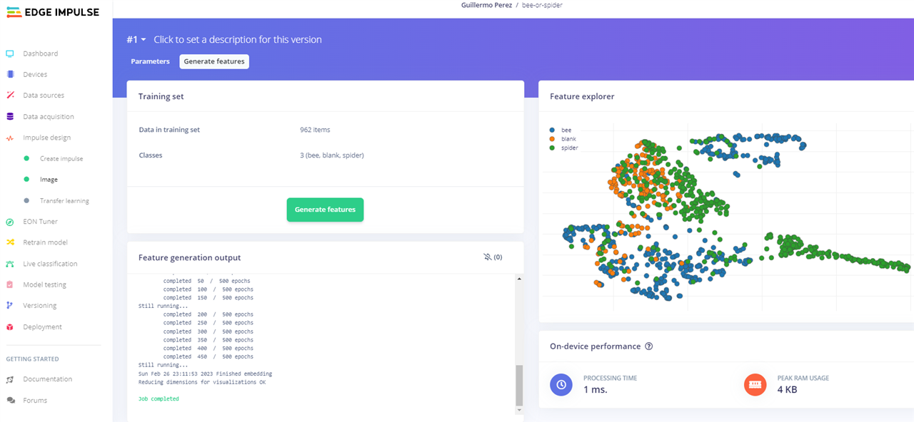
Below I show you the features generated after these changes. As you can see, the three classes are bee, spider and unknown.
![image]()
Training the Model
We retrain the model and see that we get better results. now the accuracy is 74.1% and the loss value is 0.58.
![image]()
With the changes made we have increased the accuracy from 70.5% to 74.1%. We have also reduced the loss value from 0.89 to 0.58. Therefore we have improved and now we can test this model on our Nicla Vision board.
Model Testing
Edge Impulse has a facility to test the model created with the uploaded dataset. Below I show you the results and you can see a good accuracy of 81.69%, which is a good indicator for our purposes.
![image]()
OpenMV Library
- Now that we have a Machine Vision model that works, we can use EdgeImpulse to generate an OpenMV library that can be flashed to the Nicla Vision and be called from a Python script.
- As we saw in the previous chapter, Select Deployment from the menu bar, choose OpenMV from the library section, and click Build
- This will build the file, then open a file browser to input the download location – you will get the zip archive.
![image]()
Once downloaded the compressed file in zip format, below I show you the model files.
![image]()
-
2. Edge Impulse
04/27/2023 at 06:52 • 0 commentsIn this post I will show you the first approaching to Edge Impulse to implement it in my project. Edge Impulse provides the ultimate development experience for ML on embedded devices for sensors, audio, and computer vision, at scale. It enables the deployment of highly-optimized ML on hardware ranging from MCUs to CPUs and custom AI accelerators.
![image]()
All Edge Impulse developed algorithms are licensed under Apache 2.0, without royalties. This means that you completely own your algorithms, and no royalties exist when it comes to deploying them. For Developer Community, I opened Free account for individual developers which is used to deploy innovative ML on any edge device. Project main features: 20 min per job, and 4GB or 4 hours of data per project. Here you can open the account: https://www.edgeimpulse.com/
Once we enter the account, I have created the "bee-or-spider" project which will help me to detect a bee or a spider, we simply click on the "Create new project" icon as shown below.
![image]()
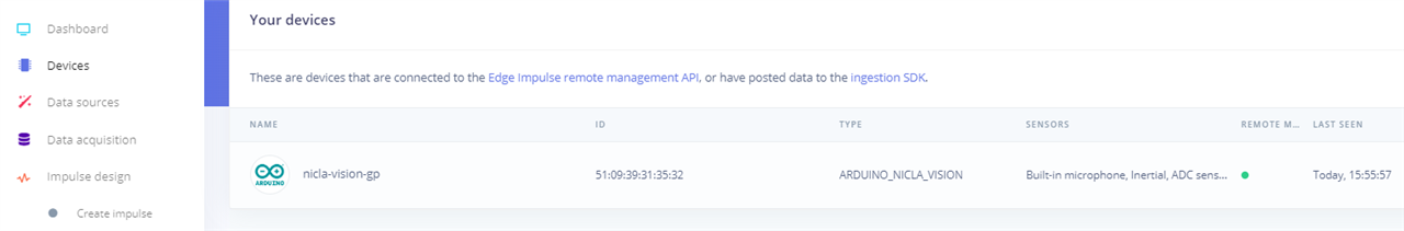
Adding Devices
In the "Devices" tab I have connected the Arduino Nicla Vision board as shown below.
![image]()
Arduino CLI Installation
How to connect the device? I followed the steps indicated in the official documentation at this link: Arduino Nicla Vision
I installed Edge Impulse CLI Windows version. All the steps to install Edge Impulse CLI you can find here: Edge Impulse CLI
Another option to Install Arduino CLI with pre-built binaries: Arduino CLI
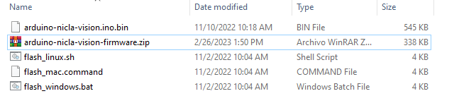
Here I show you the downloaded files:
![image]()
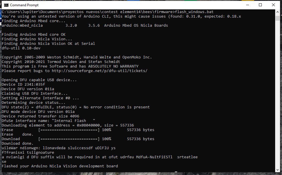
Open command prompt and run "flash_windows.bat".
![image]()
We can check the installation by running: "arduino-cli" as shown below
![image]()
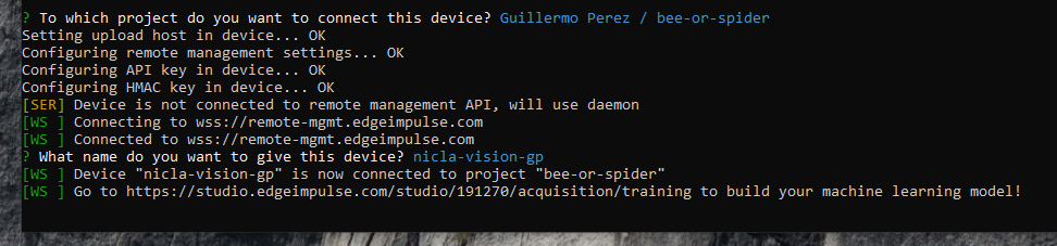
Once the Arduino CLI is installed, you can connect to edge impulse with the command edge-impulse-daemon. I type my username and password, and once the Nicla Vision device is connected I choose the "bee-or-spider" project.
![image]()
Finally, the system asks me what name I want to give to the connected device? I wrote "nicla-vision-gp"
![image]()
Now the device is ready to use the Arduino CLI.
![image]()
Data Acquisition
A good training model with Machine Learning needs a lot of images, hundreds or maybe thousands of photos. In addition, the images must be different, and its not possible to put repeated images. I got a lot of dataset bee and spider images on the kaggle website
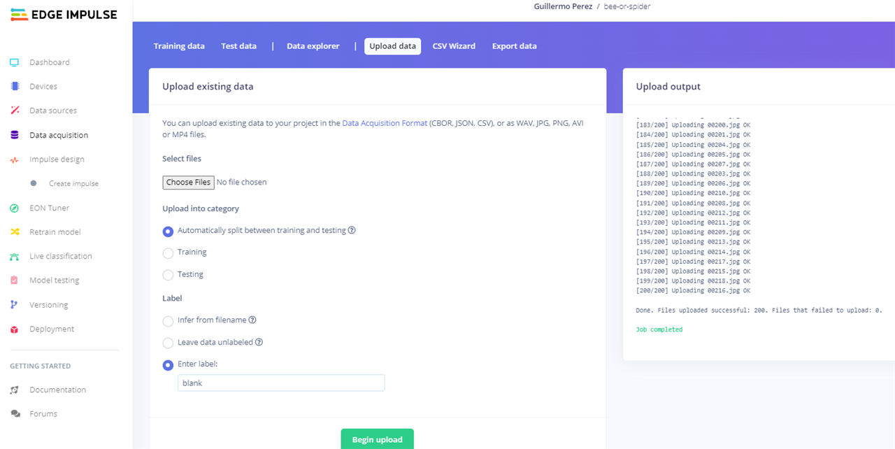
There are two ways to upload images to the project created in Edge Impulse, the first is using the tab tool: Upload data - Upload existing data
![image]()
The other method is to use OpenMV with the tab: Tools - Dataset Editor - Export - Login to Edge Impulse Account and Upload to Project
![image]()
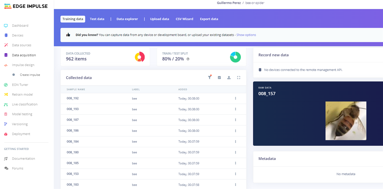
Here I show you the image class called: bee
![image]()
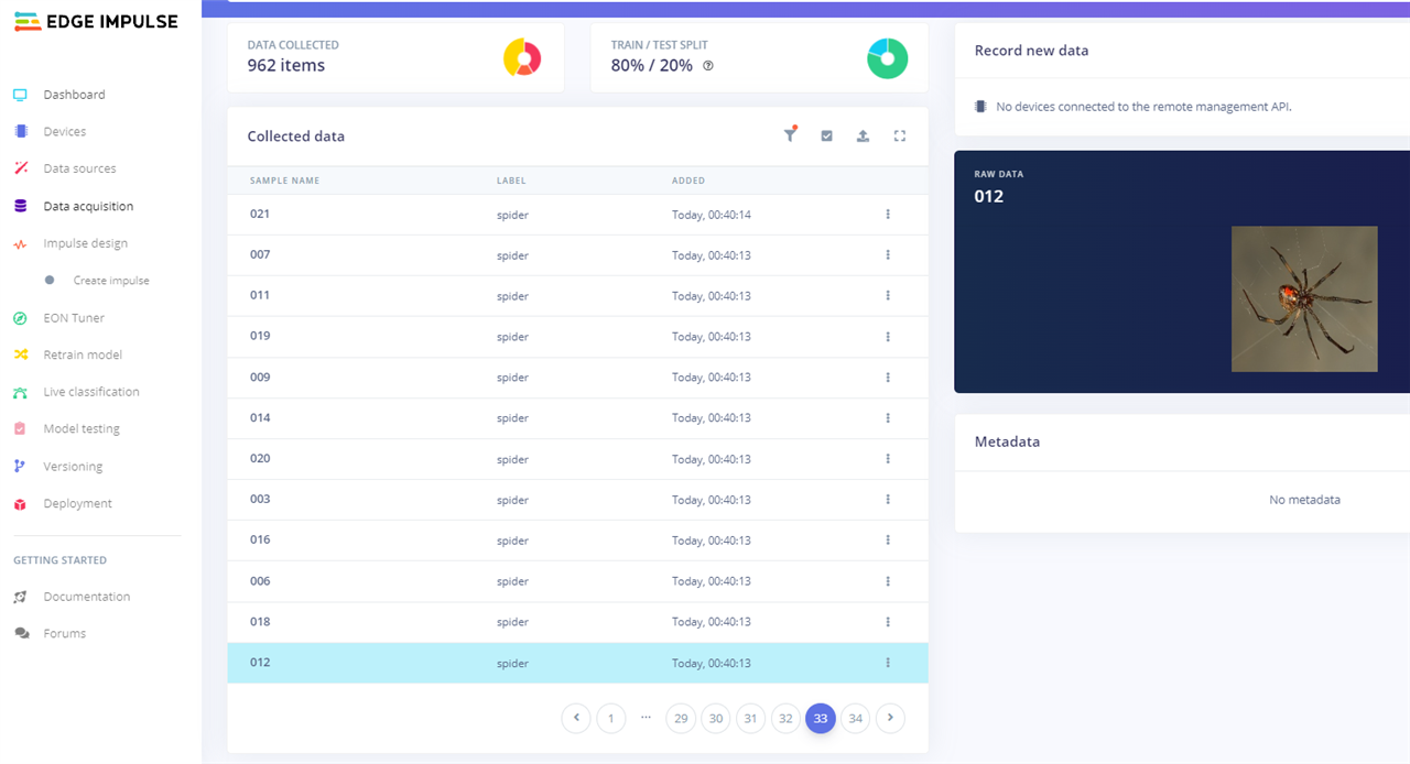
Now, the image class called: spider
![image]()
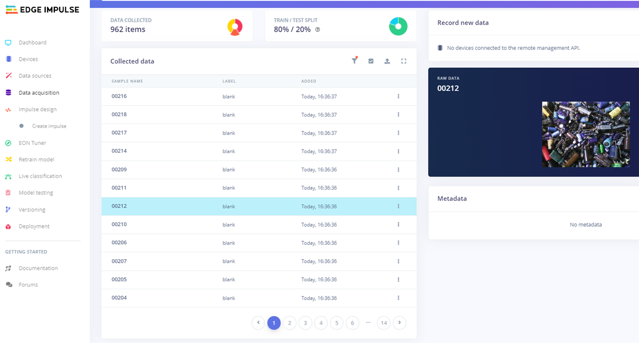
And finally the image class called: blank, which helps us to identify any object that is not a bee or a spider.
![image]()
In total I uploaded 1200 images as follows: 500 images of the bee class, 500 images of the spider class, and 200 images of the blank class.
For the system to generate a good model, it is necessary to use 80% of the images as training and 20% as test.Impulse Design - Create Impulse
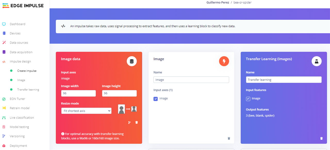
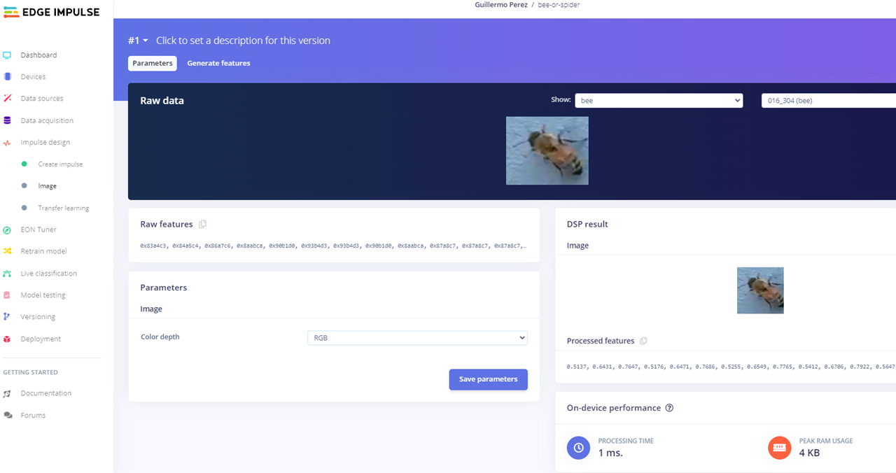
In the "Impulse design" tab, we open the "Create Impulse" section. We leave the default values of the Image data resource of 92x96 pixels. Add the resources "Image" and "Transfer Learning (Images)" as shown below. Finally click on the "Save Impulse" button
![image]()
Create Impulse - Image
Now we open the "Image" section to verify the images of the classes and click on the upper section "Generate features"
![image]()
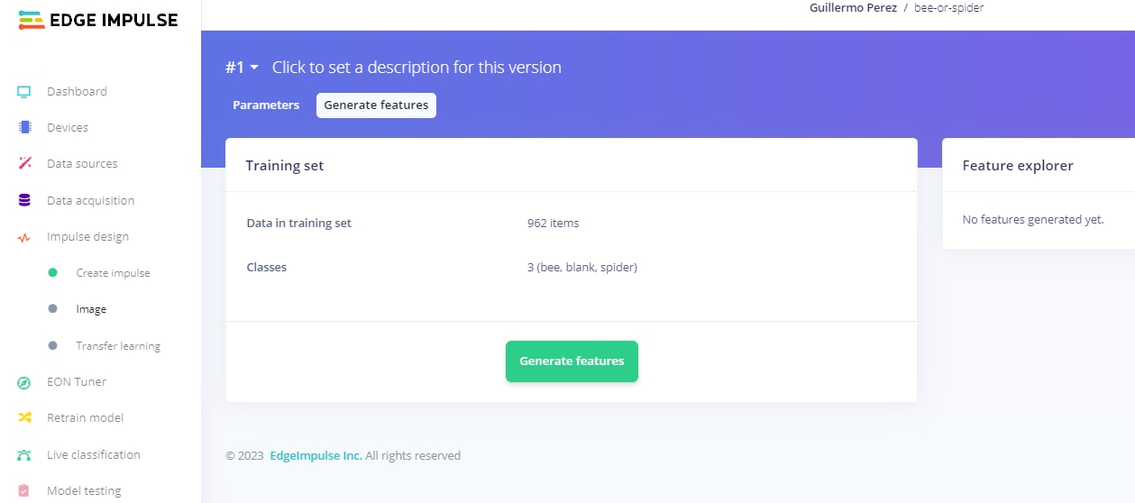
Click on the "Generate features" button
![image]()
After a few minutes the next features are generated.
![image]()
Impulse design - Transfer learning
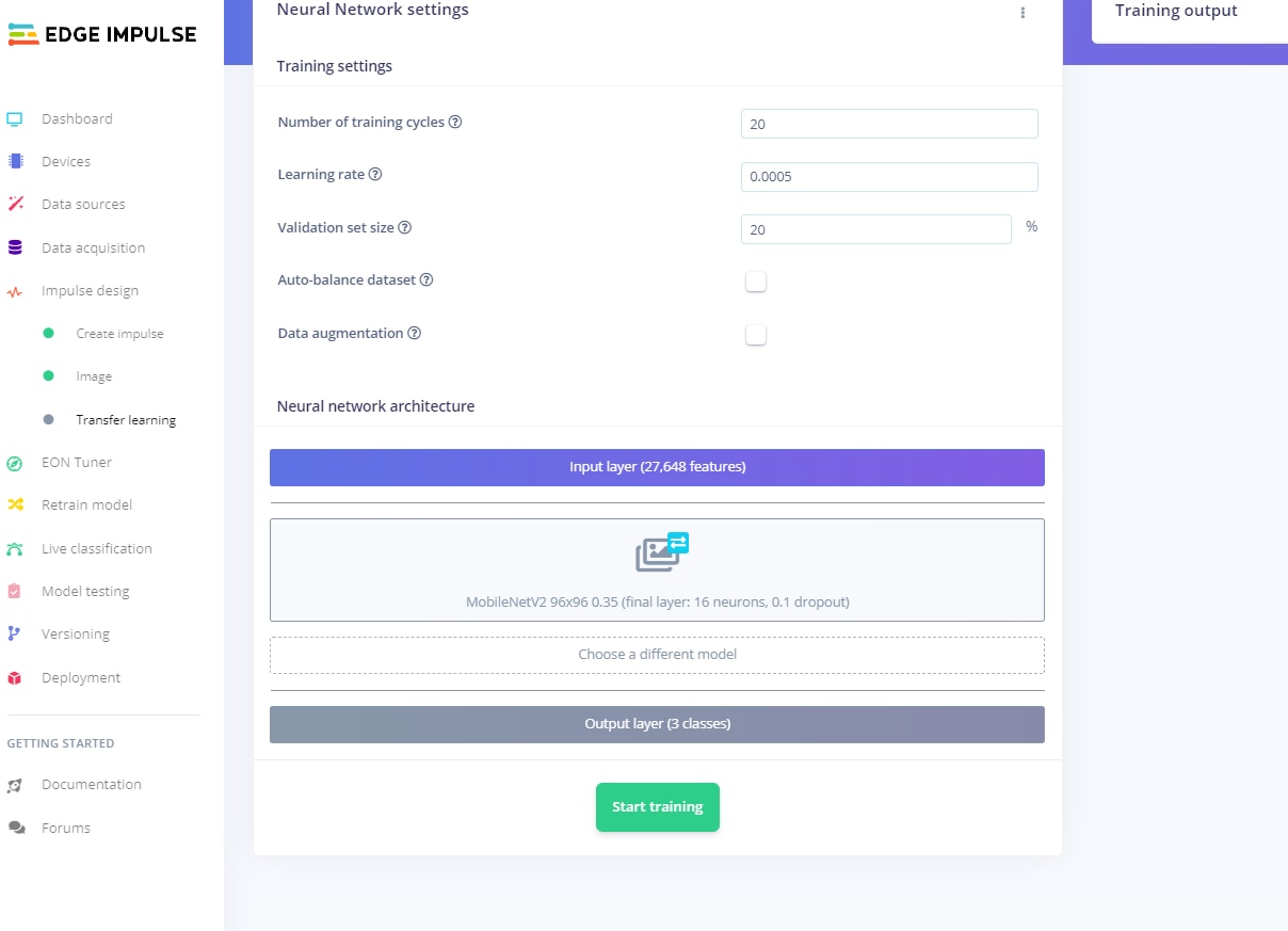
Now we open the "Transfer learning" section and leave the default values.
![image]()
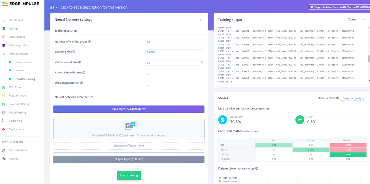
Click on the "Start training" button and after a few minutes the following training model is generated.
![image]()
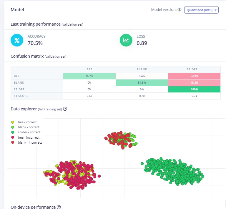
As we can see there is a precision of 70.5% and a loss value of 0.89. This means that its an average model, that is to say that its not good but its not bad either, so it needs changes to improve the model, and I will make these changes later. In the confusion matrix describes the performance of the classification model, and I can figure out where changes need to be made to improve the model.
![image]()
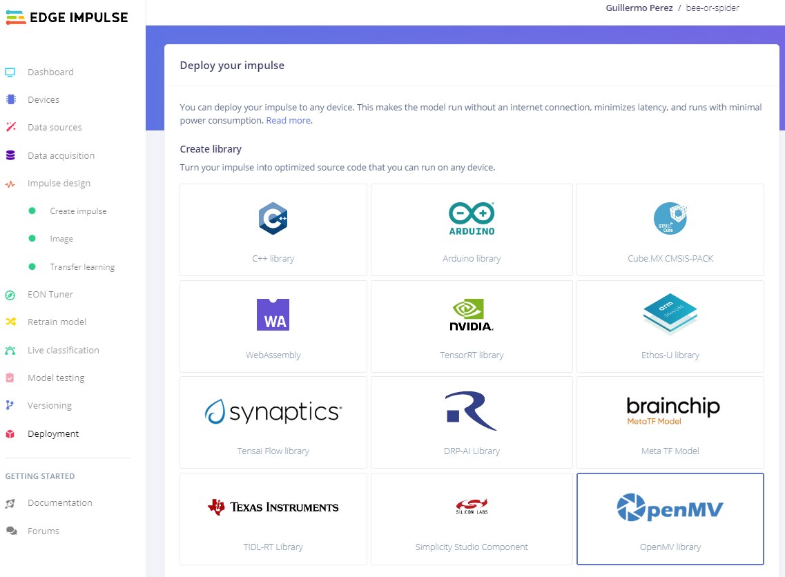
Deployment
Finally we go to the "Deployment" tab. Here I select to create the "OpenMV" library and click on the "Build" button.
![image]()
After a few minutes, the library is successfully generated and the next message opens:
![image]()
The library is automatically downloaded to our PC computer (ei-bee-or-spider-openmv-v1.zip).
-
1. Getting Started
04/27/2023 at 06:49 • 0 commentsIn this post I will show you the basic configuration of the Arduino Pro Nicla Vision and Arduino MKR WAN 1310 programming boards.
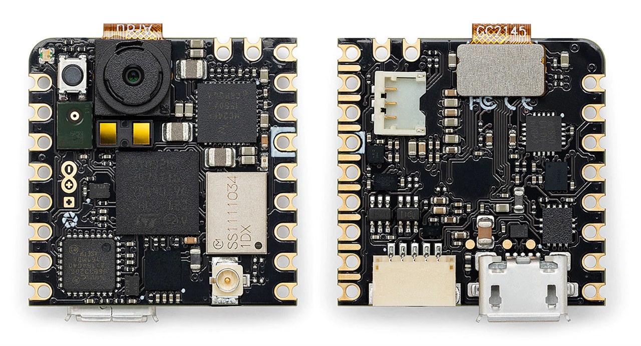
Nicla Vision Setup
The Arduino Nicla Vision board is a ready-to-use, standalone camera for analyzing and processing images on the edge. Thanks to its 2MP color camera, smart 6-axis motion sensor, integrated microphone and distance sensor, it is suitable for asset tracking, object recognition and predictive maintenance.
![image]()
In my case I configure my board with Arduino IDE version 1.8; wow we need to navigate to Tools > Board > Board Manager.
![image]()
This will open up a new window, with all available cores. Find the one named Arduino Mbed OS Nicla Boards and install it.
![image]()
When it is finished, it should say
"INSTALLED"under the title. Exit the board manager, and go to Tools > Board > Arduino Mbed OS Nicla Boards. Here you can see all the Mbed boards listed, where you can select the board you are using. You have now successfully installed the core.![image]()
On Nicla Vision you can test an example code. So when you have selected the USB connection port of your board, please use the File > Examples > Nicla_Sense_System > Blink_Nicla
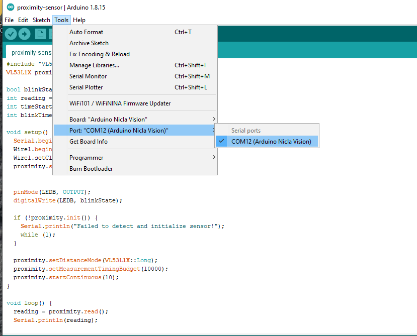
In my case, I successfully tested the Proximity Detection with Arduino Nicla Vision example. Below I show you the code:
#include "VL53L1X.h"
VL53L1X proximity;

bool blinkState = false;
int reading = 0;
int timeStart = 0;
int blinkTime = 2000;

void setup() {
  Serial.begin(115200);
  Wire1.begin();
  Wire1.setClock(400000); // use 400 kHz I2C
  proximity.setBus(&Wire1);


  pinMode(LEDB, OUTPUT);
  digitalWrite(LEDB, blinkState);

  if (!proximity.init()) {
    Serial.println("Failed to detect and initialize sensor!");
    while (1);
  }

  proximity.setDistanceMode(VL53L1X::Long);
  proximity.setMeasurementTimingBudget(10000);
  proximity.startContinuous(10);
}

void loop() {
  reading = proximity.read();
  Serial.println(reading);

  if (millis() - timeStart >= reading) {
    digitalWrite(LEDB, blinkState);
    timeStart = millis();

    blinkState = !blinkState;
  }
}
Here the VL53L1X library for Arduino
In my case the connection was via USB 2.0 through the COM12 port
![image]()
You can see the demonstration in the video below:
Using the Nicla Vision Camera
Finally, we will test the camera of the Nicla Vision board. First we download the OpenMV IDE application here: https://openmv.io/pages/download
![image]()
This software has many resources to program with python and examples like snapshot, machine learning, image processing, etc. In my case I took a snapshot. which I show below.
![image]()
Nicla vision module is working well. If you are looking for more details of what I just did, then here is a link: https://docs.arduino.cc/tutorials/nicla-vision/getting-started
Arduino MKR WAN 1310 Setup
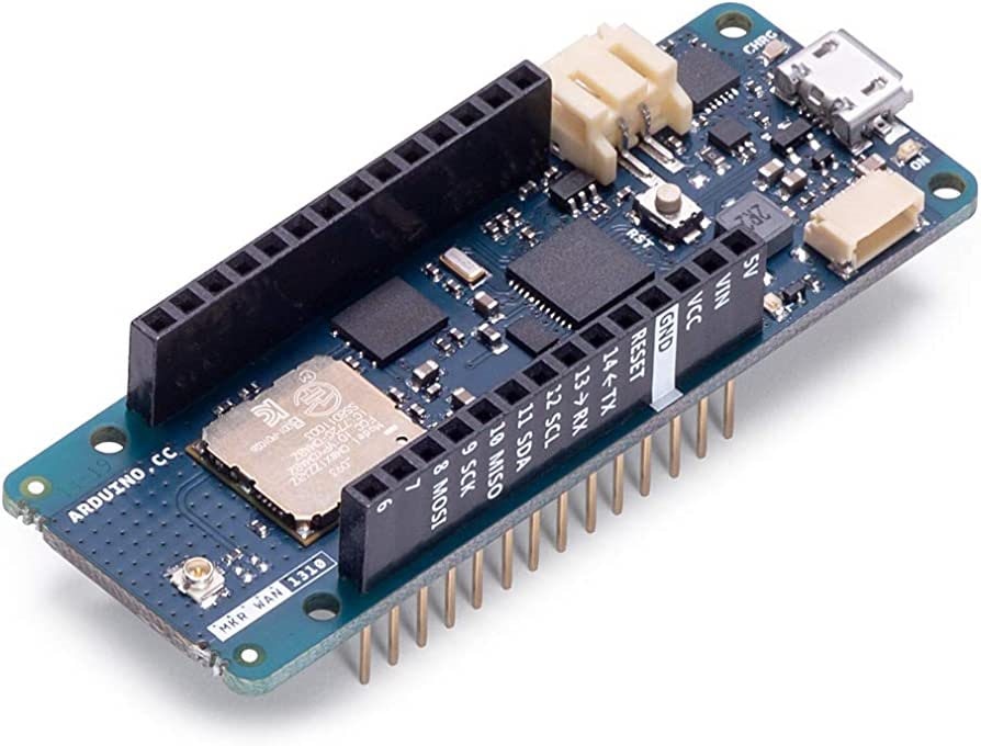
The Arduino MKR WAN 1310 provides a practical and cost effective solution to add LoRa connectivity to projects requiring low power. This open source board can connect to the Arduino IoT Cloud, your own LoRa network using the Arduino LoRa PRO Gateway, existing LoRaWAN® infrastructure like The Things Network, or even other boards using the direct connectivity mode.
![image]()
Here we need to navigate to Tools > Board > Board Manager.
This will open up a new window, with all available cores. Type in
"samd"in the search field, and install the Arduino SAMD Boards (32-bits ARM Cortex-M0+) core.![image]()
In my case update the library to version 1.8.13
When it is finished, it should say
"INSTALLED"under the title.Exit the board manager, and go to Tools > Board > Arduino SAMD Boards (32-bits ARM Cortex-M0+). Here you can see all the SAMD boards listed, where you can select the MKR board you are using. You have now successfully installed the core.
![image]()
When you have selected the USB connection port of your board, you are now ready to start using your board! The easiest way to check that everything is working, is to upload just a simple blink example to your board. This is done by navigating to File > Examples > 01.Basics > Blink.
Smart Insect Repellent System
Using Machine Learning To Detect And Repel Dangerous Insects