This log might be long. Unconvinced about the coaxialiser geometry suggested in the previous log, I set out to look for some kind of simulation software.
Blender
My idea was to look into how people simulate honey, a viscous liquid, and go from there. Nozzleboss used paint in a transparent 3D print before getting it printed in aluminium, so I figured I could so something similar digitally.
Briefly saw DPlisHSPlasH and then found FLIP Fluids:
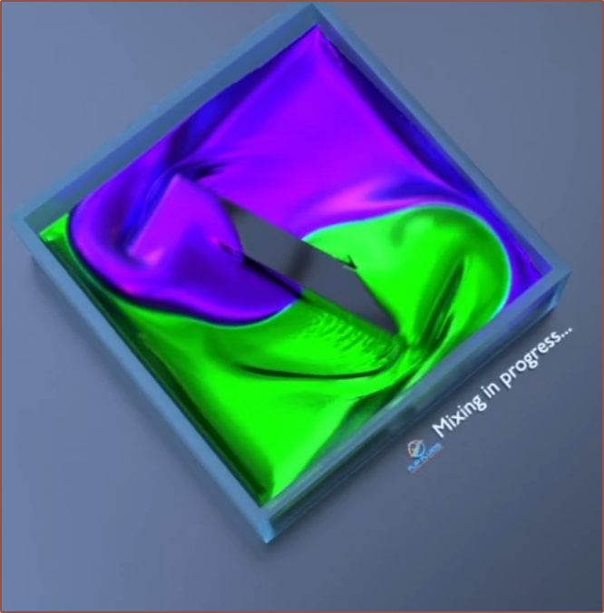
So I proceed to go through Blender Donut Tutorial 4.0, trying to learn just enough to be able to follow a fluid tutorial.
Eventually, I found out that I might not be able to simulate 2 different material or get cross-sectional views as I heard FLIP Fluids only simulates the surface of materials.
Ondsel ES CfdOF Workbench + Paraview setup
Decided to go with Ondsel for their nicer set of defaults, meaning I could get straight into installing the CfdOF toolchain as written on the wiki page and the latest MPI version of Paraview (5.13 RC2).
Somehow, I installed 2106 of OpenFOAM, which ES said was outdated when running the dependency checker. I just installed it using the "Install OpenFOAM" button under it, installing it in Appdata/Roaming like the standalone installer. The wiki says to avoid saving it in Program Files due to UAC.
Test Simulation
Now with that done, I started setting up the simulation. I was following these tutorials:
I started with the Coaxial8or R0 geometry since it's already been verified in real life.
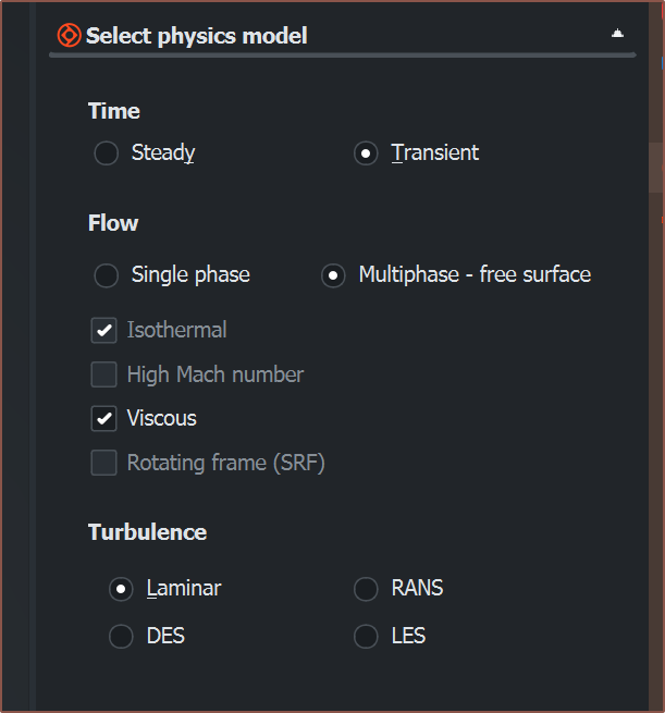
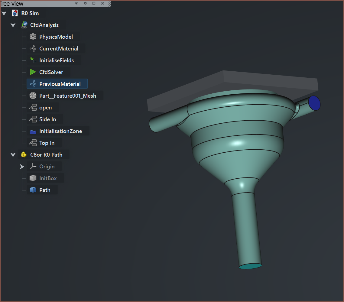
After removing the spaces from my boundary names and getting a mesh size small enough to work (0.25mm not the 1mm I started with), I had a simulation:
It was worrying when Paraview opened up with an error, but it can just be closed and then visibility enabled for OpenFOAMReader1 to see the results.

I'd later find out that it helps to disable and re-enable "Skip Zero Time" and then press "Apply" so that all time points are loaded in.
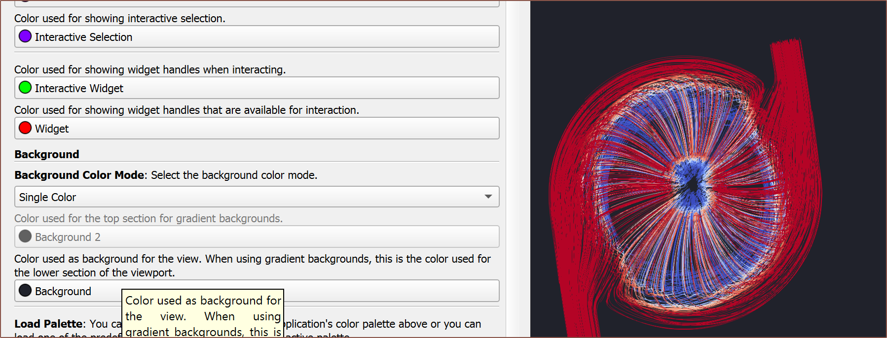
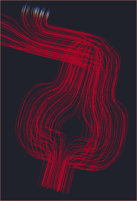
Then I added a stream, enabled point cloud, made it large enough for the sphere to encapsulate the model and lastly increased the amount of points, I had this:

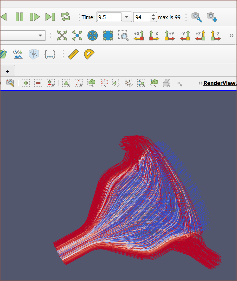
Made the background darker to increase contrast:
And this is the exist cross section I obtained:
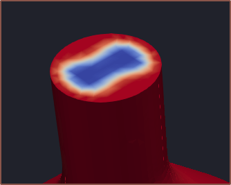
This does seem to agree with the 3D printed test results I got.
I also tried adding 2 planes and reducing the points to get a better look at the data:
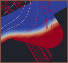
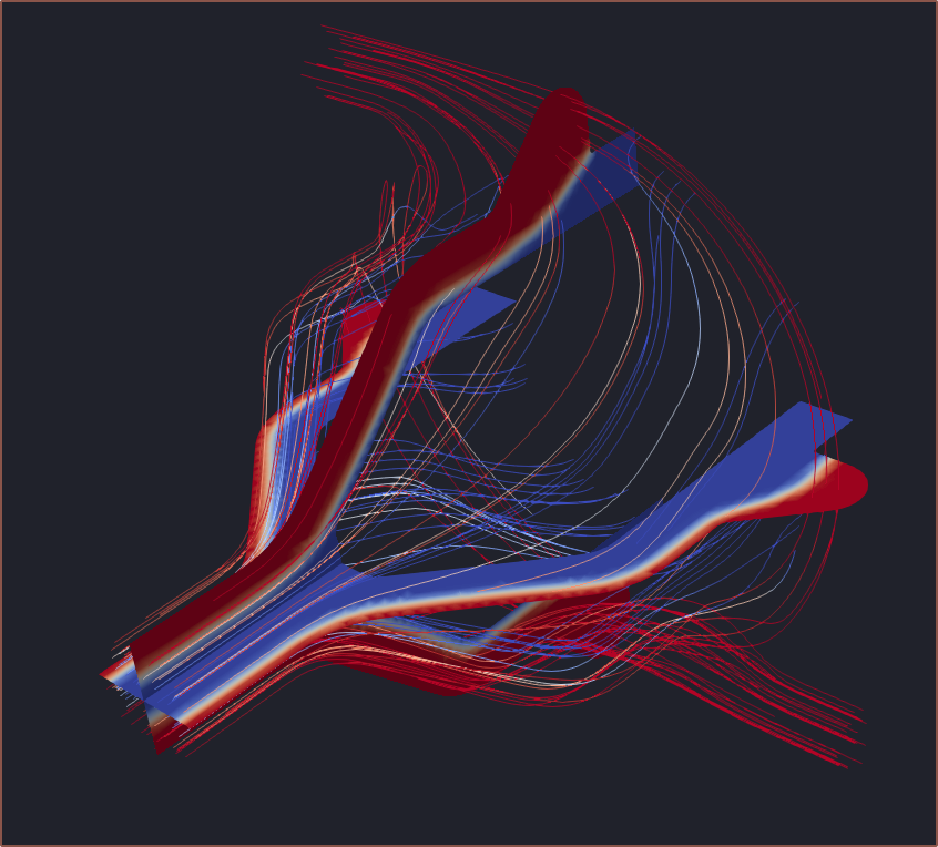 As expected, the new material does bulge into the space:
The proposed dual-coaxialiser geometry
First I looked to find a viscosity I liked for the simulation.
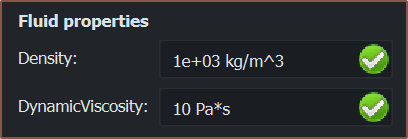
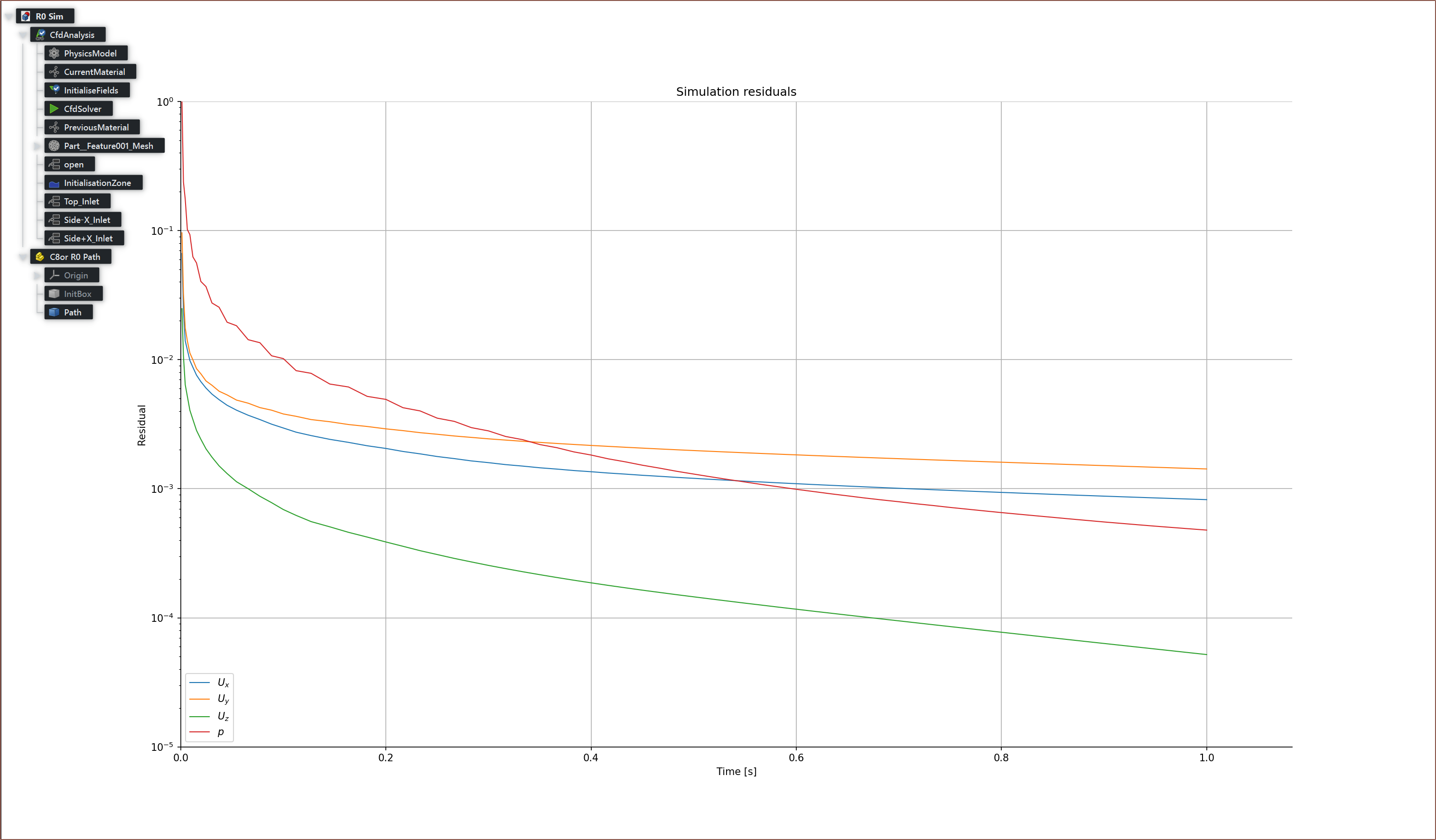
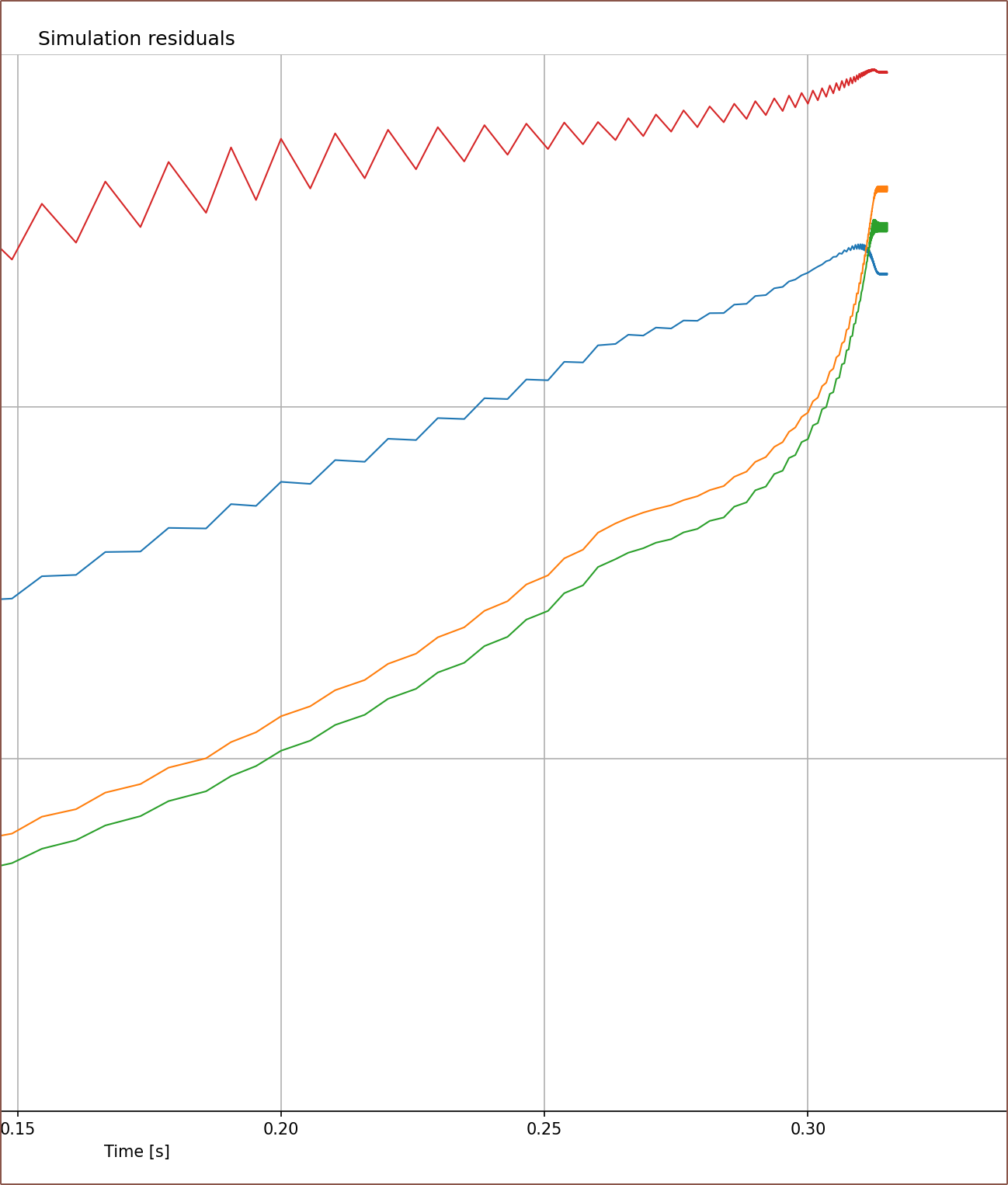 These are bad. If the residuals get this high, the simulation slows to a crawl. The mesh size is the issue, unexpectedly enough.
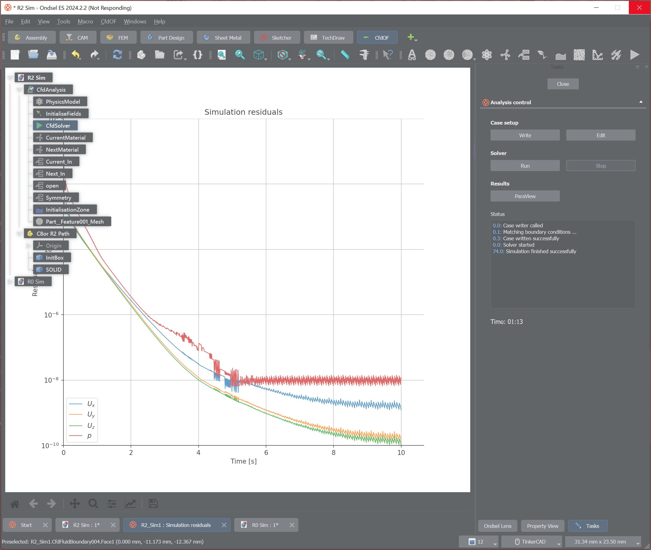 There's also the issue where something will still be calculating in the background even when the simulation is finished. Task manager shows this. I probably should report this as a bug but whether it's an ES or OpenFOAM issue is something I don't know. I think this happens maybe 10% of the time? It's not too bad tho since I can restart ES and then press the ParaView button since all the data was already saved.
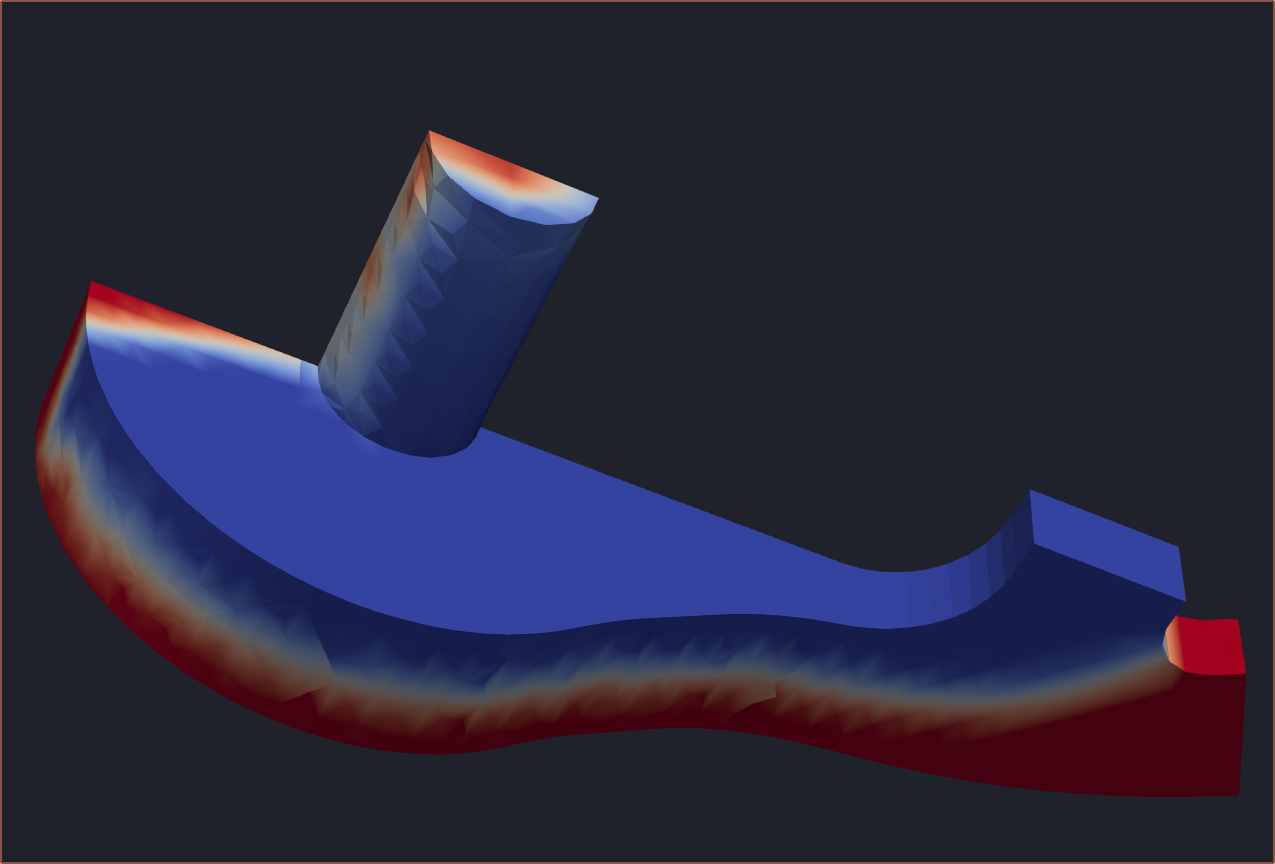

And there it is. A simulation.
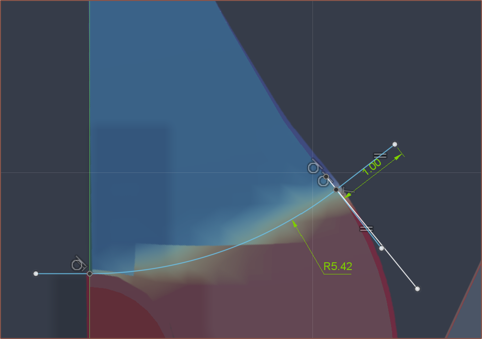 This is the path the new material followed until it hit the output tube.
Trying slightly different geometry
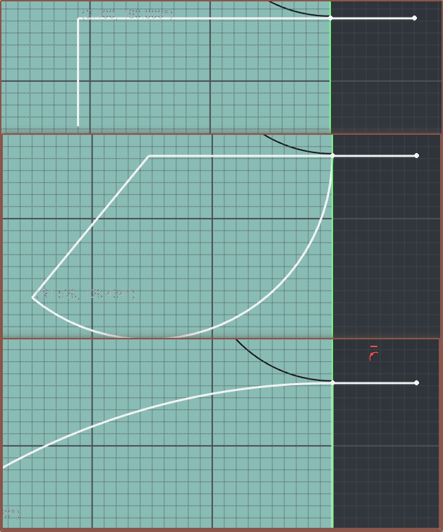
The polyline tool in ES is nifty:
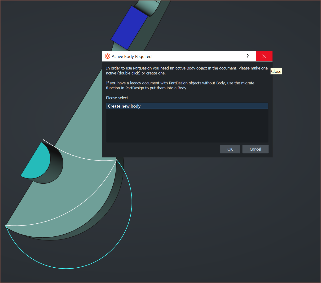
 Unfortunately, editing a STEP really is not:
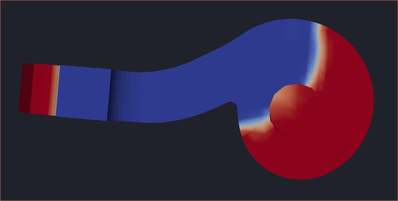
Tried a blower design, but I kinda expected the result to happen too, going off the time I tried simulating in Fusion:
Merging 8 inputs before coaxialiser
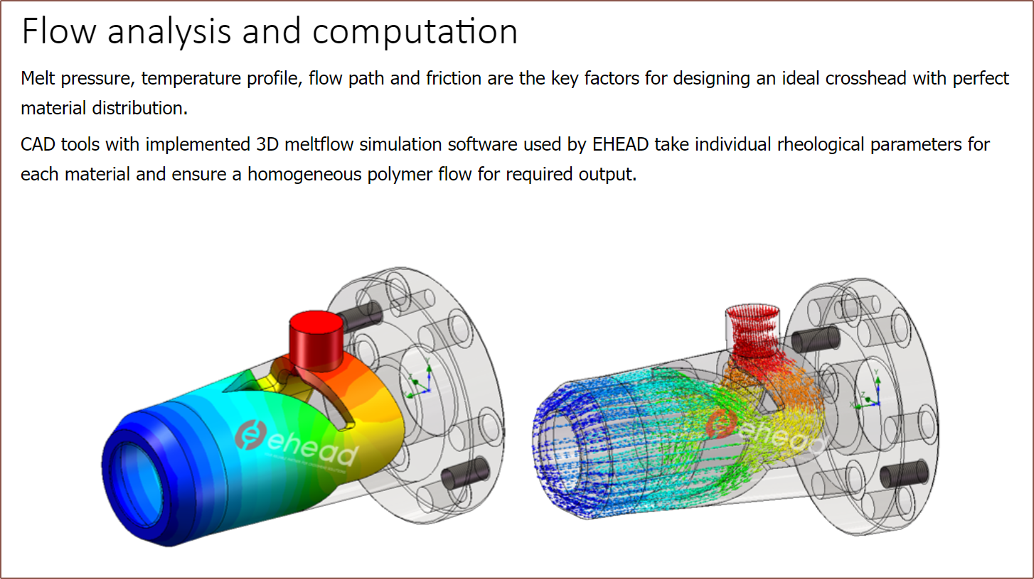
The idea was to have a single, larger coaxialiser that looked like that one simulation geometry I saw a while ago:
The idea was that this moves the output tube from a point along the NextMaterial ripple to a distant plane that just so happened to be curved into a torus.
First thing was to tweak the inputs:
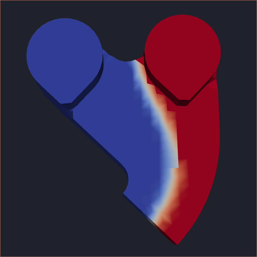
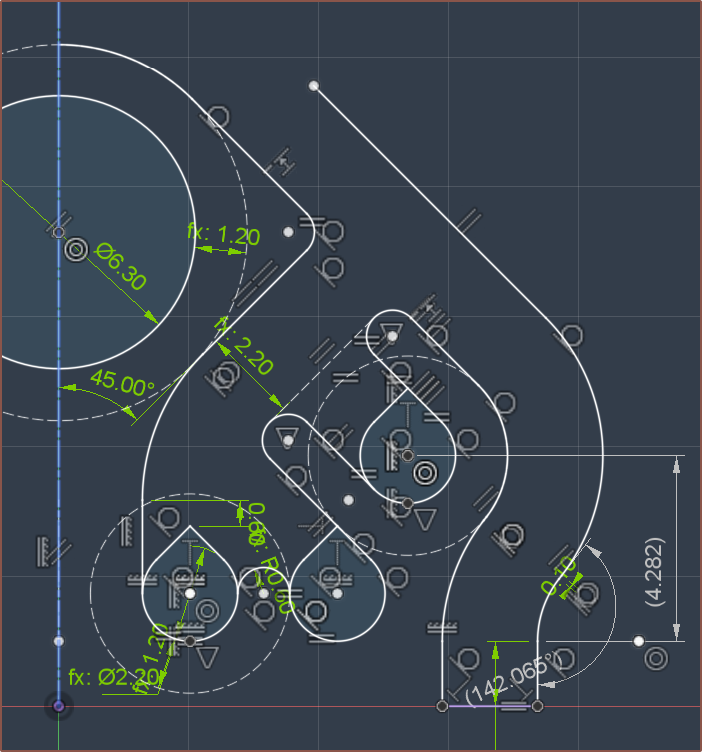 As you can see, 2 of them were very close. I decided to simulate and fine tune that part:
 Then I used the sheet metal feature to cut some geometry ideas:
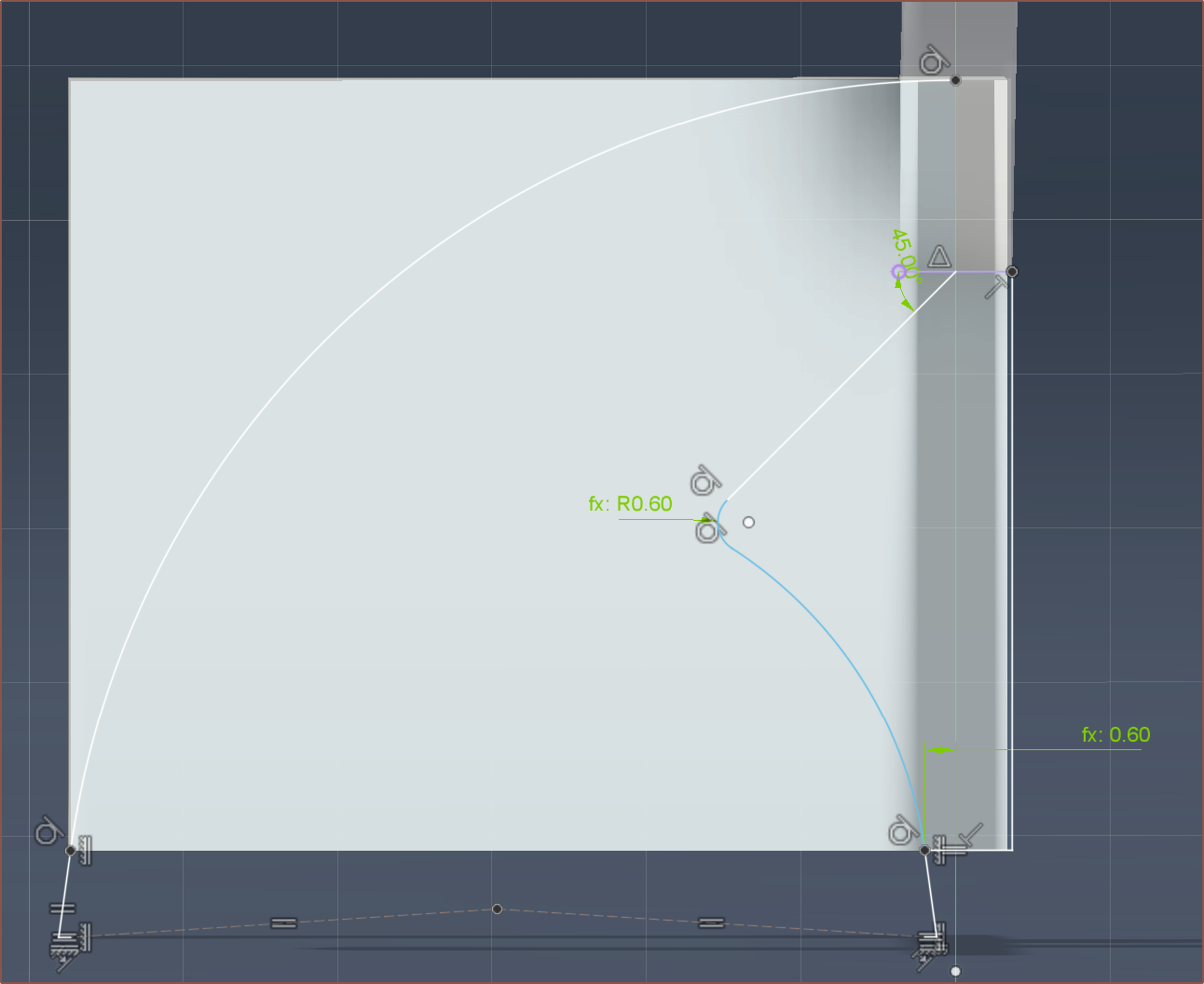 I actually decided to just have the outer curve and not the middle split since I'd need to cut out 45-degree overhangs. This is what I got:
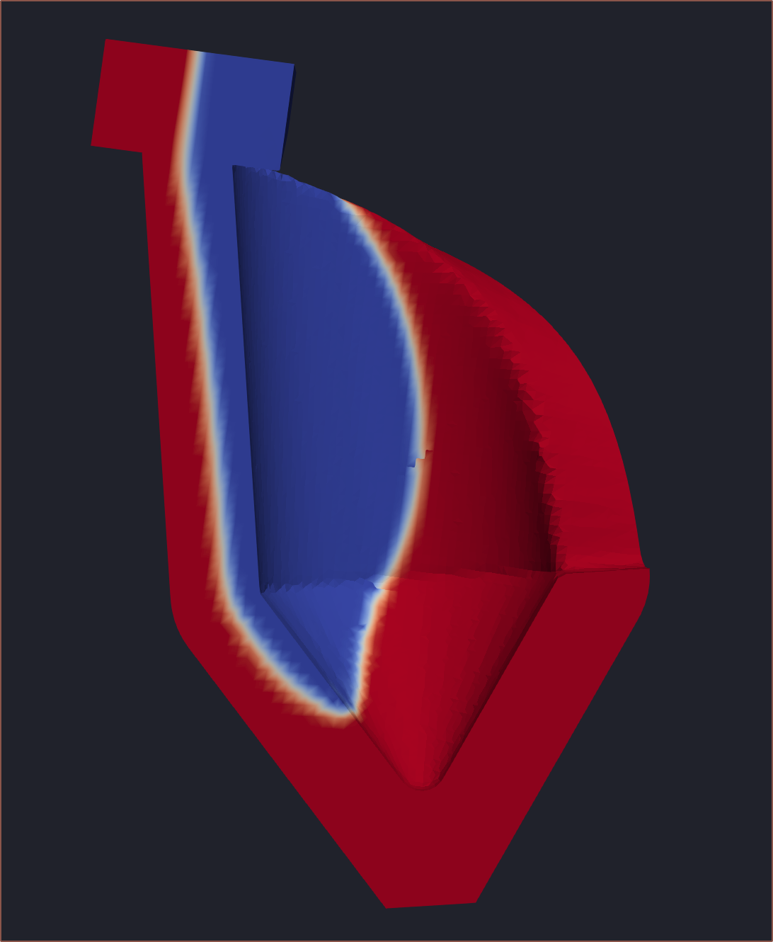
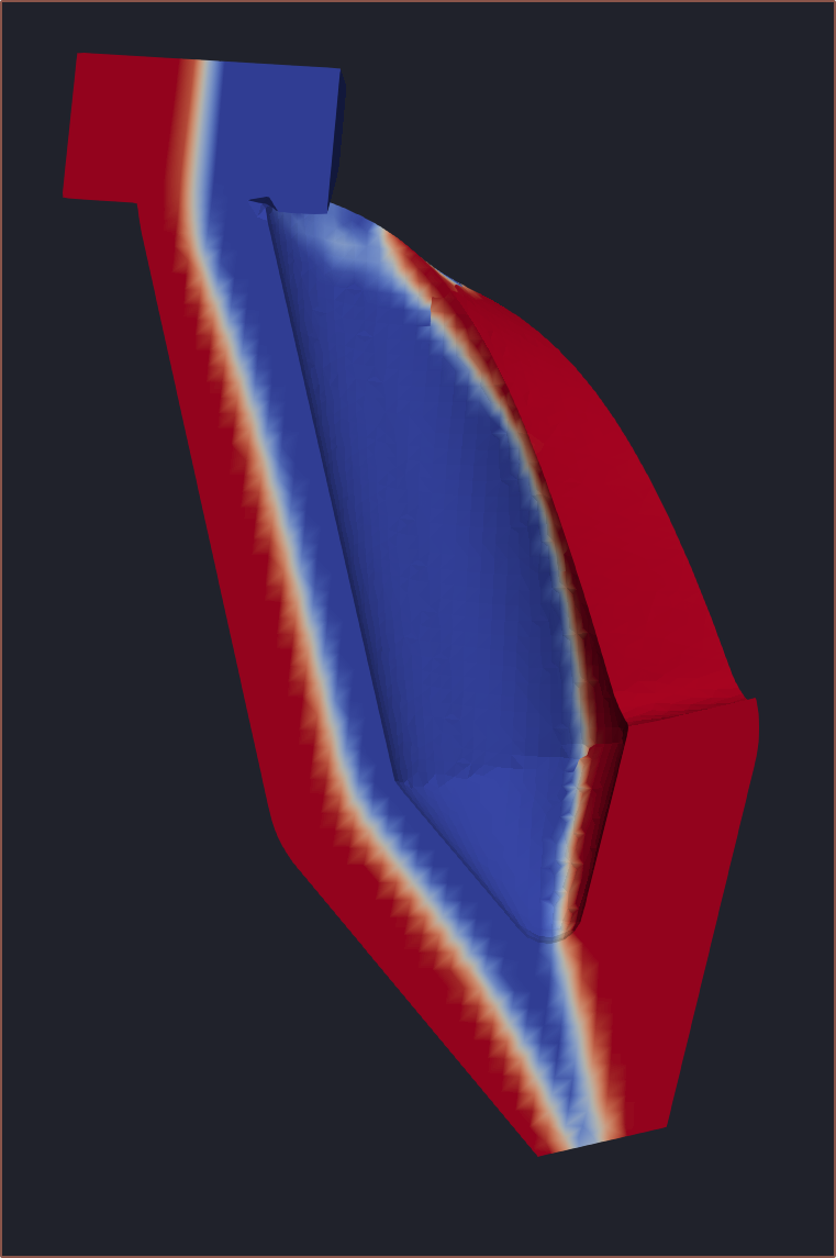
45 Degree print
I was going to struggle with those overhangs if I was to split the coaxialiser into 4. Then I had the idea to request for the entire Coaxial8or to be printed at a 45 degree angle and got to work.
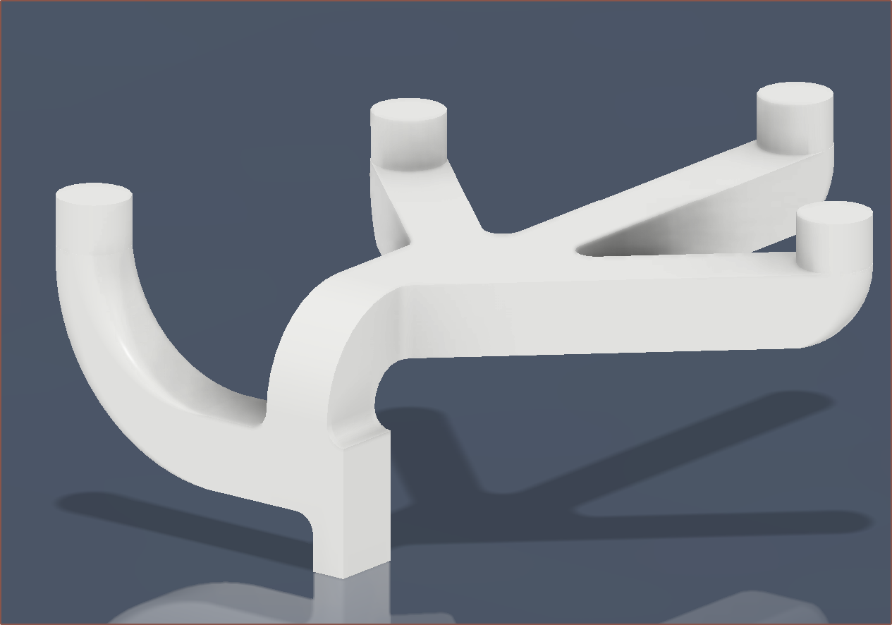
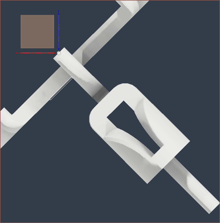
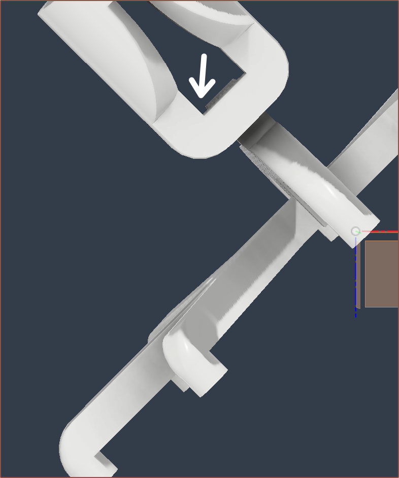
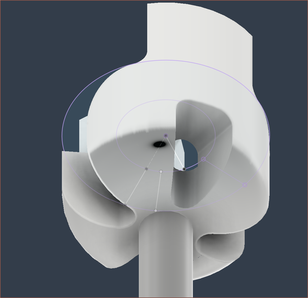
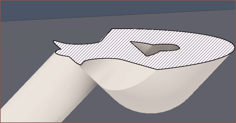


But then I had a new innovative idea, which was to use the length of the Volcano nozzle to my advantage and have a gap between the thread and the mating face so that I could fit something like a small file to polish said face:

Thus the length of the output was shortened and then I simulated it:
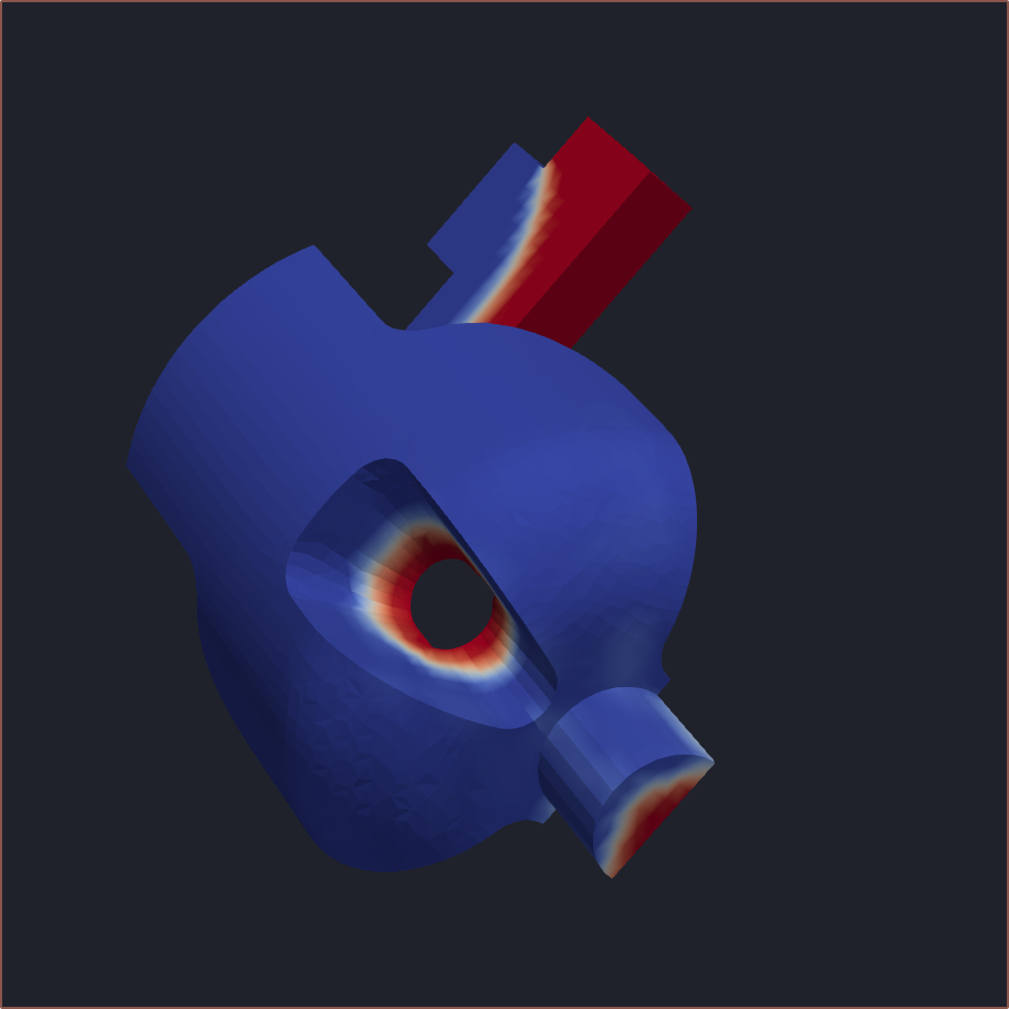
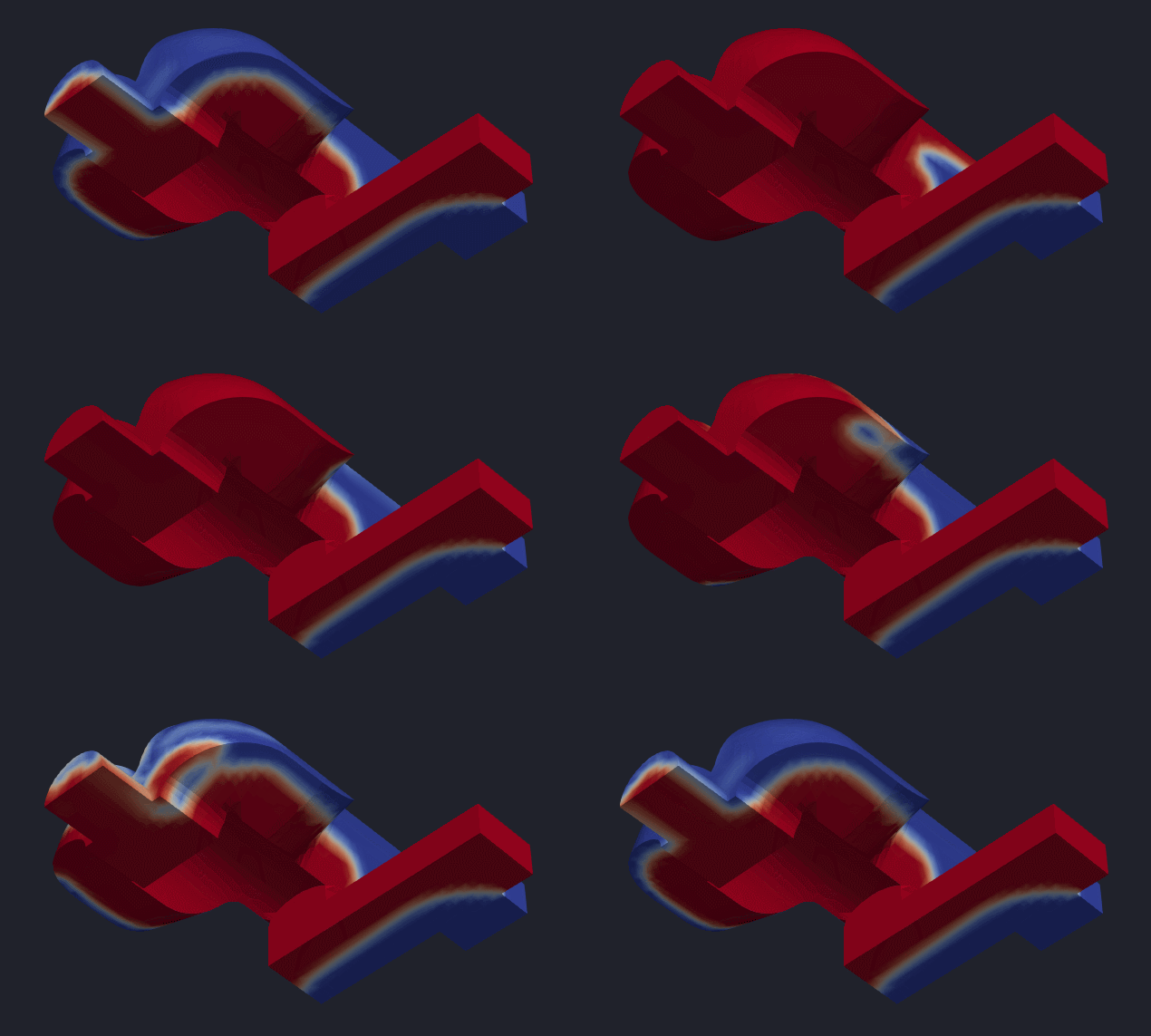
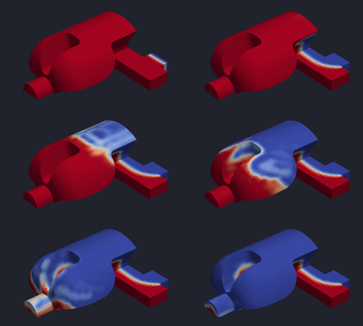
I did notice that I was getting an oval so I wanted to see what happened if I made the coaxialiser larger. It didn't seem to have much of an effect:
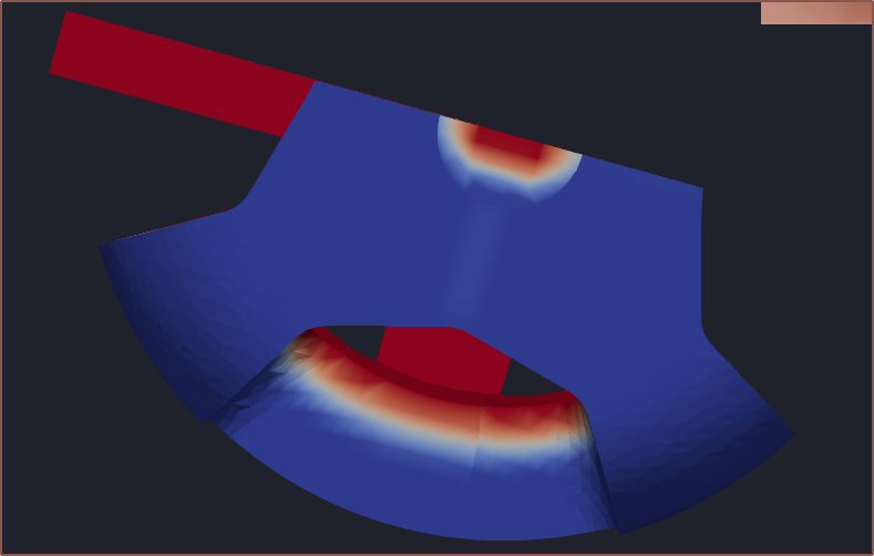
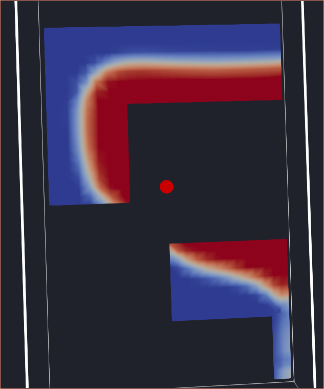 Instead, I went with a smaller version:
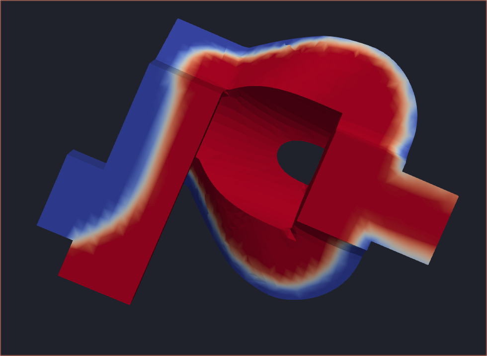
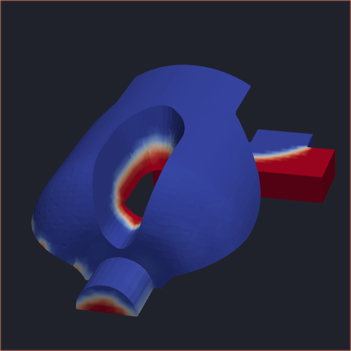 Part of the issue is that the flow doesn't actually curve around:
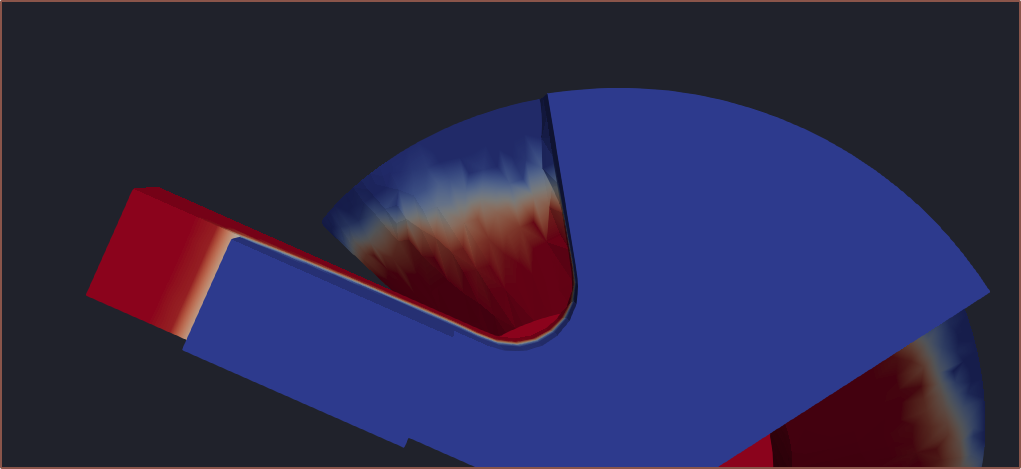
Making the outside block
Started with the placement of cutouts and then started to model and refine the look of the design:
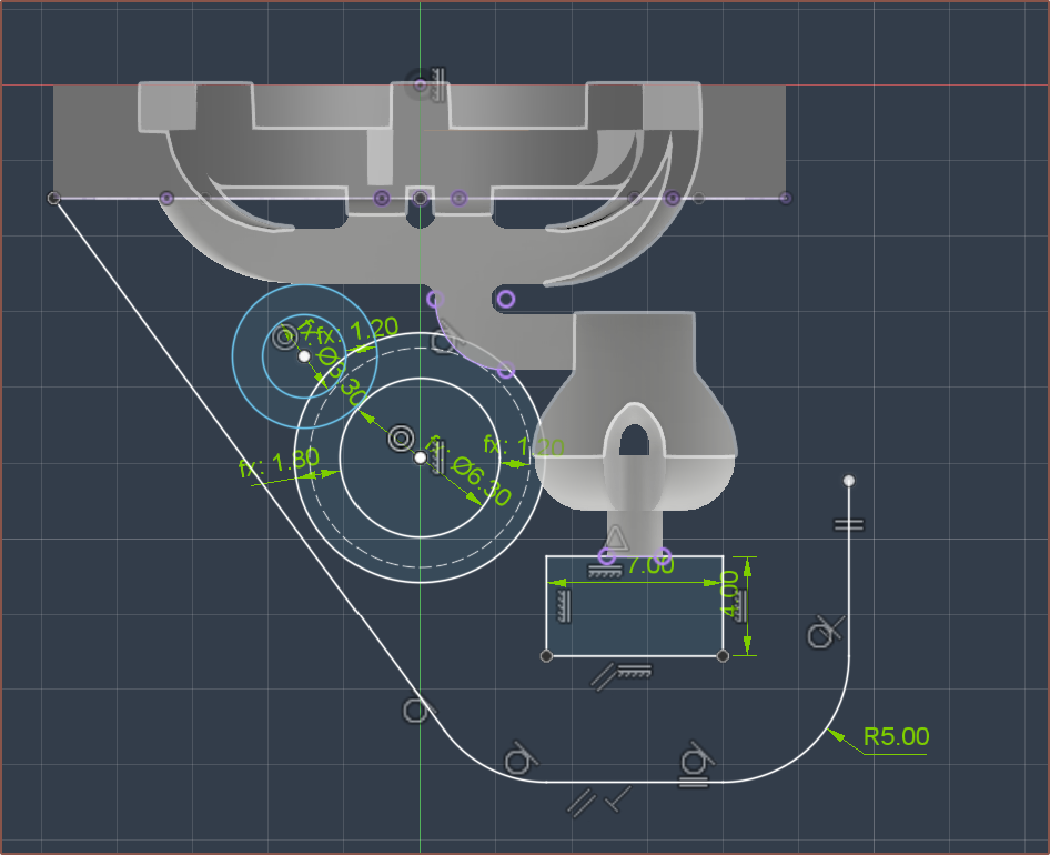
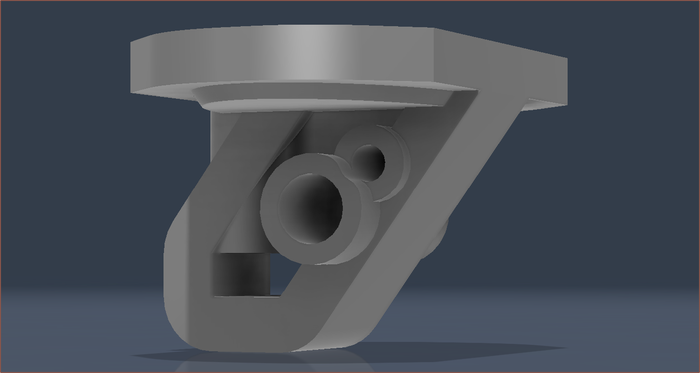 I made the thread a separate body so that I could rotate the generated threads if needed:
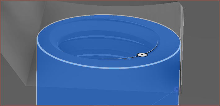
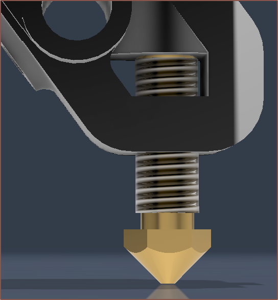
I increased the gap to 7mm and then extruded a cylinder to make up the rest of the distance:
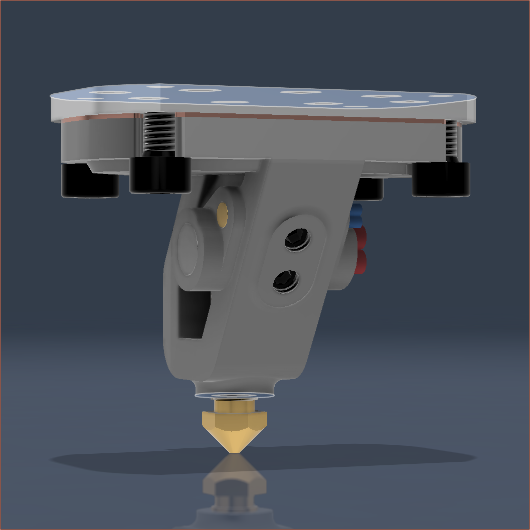
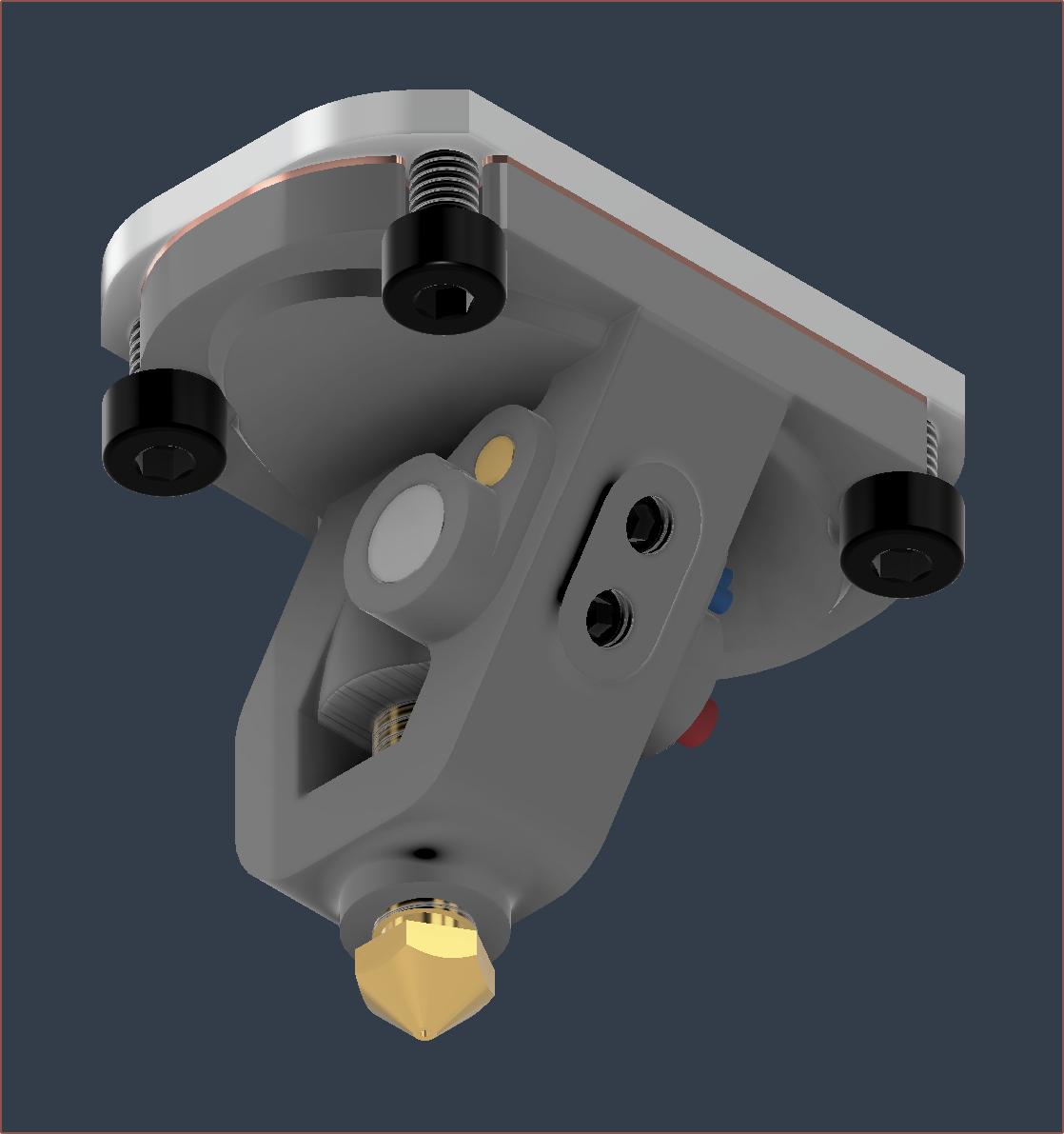
I then sent the .STEP to PCBWay who confirmed that it was printable.
Conclusions and insights
I also tried other strategies that didn't really help with the oval, but at least now I could simulate the blower idea I had a while ago.

While writing this, I've tweaked the split slightly:
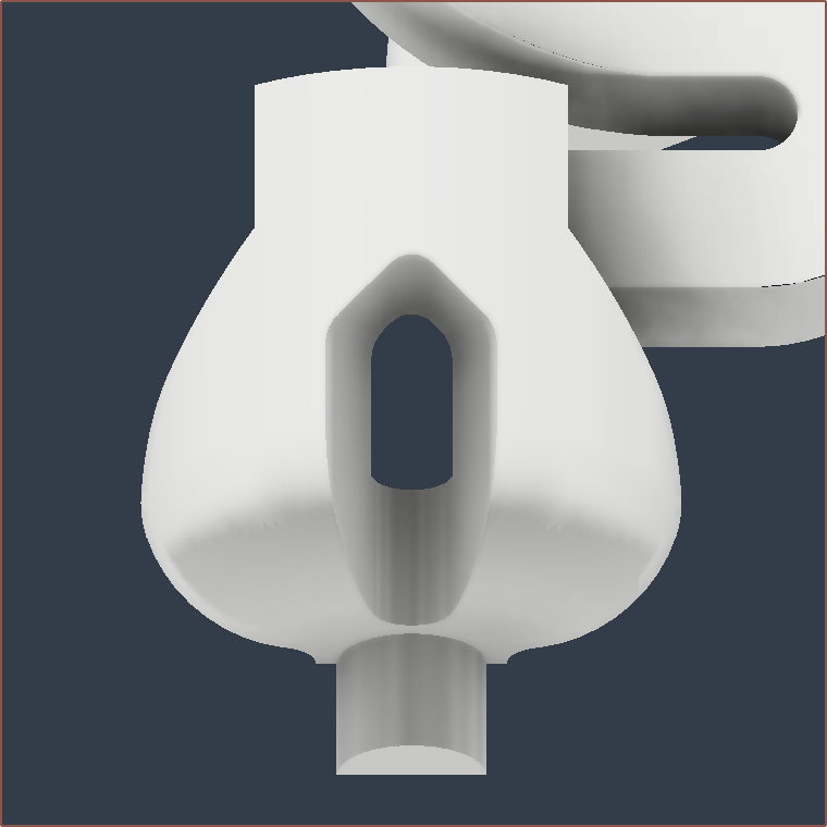
I believe that the heatblock looks even more polished than before because it's more symmetrical and there's no lumps sticking out of the clamp plate area. It's also nice that a lot of heater complexity has now been removed. It's now just like a standard hotend with 1 cartridge and 1 thermistor required.
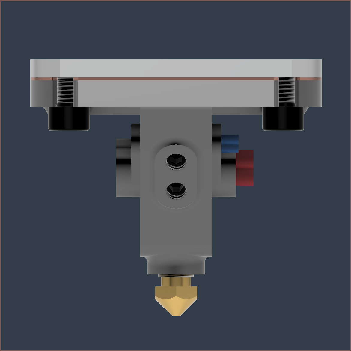
Metal volume is 11.2cm3 and the pathway cut was 0.822cm3, down from 2.2cm3 in Coaxial8or R0.
 kelvinA
Discussions
Become a Hackaday.io Member
Create an account to leave a comment. Already have an account? Log In.