This log is going to be a bit larger than I would've intended because Hackaday.io has caught a bad case of the 500's for the past week:

New heater wire
I cut the cartridge 40mm from the black/white tubing, and then stripped the wire ends by 20mm:
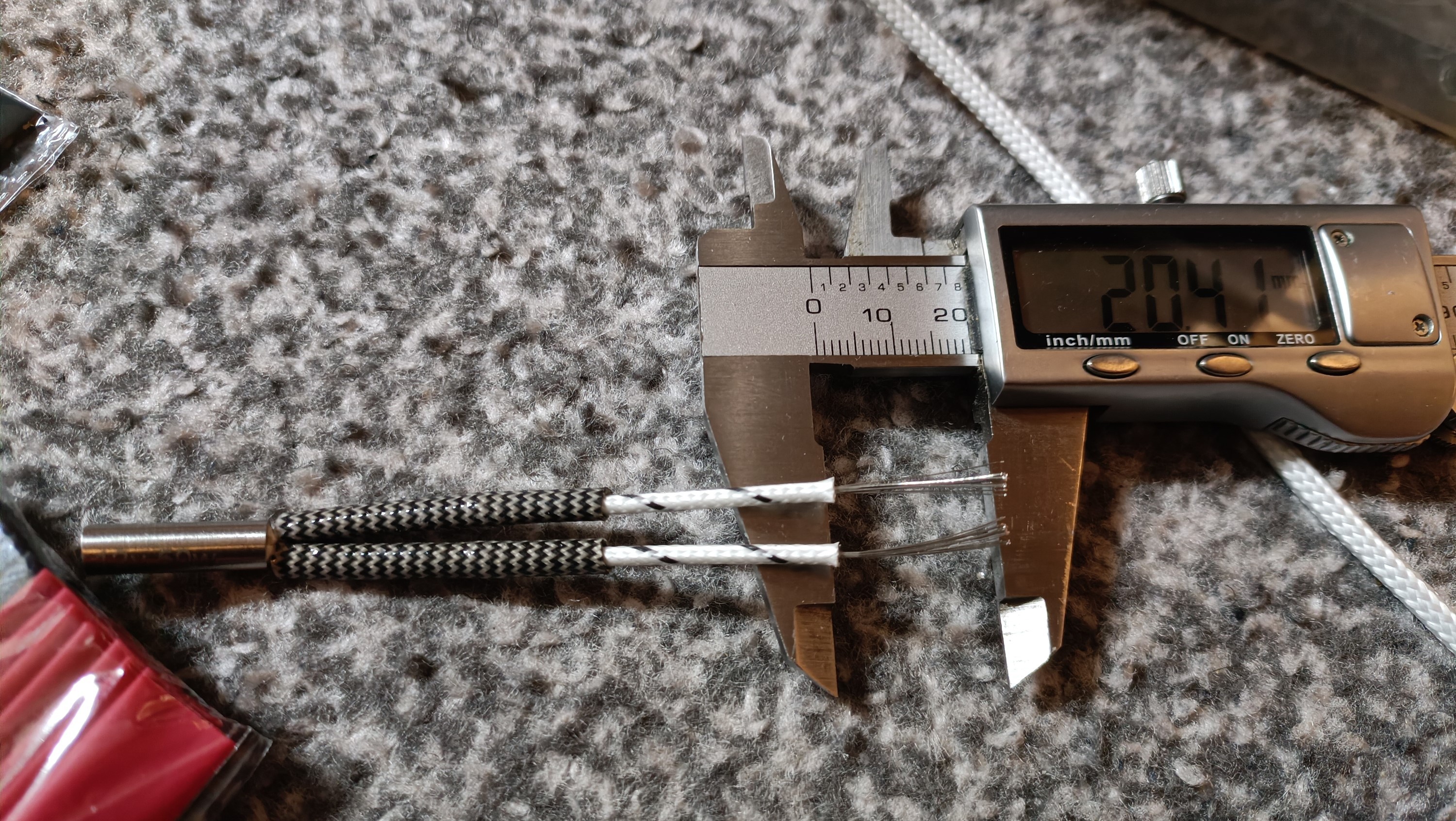
The hope is that, with the short wire length, it's sheathed with fiberglass and the fact that this wire would have air blowing over it, this wire will handle the 8A of current.
I did the same 20mm splice with the AWG15 wire and actually did the twisting right this time:
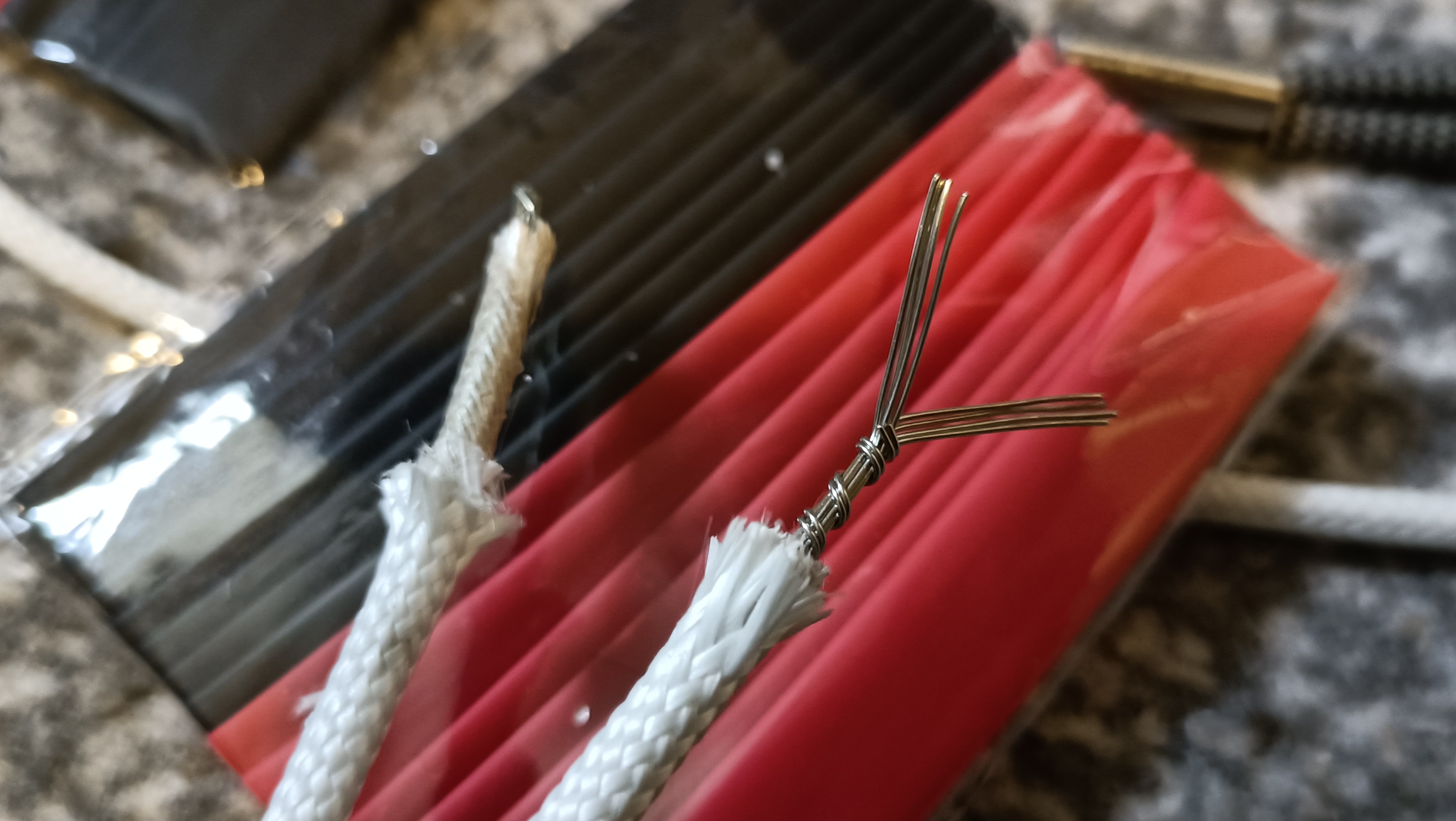
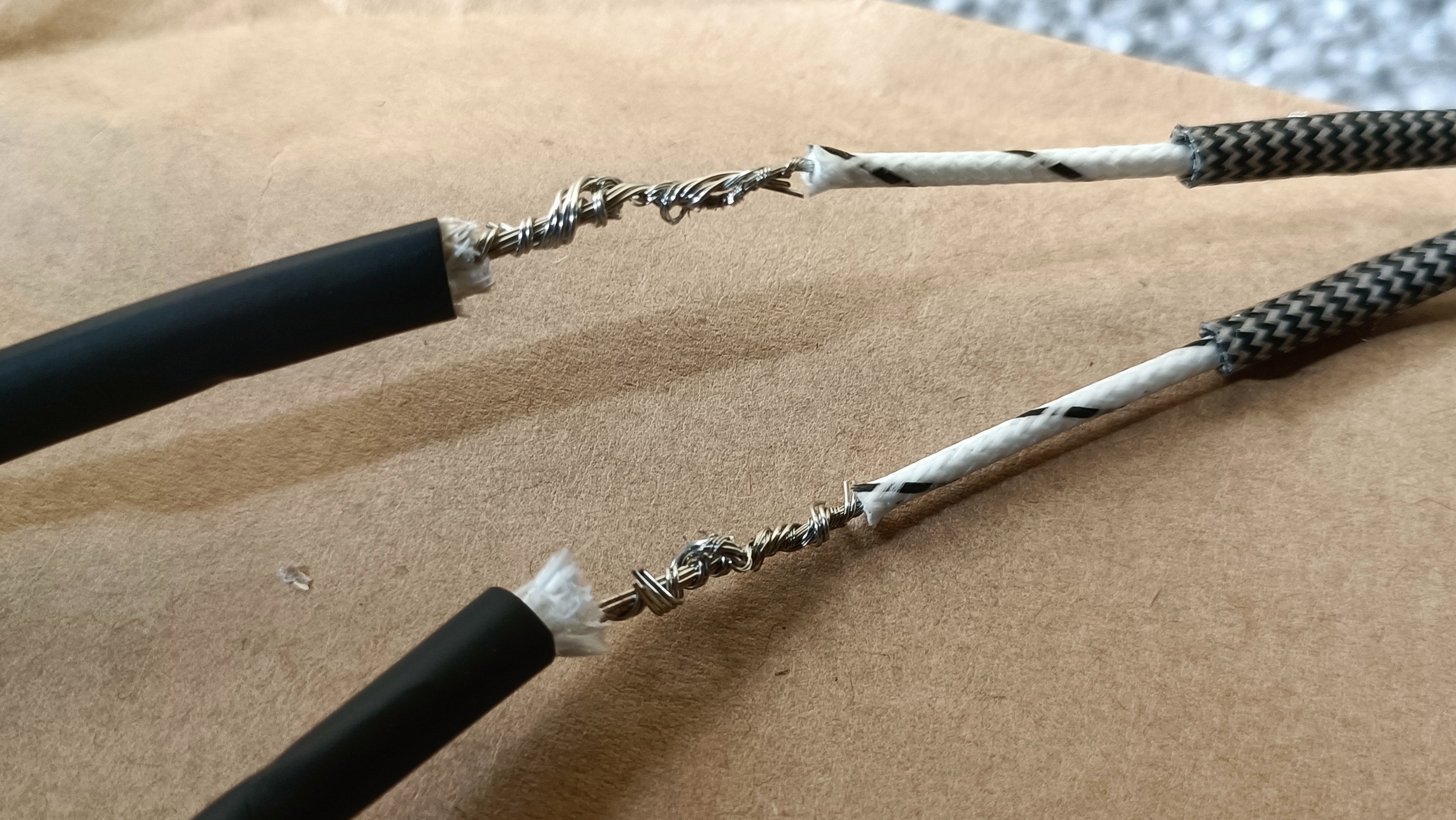
Lastly, I put what felt like copious amounts of solder (because there was just a lot needed) and then heatshrunk over:
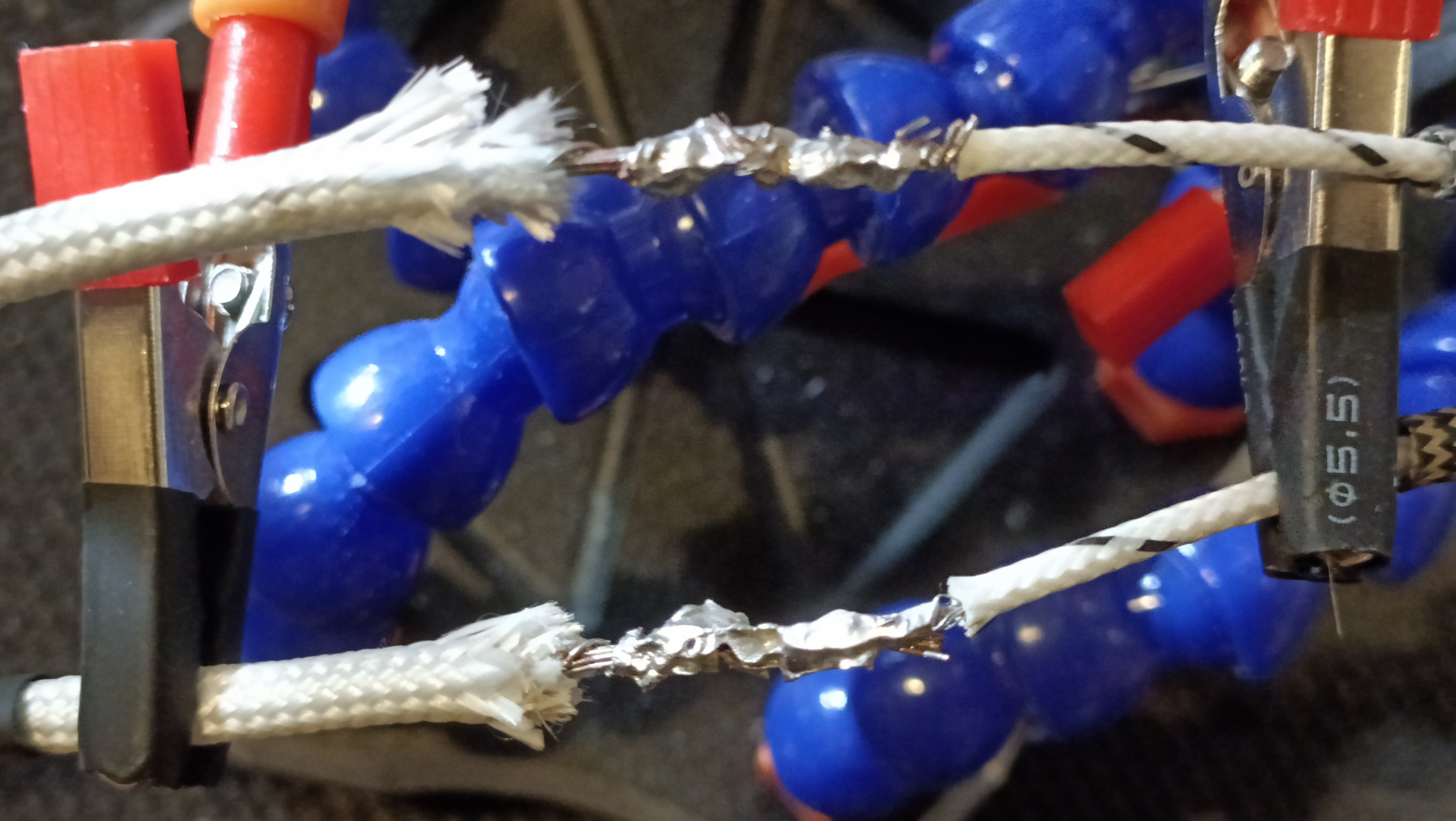
Since the outer fiberglass insulation is so thick, I used yellow ferrules and double crimped them. Next, I twisted the wires but had to leave a portion that was untwisted so that I could squeeze the wires through the extruders. Perhaps I should've twisted before doing the ferrules, because the outer fiberglass of one side has seemingly shrunk:
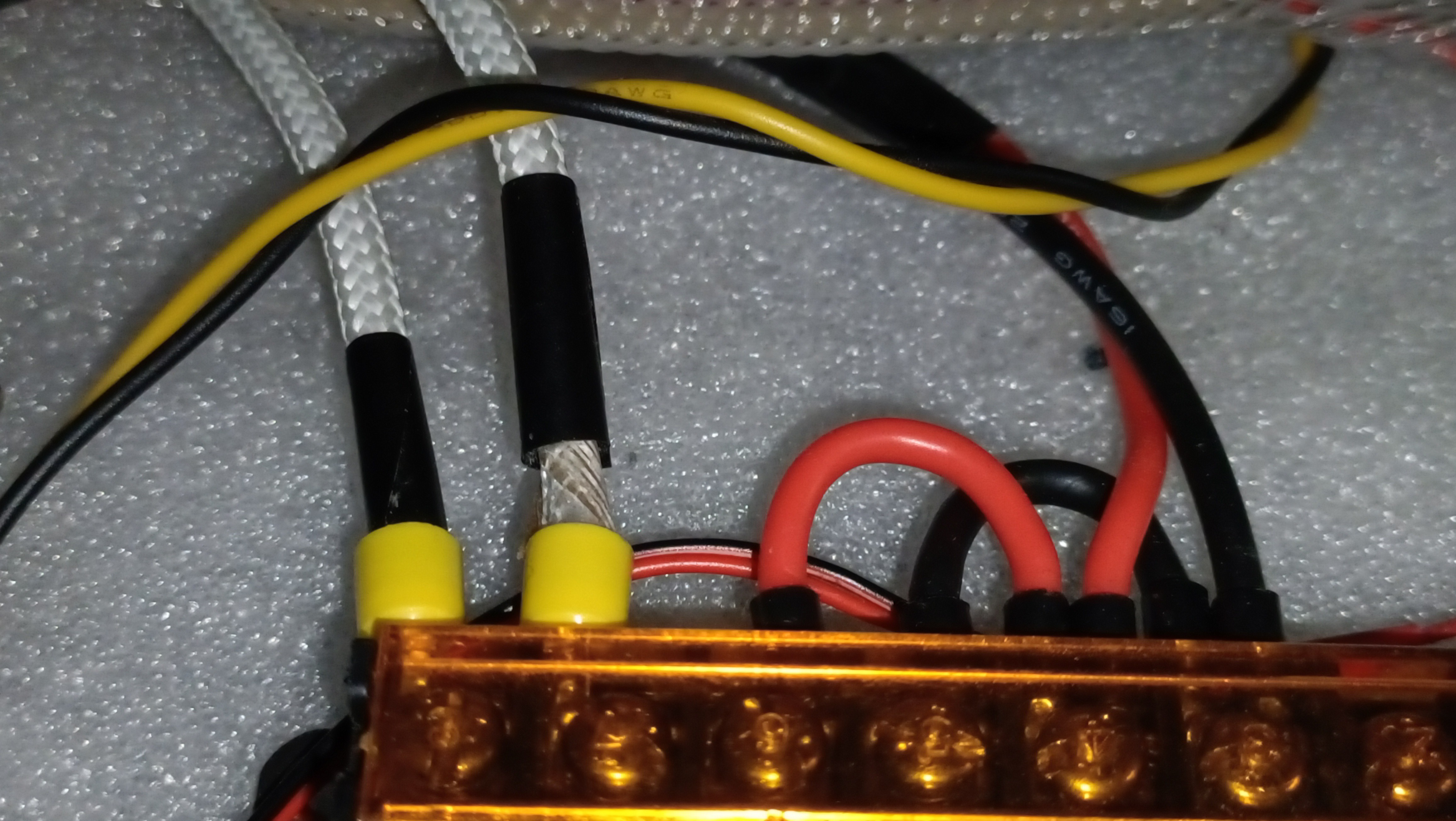
It's fine though because there's still mica and another layer of fiberglass before the conductors. It's just not as confidence-inspiring to look at.
Temperature calibration
Powered on the printer and the hotbed was reading -4. Decided to ignore that and run MPC autotune. I was able to get an initial reading before Repetier Host ghost-disconnected. (I still haven't tracked down why I'm getting this issue.)
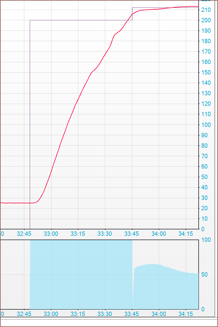
At least it was enough to see 2 things: I'm still getting the same divot in the same 150C area, and the heater power at temperature is 50%. The latter means that I perfectly estimated that I'd need a 200W cartridge and the former likely meant that it was the thermistor table at fault.
I changed both thermistors back to the ol' reliable "1" in Marlin and now the reading was smooth, but I also had to retune MPC:
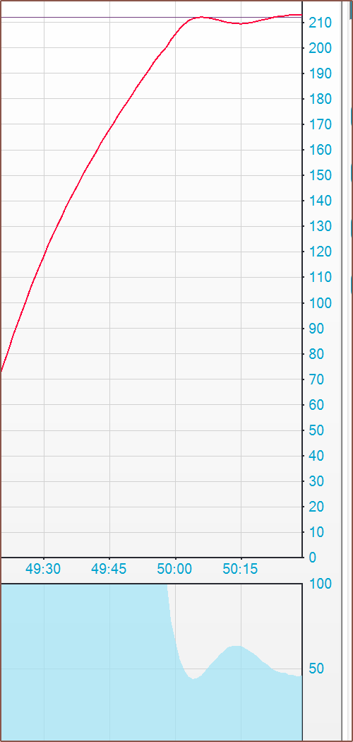
The new MPC tune gave a heat capacity of 40.73, up from 9.55 when I calibrated the CHC Pro. It's not directly comparable since the power put into the CHC is temperature-dependent, but it's a tad over 4x which is in the ballpark of the volume differences between it and the Coaxial8or.
The next day, I fixed the bed thermistor crimp. The wire was fine so it meant that there just wasn't enough of it to crimp strongly, thus I doubled the stripped length and folded it on itself before recrimping.
Extruder order
I also decided to swap the extruder order while putting the bowdens back. Now Ch1 is the outermost filament. I then loaded the material I had on hand.
It was only after putting in TPU last that I realised why Me In The Past decided to have Ch8 be where it was (as well as limited wire length). However, it would be a good order if I wanted a TPU core like that one CNC Kitchen video. Thus, it's a bit like a PCB stackup in that, for a 4 layer board in Fusion for example, layers 1, 2, 15 and 16 are important.
For the Coaxial8or, it's 1, 2, 7 and 8. Therefore, I'm considering switching the extruder wiring so that E0, E1, E6 and E7 are the four extruders with the shortest bowdens, and in a clockwise up-down-down-up fashion (see doodle below) instead of the up-down-up-down configuration currently. For now though, I've just left them since I'd have to take out the bowdens and put them back in and these pneumatic fittings aren't ideal.
#define INVERT_E0_DIR false
#define INVERT_E3_DIR false
#define INVERT_E4_DIR false
#define INVERT_E7_DIR false
#define INVERT_E1_DIR true
#define INVERT_E2_DIR true
#define INVERT_E5_DIR true
#define INVERT_E6_DIR true
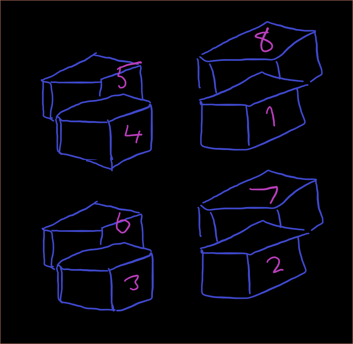
With this, 1 and 8 are on the top, which is both easier to see and access than the bottom. Additionally, the middle-of-the-pack ch4/5 are also easily accessible. Thus, this configuration acts somewhat similarly to if there were only 4 channels in the same clockwise fashion.
Material and Prusaslicer setup
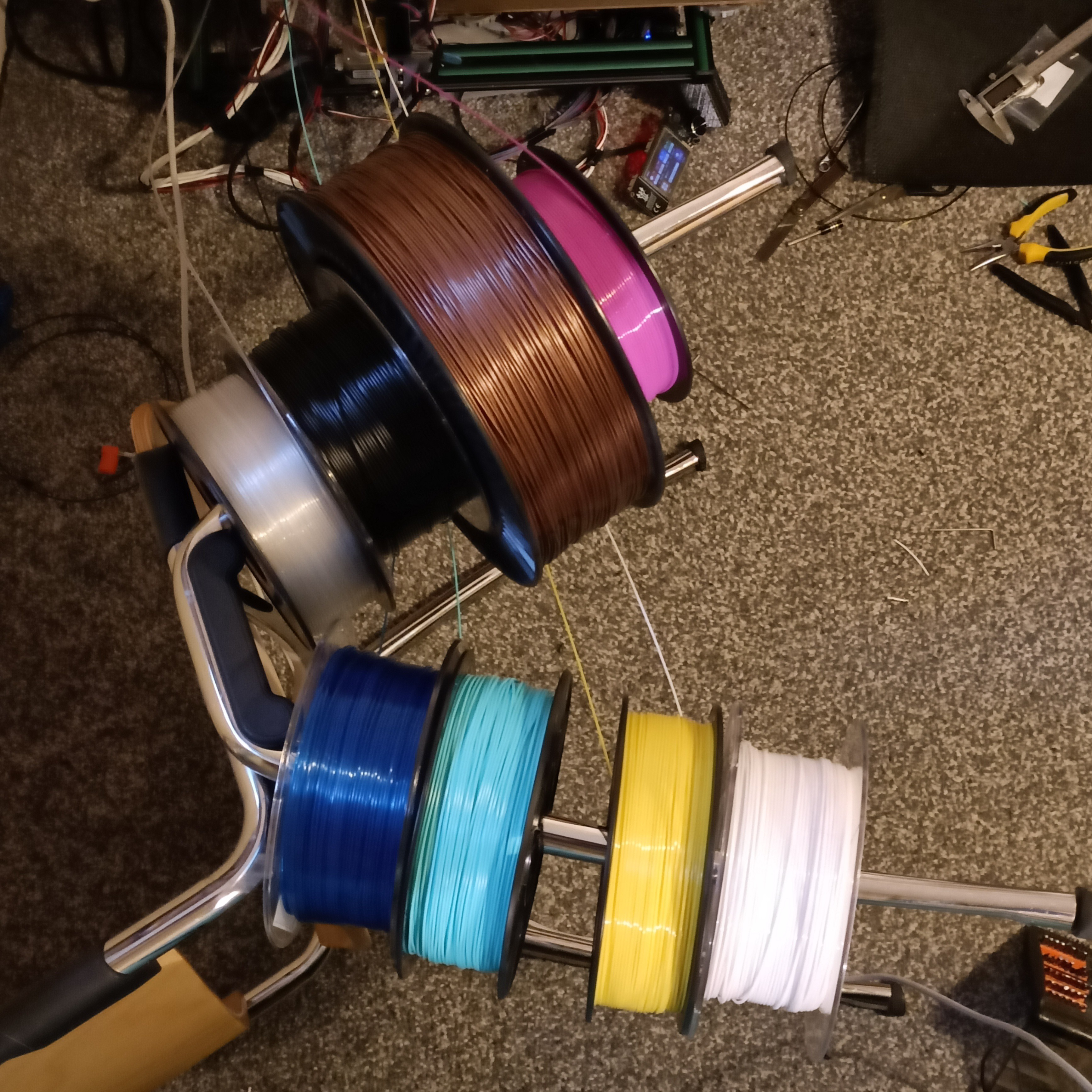
Instead of leaving the spools on the floor, I had the idea to use the legs of a chair as filament holders and it worked nicely:
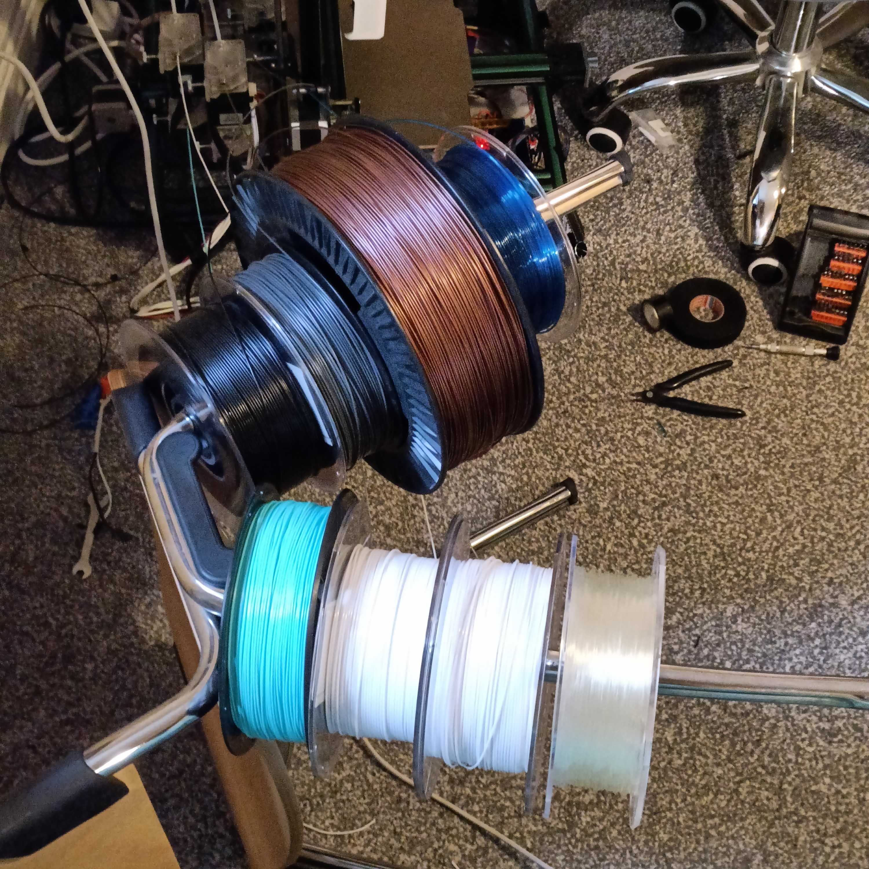
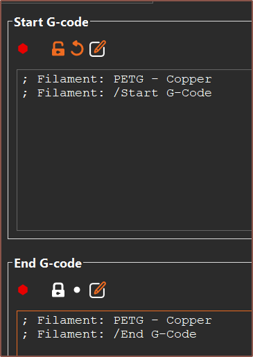
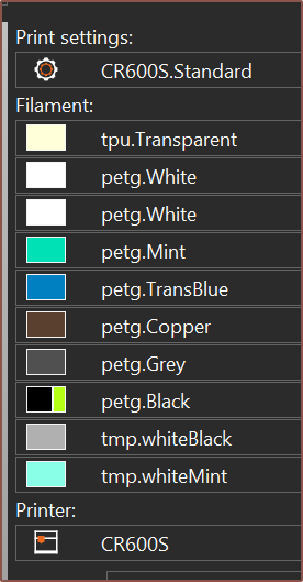
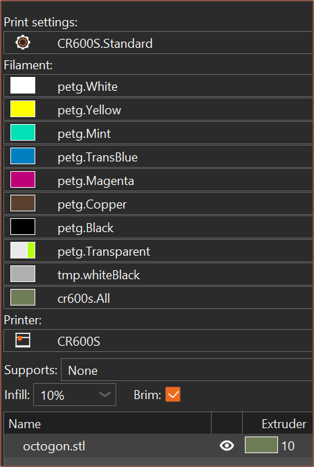
I then added these into PrusaSlicer. I also added the name of the filament in its start gcode to potentially aid in diagnostics. I tried to use macros but couldn't get them to work.

First test print
The next day (on the 21st of September), the rest of the filament came in so I swapped one of the white rolls for yellow so that every input is unique. Worst case scenario is that I at least know what channel leaked.
This first test print is a simple octogon in pure white just so that the hotend can get filled with material and I can see if the nozzle is high enough from the bed.
Filament started coming out. It started as black but then changed to white, which could be due to the black filament or residue powder. Filament seemed to be pressed yet peeling off the bed. I measured it to be 0.3mm when it should be 0.5. Soon I got extruder skips and decided to cancel the print because:
- Filament indeed is coming out!
- My bed indeed is too close for some reason.
- Skipping steps means there's no leaks, right?
Reality:
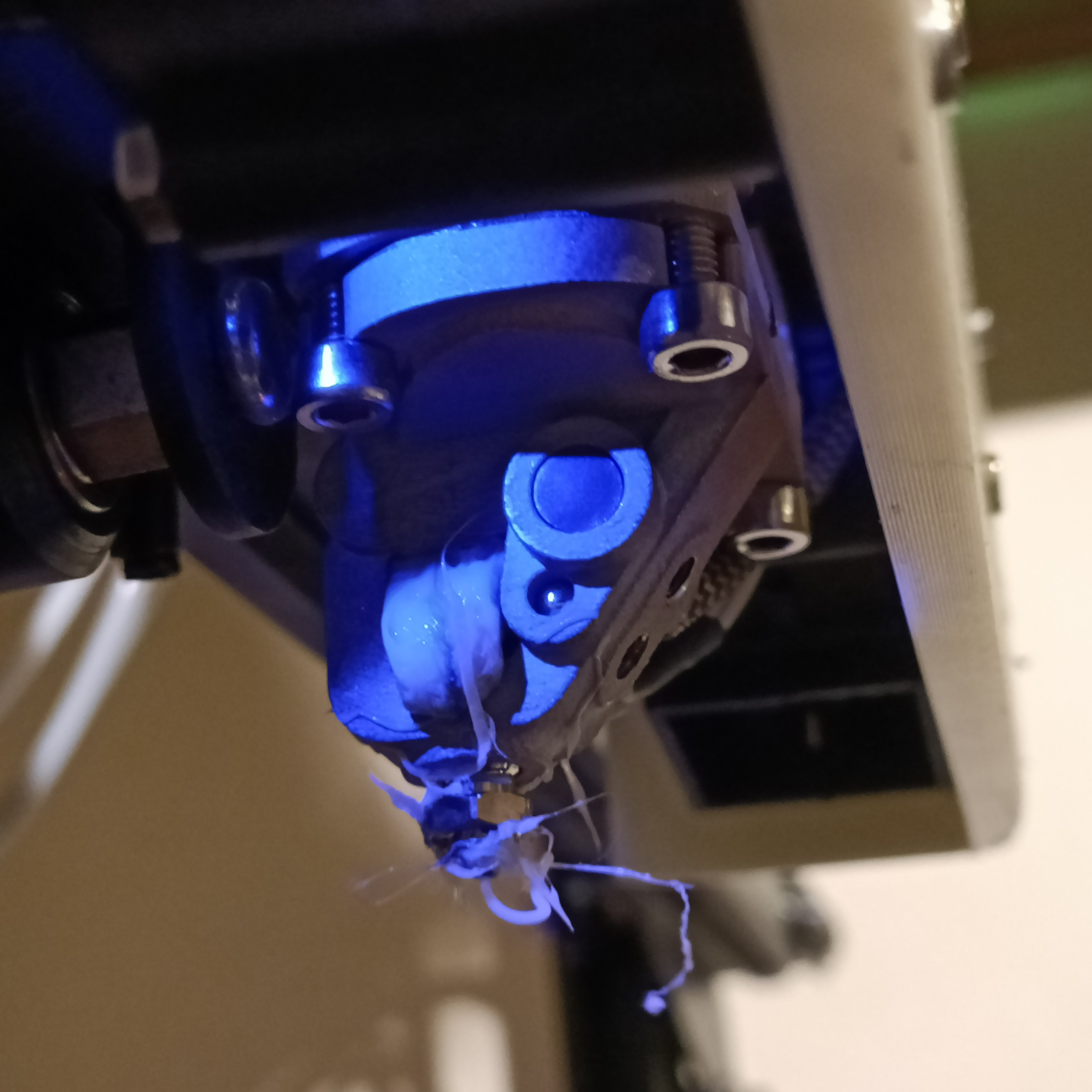 Me who just spent £50 on new material when even the basics aren't going right:

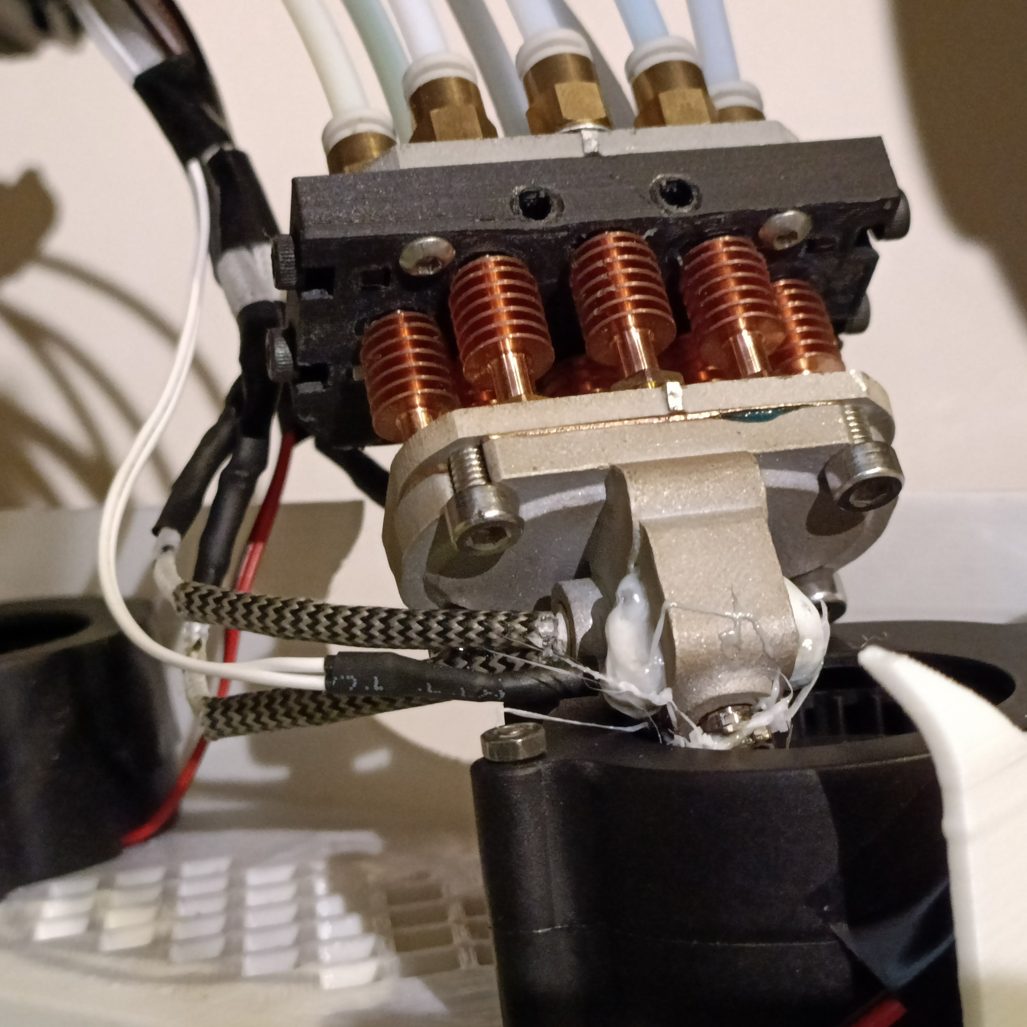
Well I got the idea to cool down, flip the cover around, heat to 100C and then start pulling things off.
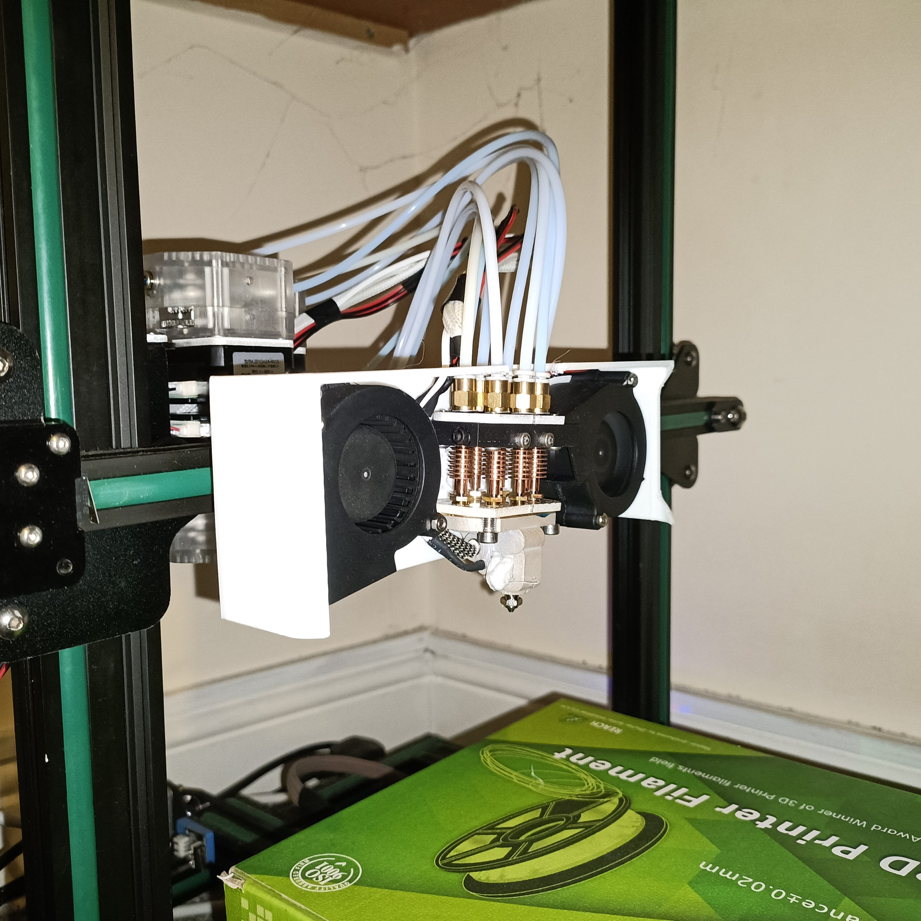
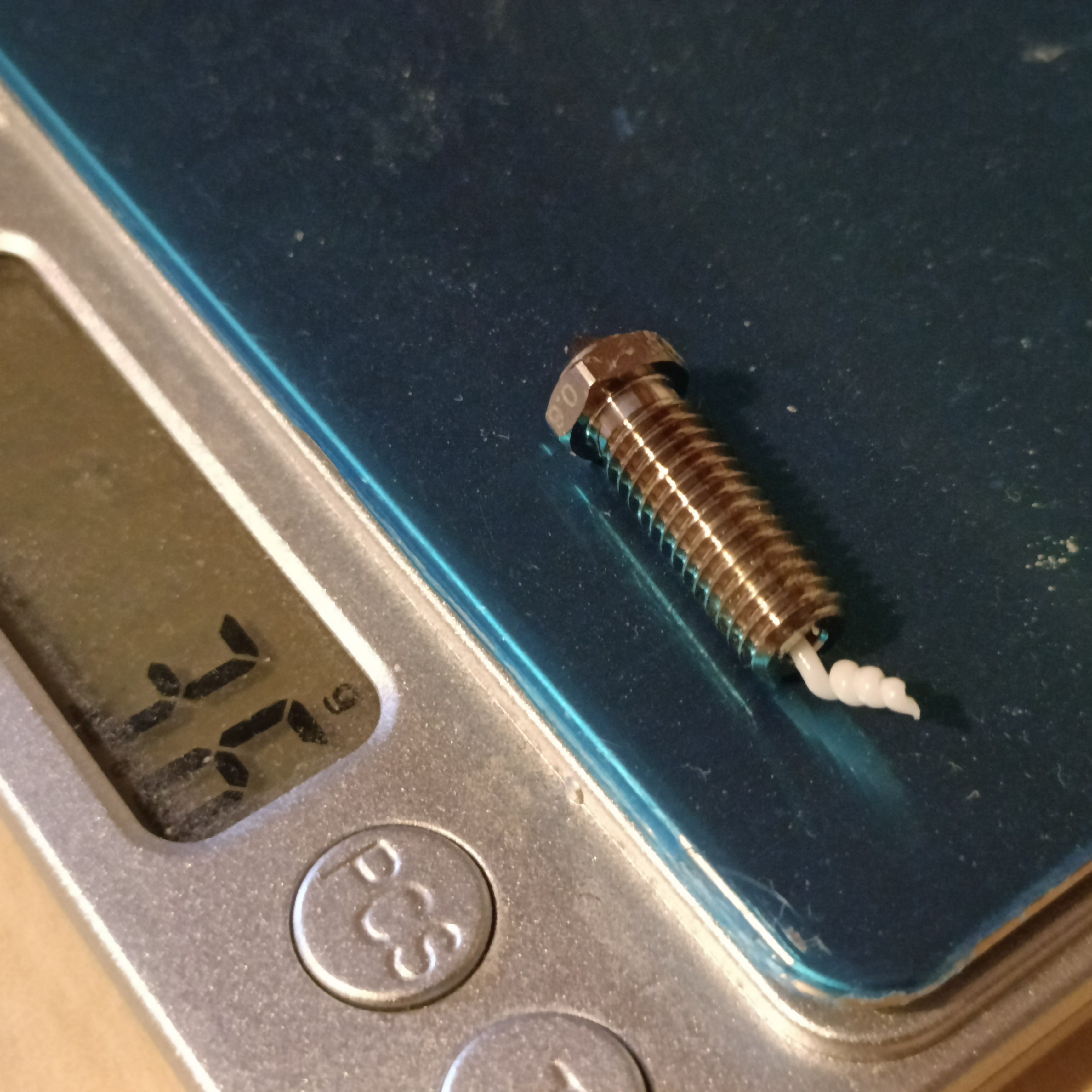
The PETG whisps pulled cleanly off the hotend and the outer parts of the c8or. I then turned the nozzle and felt no resistance, so I presume that thermal expansion meant that it was unseated. The nozzle is nice and clean:
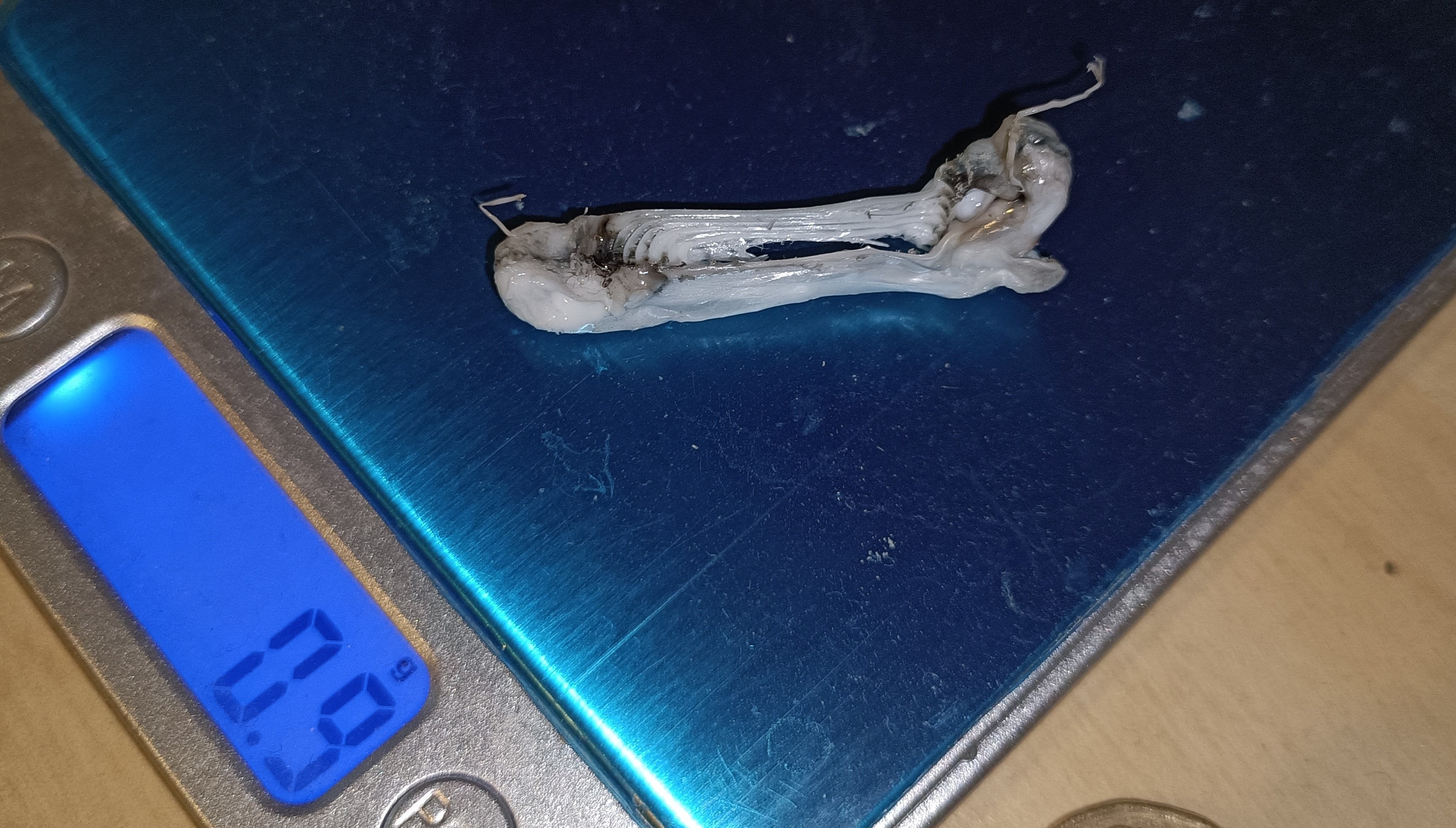
The blob was then able to come out with no residue left on the c8or:
Heater cartridge failed
Had lunch, then heated the c8or to 250C to tighten things at temperature, such as the apparently-leaky Channel-5. Next thing I know, I've got a kill() message on the touchscreen and see that my temp is sub-200 degrees. I command a reheat but there's no power being taken from the PSU and the temperature is still falling, so I wait for a cooldown and get a measurement.
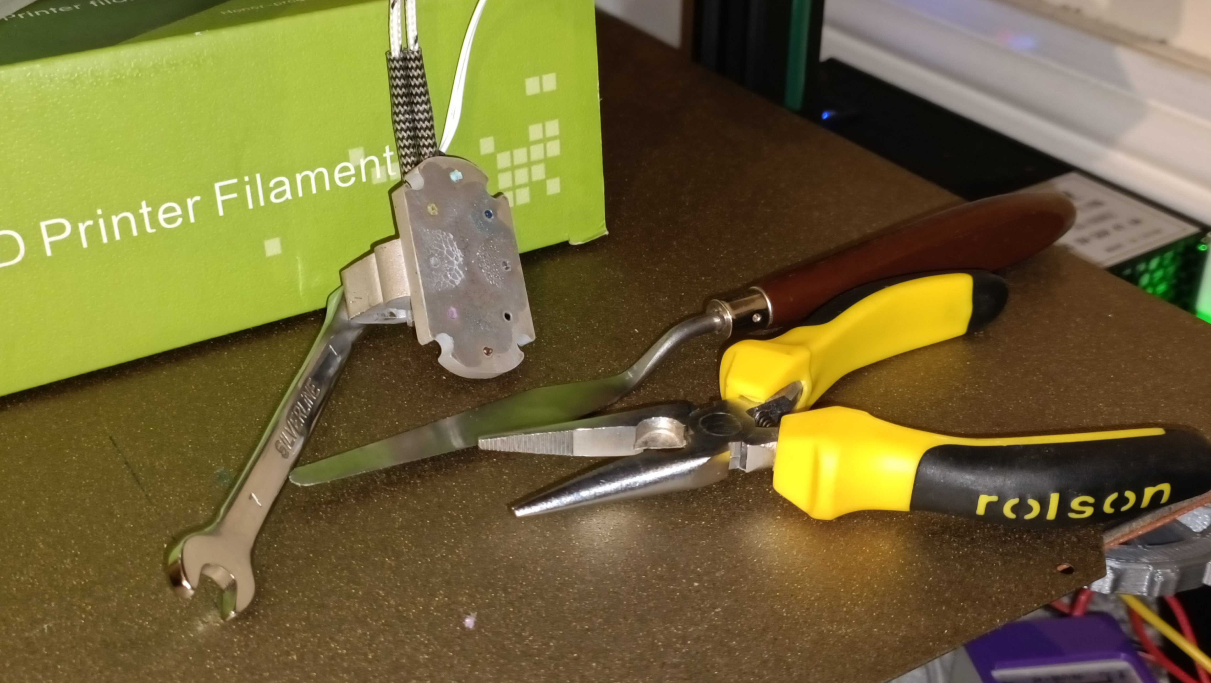
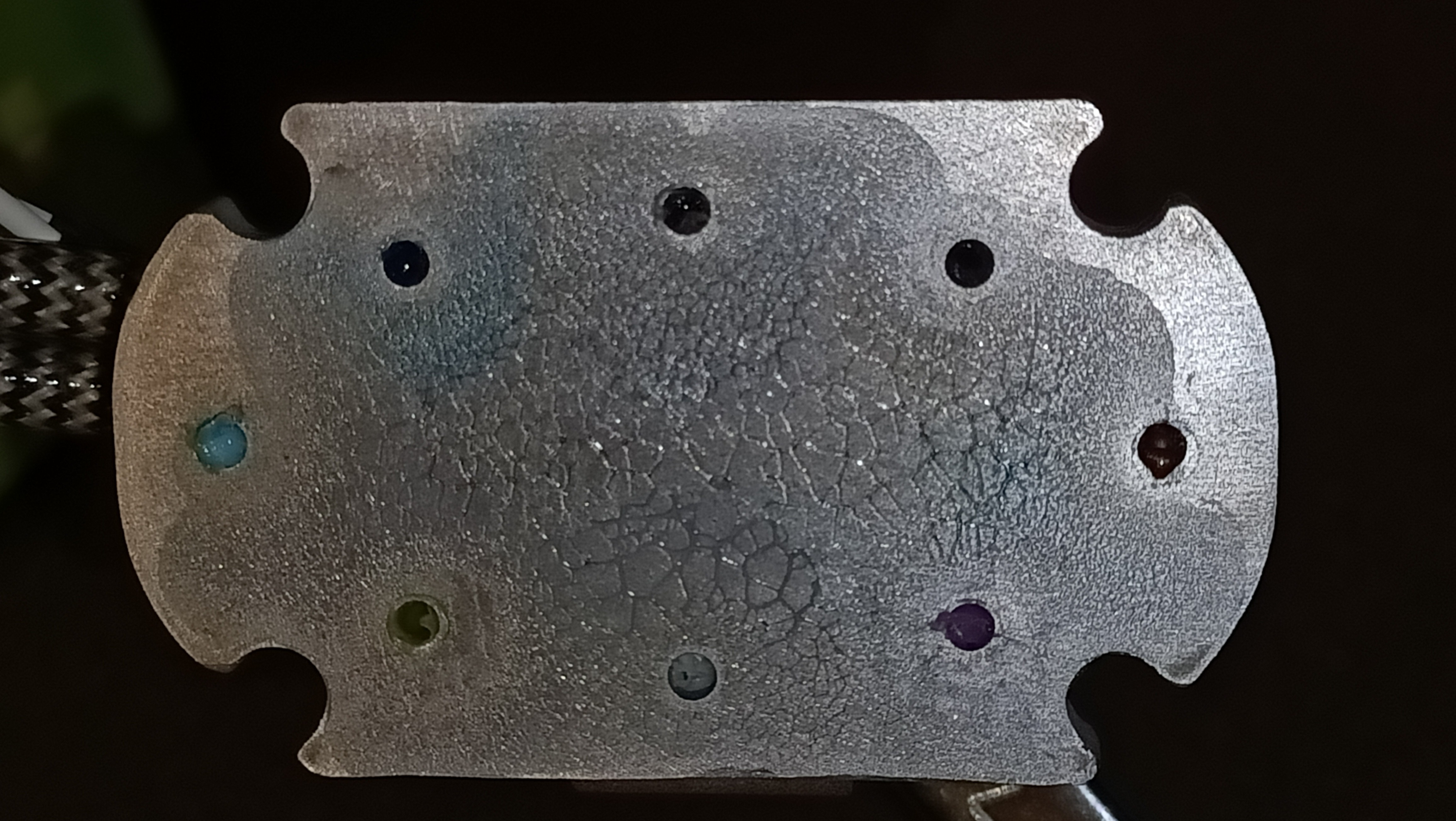
Next morning, I had measured it to be an expectable 2.9 Ohms. Now, it's 4000 Ohms across the PCB terminal blocks, which is just from the PCB itself. The actual resistance of the cartridge is now at least 0.3 megaohms. I have worried that the airgap could be an issue, since I never expected to need to put 200W into this hotend. It's very easy to visually see which side was connected to the walls and which side was held by the grub screw:
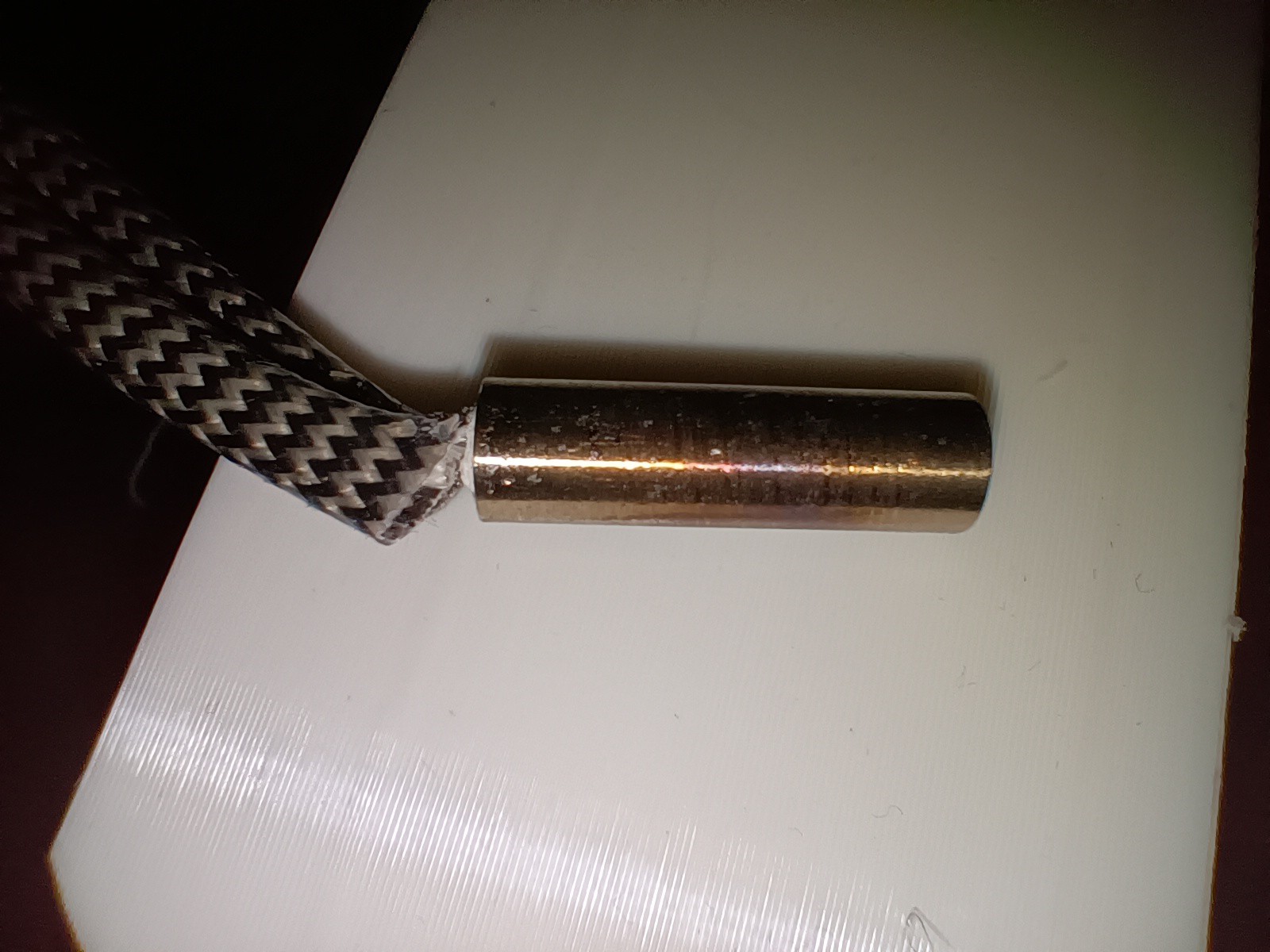

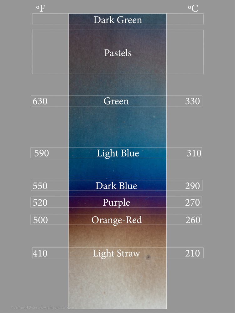
Looking at the following steel chart, it seems that the surface peaked at over 300C, with some of the thermal energy being conducted through the grub screw.
I assume that a thermal interface compound might be needed to conduct better than the air gap.
It might be possible to design R3 to clamp around like a volcano hotend (see below) but I'm not sure on if the c8or will flex correctly. Due to the lack of space, the clamp might have to compress both the cartridge and thermistor at the same time.
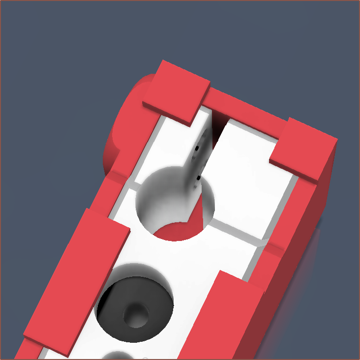 For now, I will see how long a new cartridge lasts before making conclusions.
Connectors
On the next day, since the cartridge longevity has now come into question, I stripped off a bit of cartridge wire and installed it into a lever connector to see if it clamps securely, which it does. Thus, I cut 80mm of length of a new cartridge and installed it into 2 lever connectors taped together:
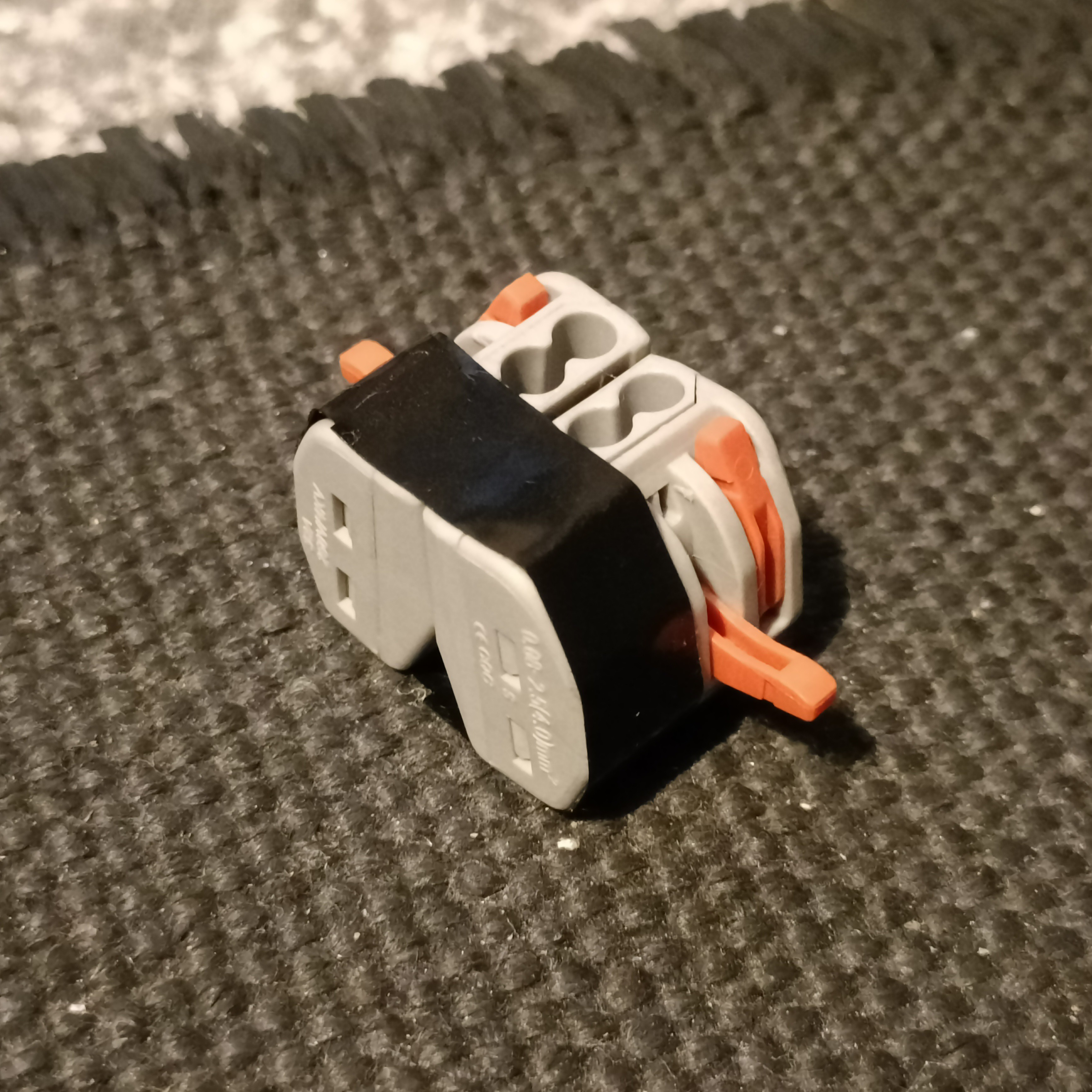
80mm is a bit short, but it should be fine for the ideal connector I could order:

On the other hand, after putting everything back together again, 80mm might actually be perfect since it helped keep the other wires neat. The new cartridge is 3.3 ohms, corresponding to 175W.
Speaking of connectors, I was able to find another M6 PTFE connector that looks nice and has a hexagonal hole so an allen key can be used to tighten it. I'm hoping that these are easier to connect/disconnect than the ones I have now.

As somewhat expected, the current connectors is easily the reason behind a lot of tediousness currently.
Thoughts on fans
Considering there is so many wires and tubes already, I'm considering ducting the airflow through tubes, though I know from #TrueTent TempLab [gd0143] that it will reduce the airflow.
I'm also considering putting both fans on the right side of the hotend to further 2-dimensionalise it.
While trying to load filament, Ch3 had the most material in it by far. It's also the one furthest away from the fans. I've taped over the grill to make sure I'm not losing air pressure prematurely.
Next attempt at the octagon
I flashed the new extruder locations after moving the cables around, as well as tightened the heatbreaks and nozzle:

Decided that I want to focus on the main use case: 6 spools into 600 virtual filaments.
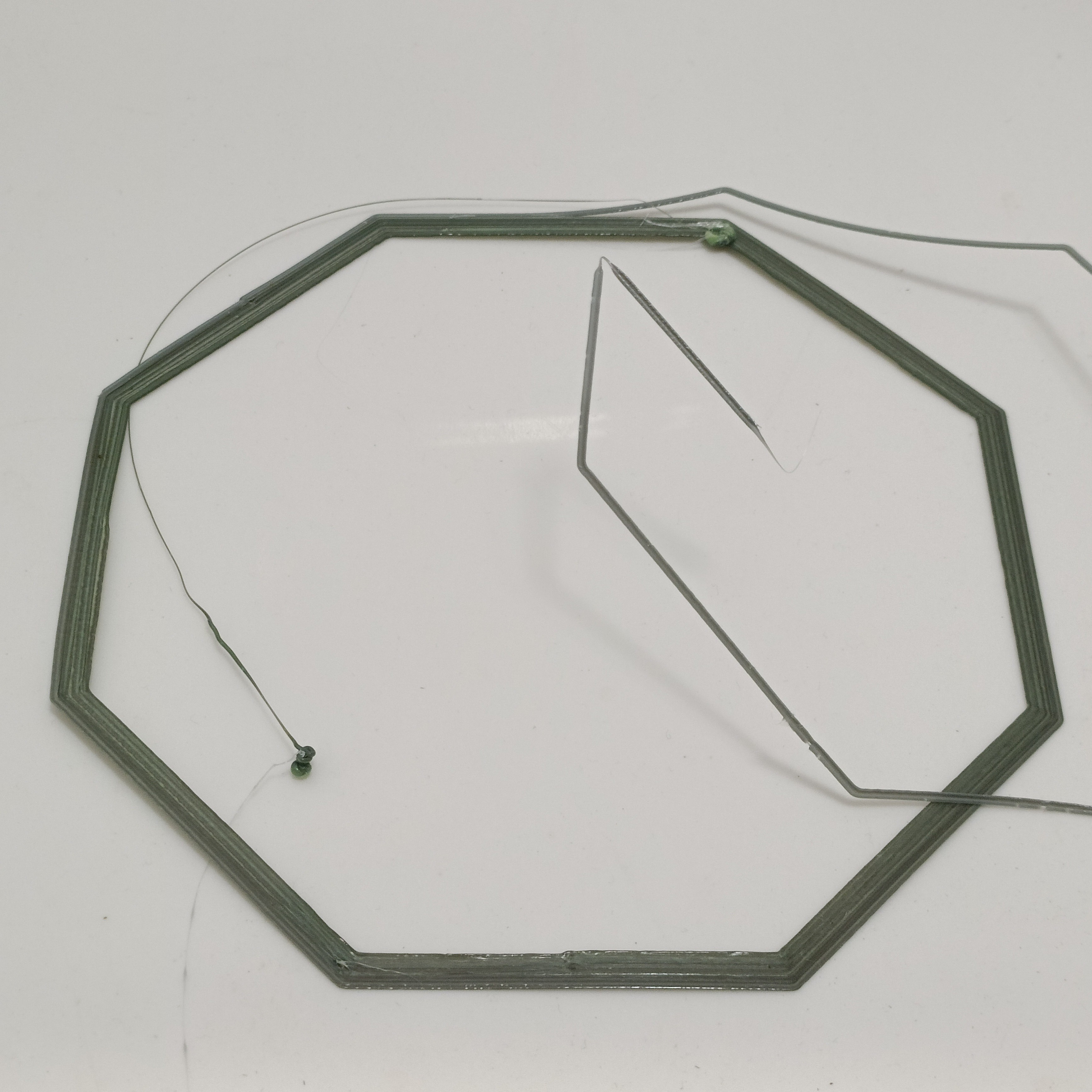
I only got 5 minutes into the print before I decided to cancel. Material wasn't sticking to the bed, and its temperature felt colder than I'd expect for 70C. It's also so I could detect and catch leaks early. The result is promising that the material looks the same in all 8 directions:
Leaks and seals
I have minor leaks around the hotend and major leaks at Ch 1, 8:
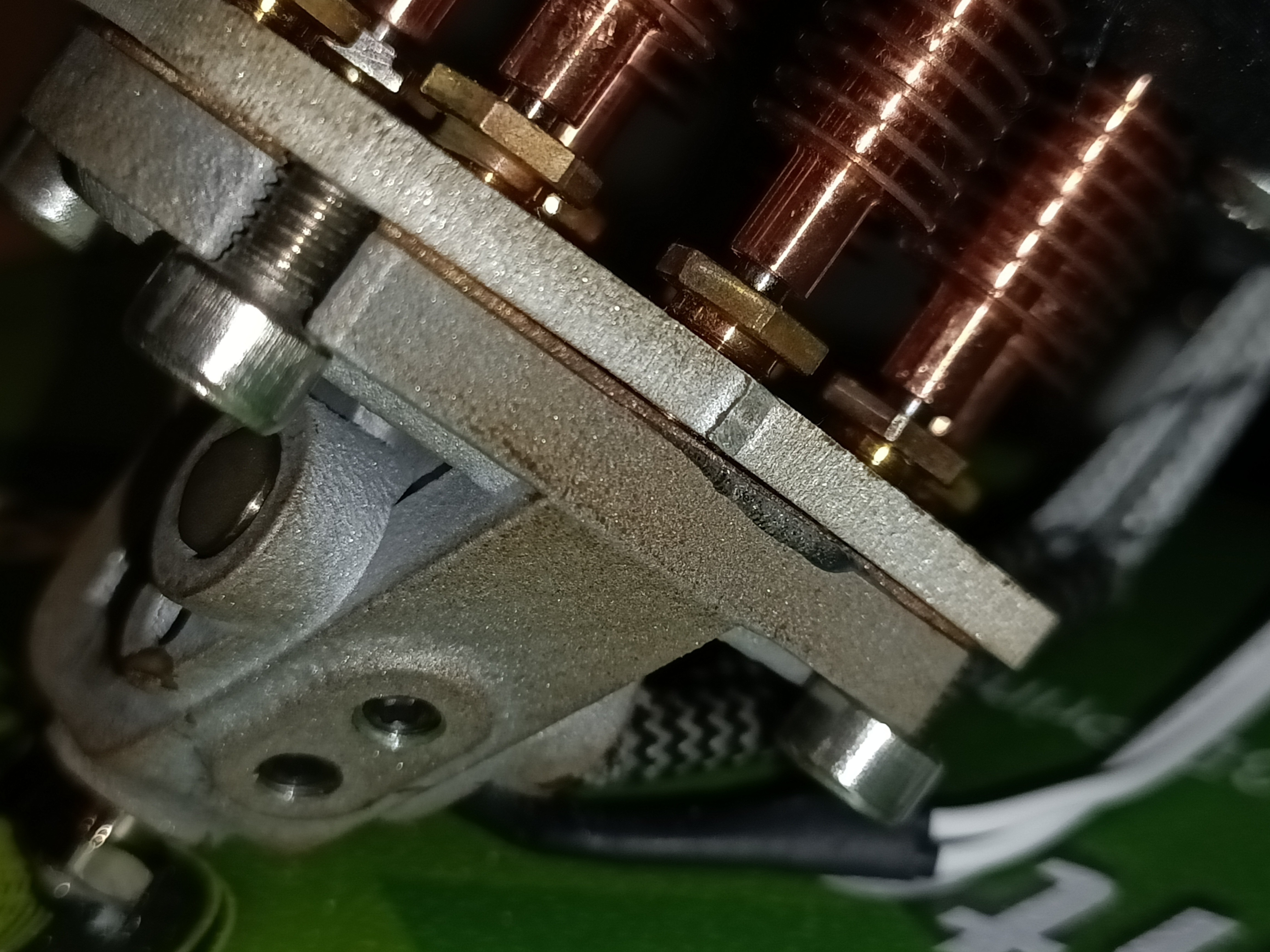

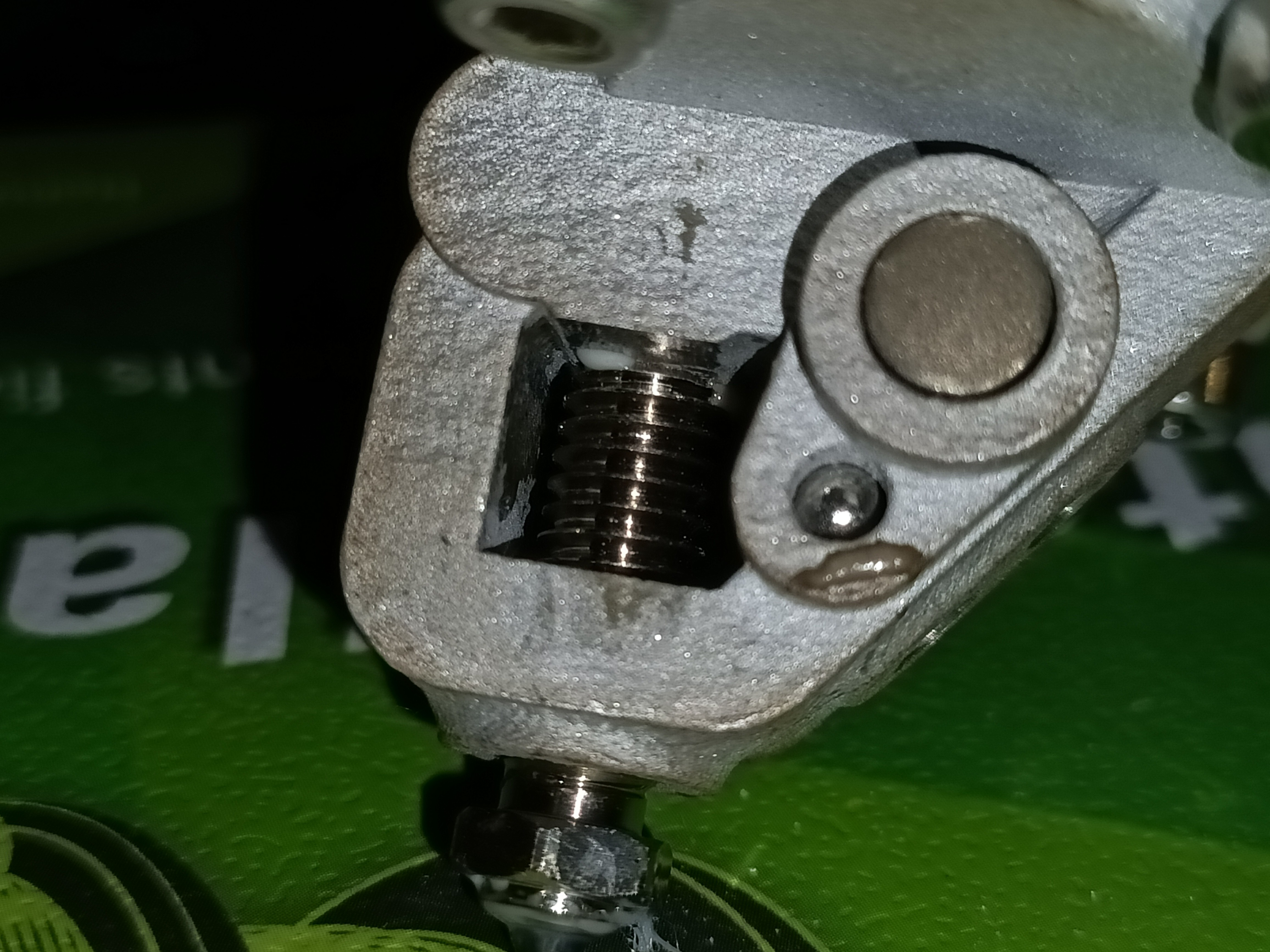
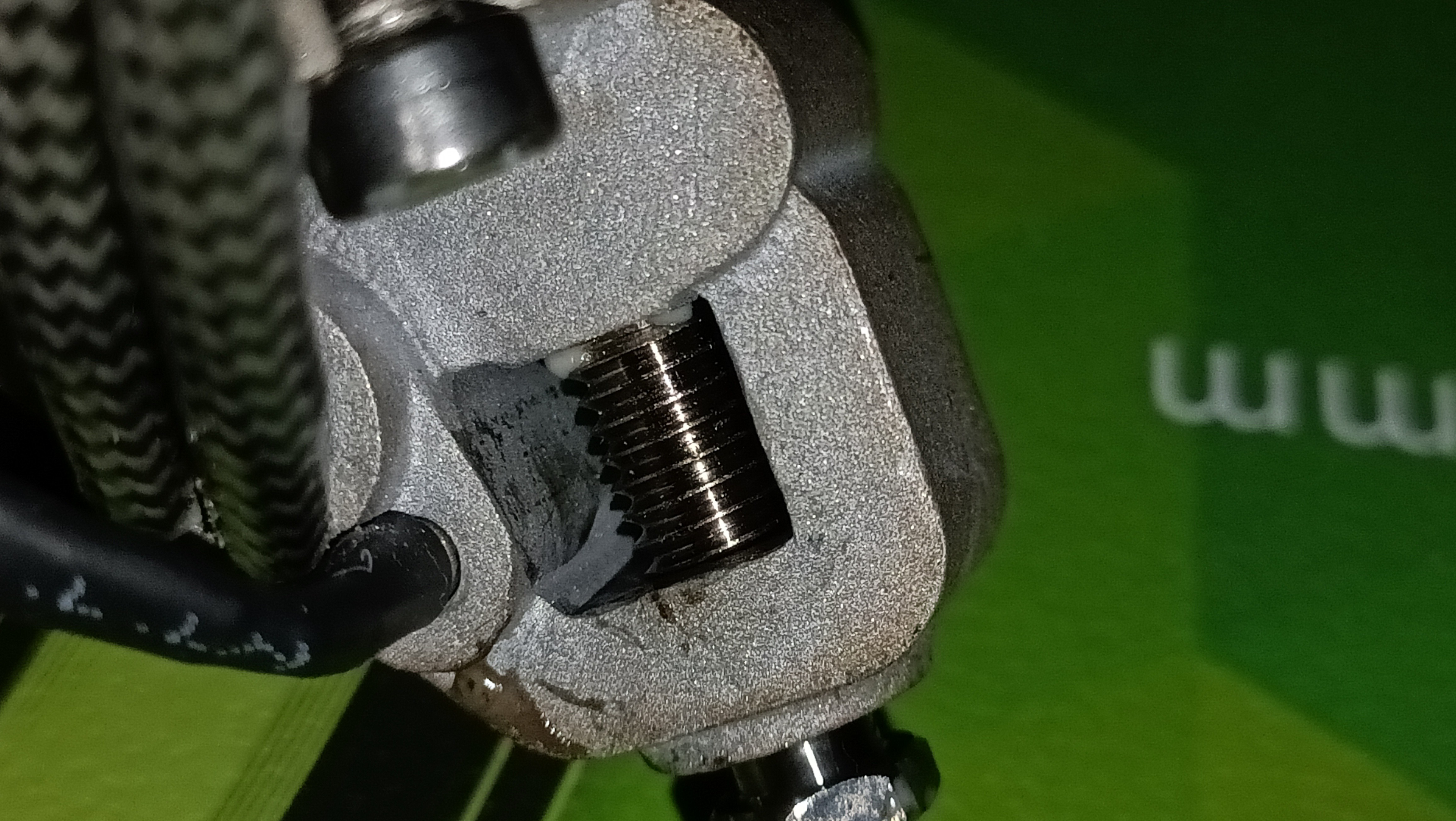
Thus, my next course of action is to get a new clamp plate out of steel and perhaps a copper gasket for the output:
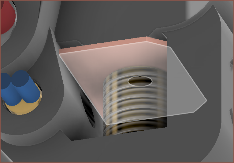
The next sealing strategy is to use Kapton tape, which has a continuous operating temperature of 250C and should allow printing of all but perhaps Nylon (CC3D PBT Pro sounds like a good alternative from reviewers) and Polycarbonate (and ultra high temp materials that would exceed the thermistor). I've got 5mm tape so I could try it.
Removing the gasket
I noticed that both input leaks are happening under the copper plate. Perhaps it's causing the leaks in the first place. My hypothesis is that 0.7mm is too thick of a gasket for this application.
I was able to use the cover as a hotend holder:
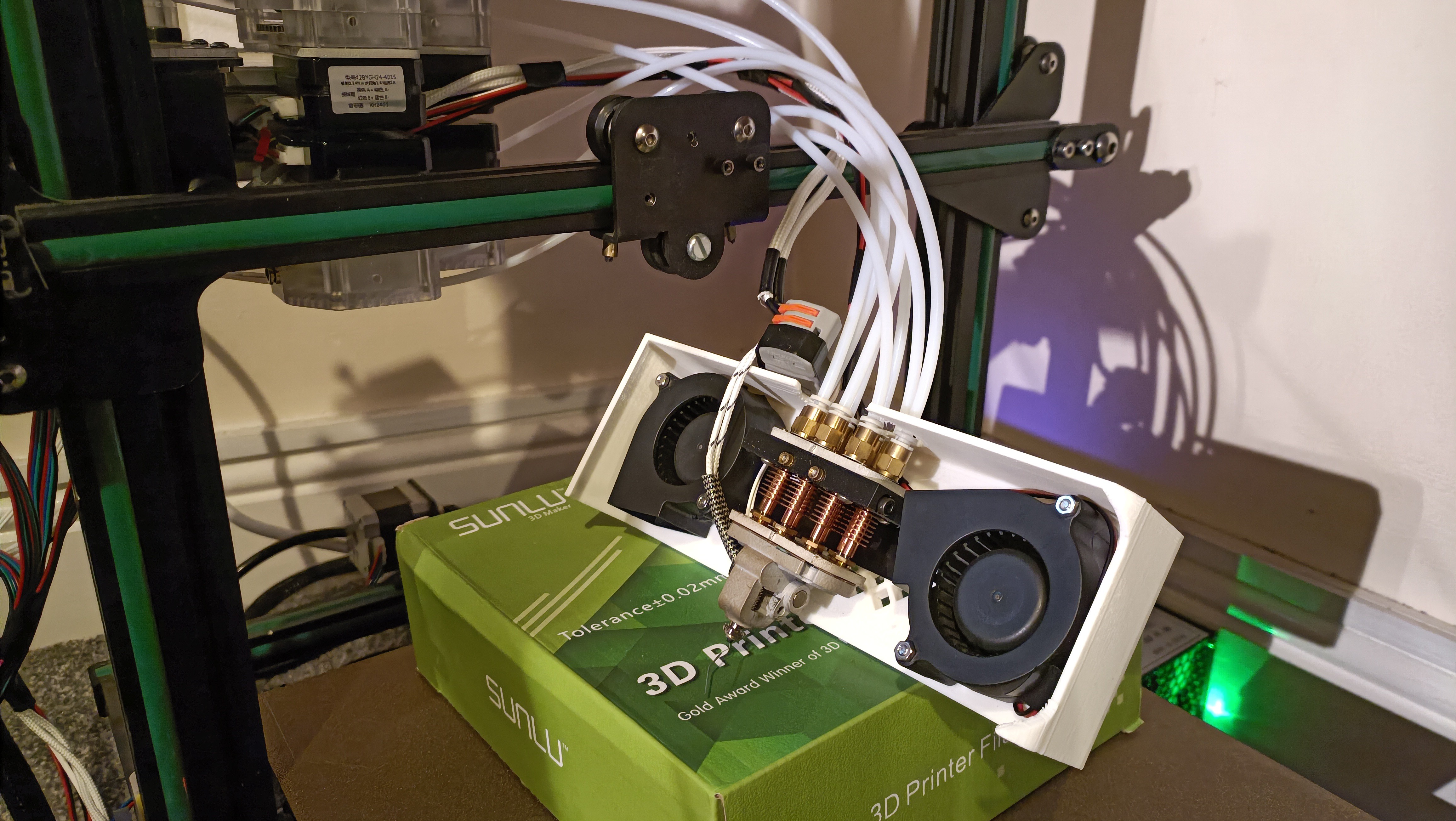 Heated to 220C, unloaded all filament, cooled to 130C and pulled the c8or apart from the clamp plate. There was material in the heatbreaks and I was able to remove all but 2 channels (TransBlue and Yellow). The modal length is 8.5mm, with 7mm, 11mm and 12mm lengths being cyan, white and transparent respectively. It seems this is approximately where the first copper fin starts.
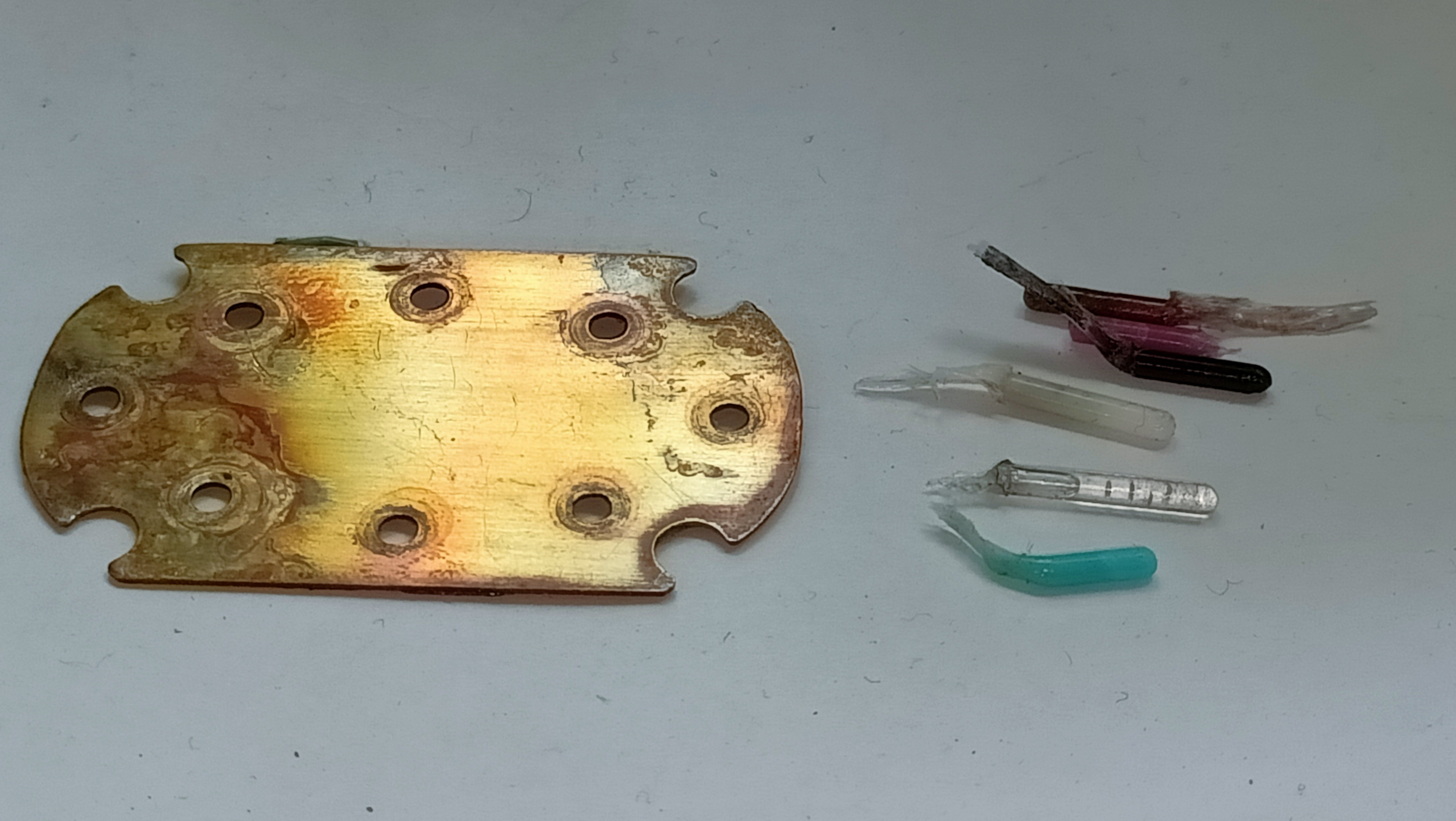
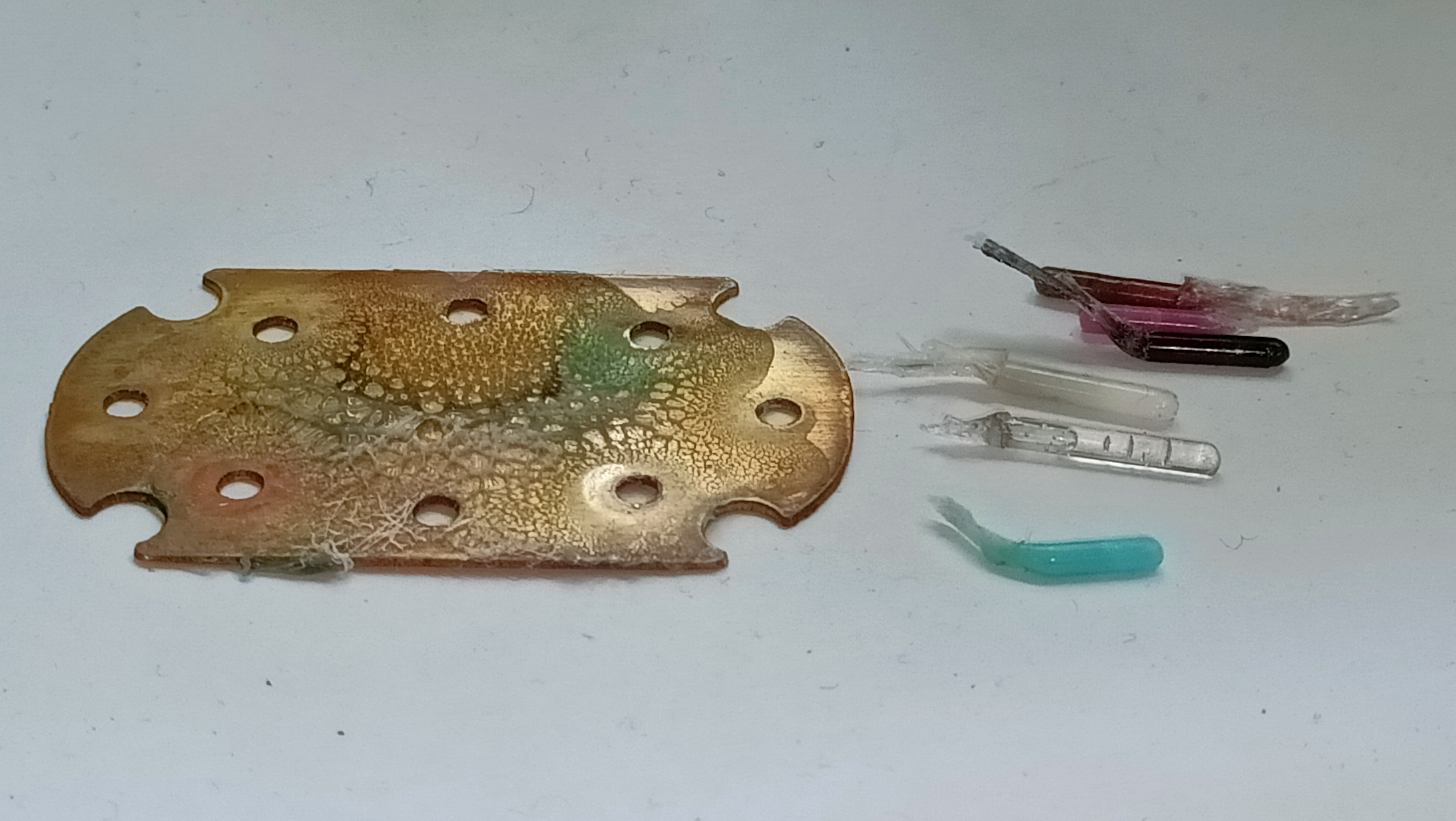 Indeed, it's the seal between the gasket and the c8or that doesn't work, not the seal between the gasket and heatbreaks.
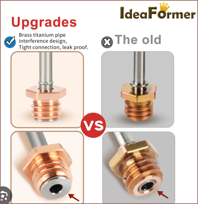
In actuality, it might be that the heatbreaks actually come with a built in "sealing washer" and so an additional gasket is counterproductive:
Cleaning attempt
I tried to heat the block to 180C so that I could wipe off the material, but instead, material from the chanels started expanding out (creepily) and so I turned off the heat. I wondered if I could use this to my advantage and pull the rest of the material with the small blobs that came out, but it just pulled out material from within the c8or.
I was going to try and use emery cloth, but the thermistor is stuck inside for some reason. In contrast, the heater cartridge was actually loose and came out without even unscrewing the grub.
I tried melting a strand of filament on the thin film of plastic but it didn't pull off with the filament.
 kelvinA
Discussions
Become a Hackaday.io Member
Create an account to leave a comment. Already have an account? Log In.