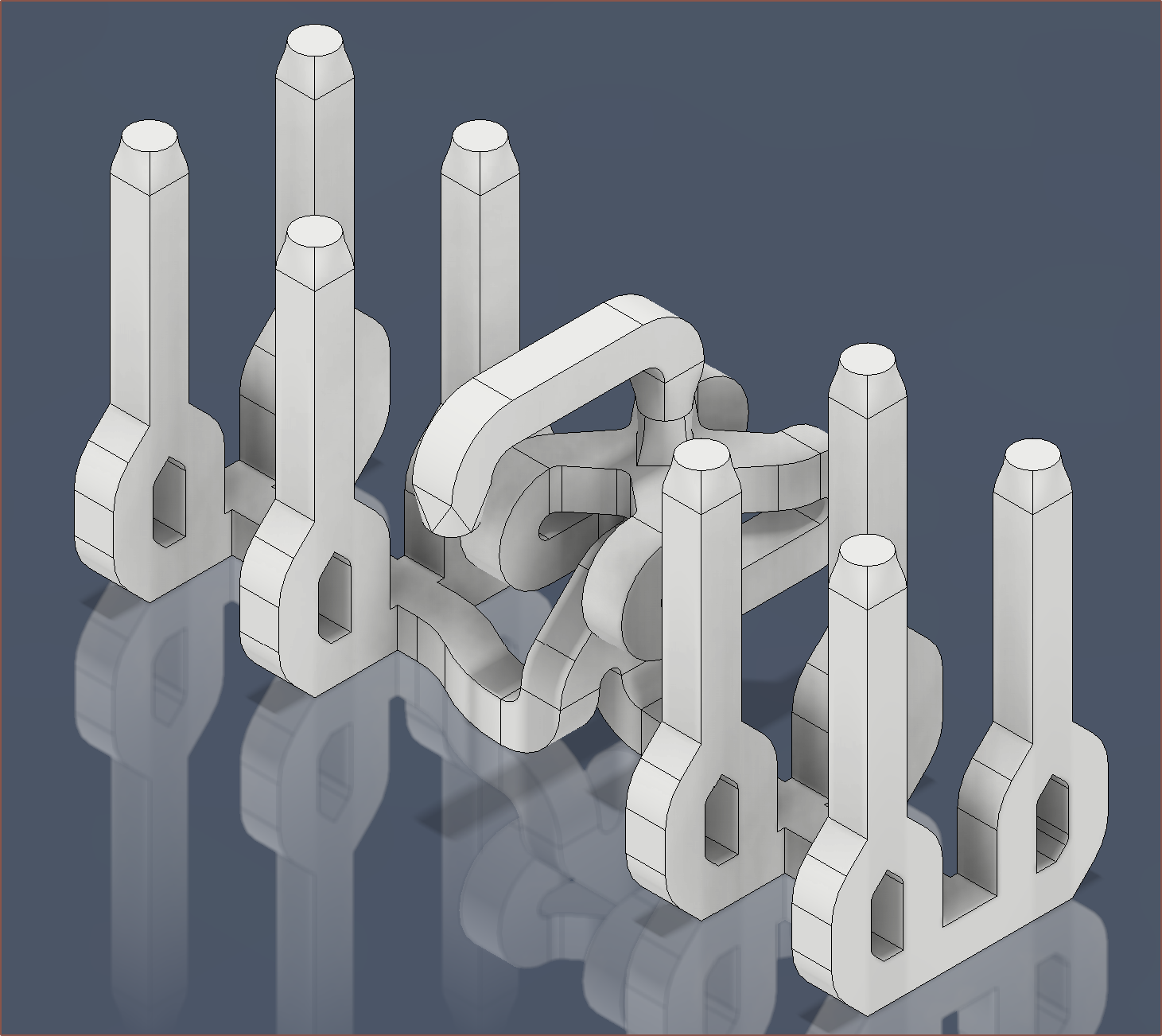
 So, instead of trying to print ABS-core PETG to test before buying and trying a stiffer 64D TPU (compared to the presumably 95A TPU I have now), I've been wanting to implement some improvements into CAD:
- single-channel flow rate
- heater cartridge choice and mounting
- sealing
- post-processing without expensive machinery
I expect that this TPU would be most ideal to use as glue/core, but part of the reason for the higher melt time is ideally to make standard TPU more likely to print successfully. Additionally, I suspect that my flow rate is still limited at around 10mm/s/channel, which is not enough for my usual layer height at any reasonable speed, limited to under 40mm/s.
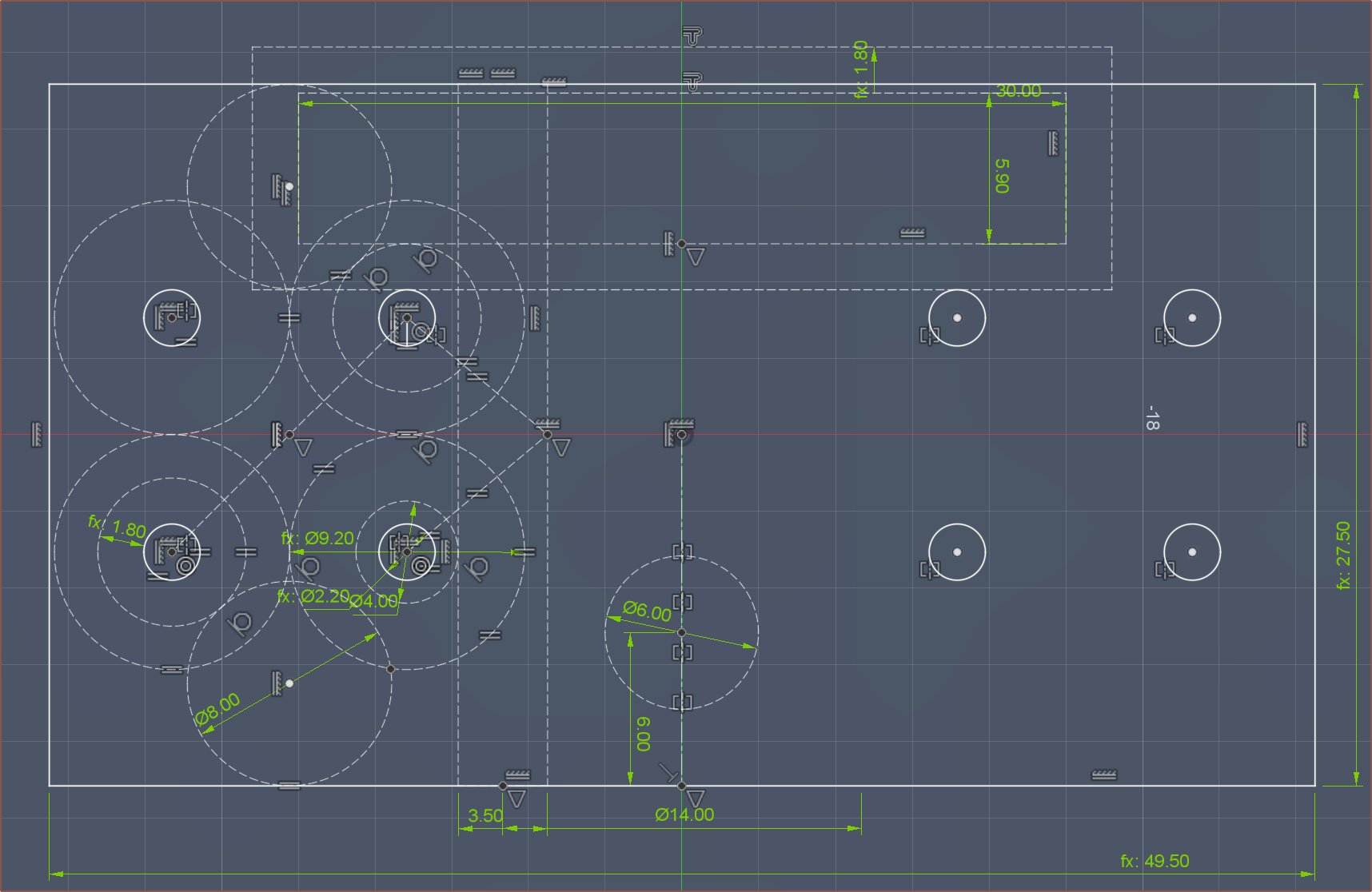
To increase "yields" of clamp plates (i.e. a plate where all M6 threads are perpendicular), as well as give space for the heatbreak tightening spanner, I've moved the inputs to 2 squares of 4. This way, I only need half as many threads per plate. It's better to have to redo the plate if the 3rd thread was bent instead of the 7th. I also hope this would make alignment to the couplers easier.
The plan is to then heat this with a 30mm long, 160W cartridge. Hopefully, I don't need to use a 47mm, 320W cartridge. I'll use a clamp design, which should also allow 20mm cartridges to be used.
As expected, the immediate 90-degree bend doesn't fair well when it comes to flow rate. As seen in the topmost image, my plan was to have a straight path to the bottom, then go back upwards with the coaxialiser before outputting to the nozzle. Additionally, I had recently seen the below video on tests done with multiple 2D path geometries:
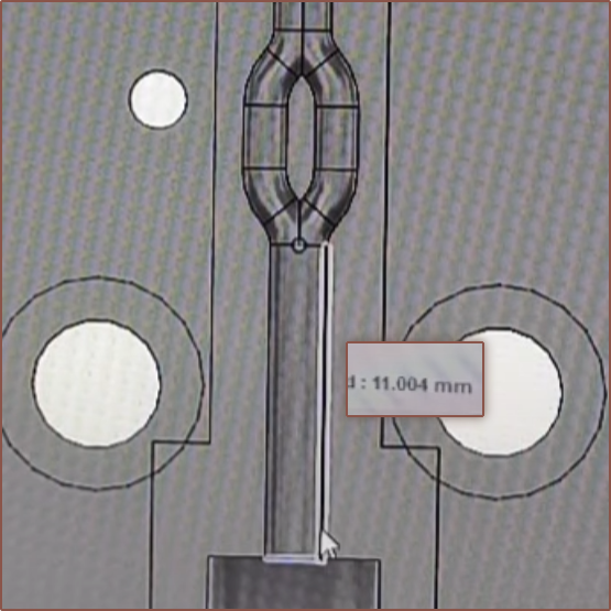
He obtained good results with a straight-length distance of 11mm before the split. He also tried a 4mm length before the split and flow rate was worse than no split at all. The split distance in my design is 13mm. The drawback is that the high-flow columns alone will store 1250mm^3 (2/3rds total) of material in them. The R2 has less than 1000mm^3 entirely.
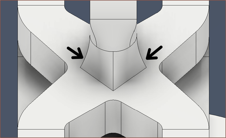
My only slight concern is the output directly after the coaxialiser since it's sloped such that it could become too steep an overhang when the part is printed at a 45 degree angle:
 There was also a noteworthy comment left in the video above:
I think there is a flawed assumption by the community that smooth bore=better flow, that seems so obvious that nobody questions it, so nobody tries anything else.
I did an experiment polishing a 100mm long bore [...]. Instead of being shiny and polished, it was like the "orange peel" of a bad automotive paint job. I tested it anyway, and the results were a 30% improvement over any previous test!
Since then I have tried several similar strategies to intentionally "ruin" my barrels: scouring with stainless wire, running a tap into the bore, running a dull drill bit through it, etc.. All the tests either show an improvement or no improvement over smooth bore, but none perform worse.
I have several theories about why, but my two favorite are that the rough surface creates turbulent flow, mixing hotter fluid at the perimeter with cooler fluid in the center, and that a rough surface is more surface, and more surface = more heat transfer.
Thus, I don't think I need to concern myself about the surface roughness of DLMS parts, and just need to ensure that overhangs don't exceed 45 degrees.
I also like that this design is more accepting of arbitrary input amounts. The only thing stopping someone from a Coaxielveor (12-in-1-out) or Coaxihexor (16-in-1-out, not to be confused with a Coaxi6or) are other things like software / firmware / hardware support.
[Oct 12]
I decided to take a loft straight from the coaxialiser to the output pipe, which looks cool and seems printable. I've then simulated it and it takes 4.5s for the output to transition.
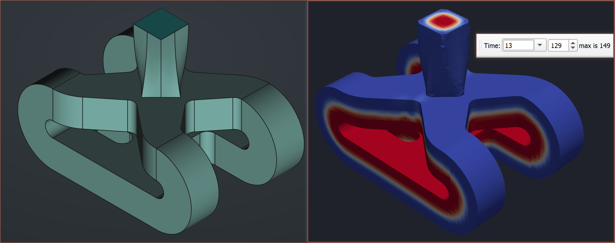 The coaxialised output conforms to the cross section. The below images show the output just as it leaves the coaxialiser (left), halfway up the loft (middle) and the end of the loft (right):
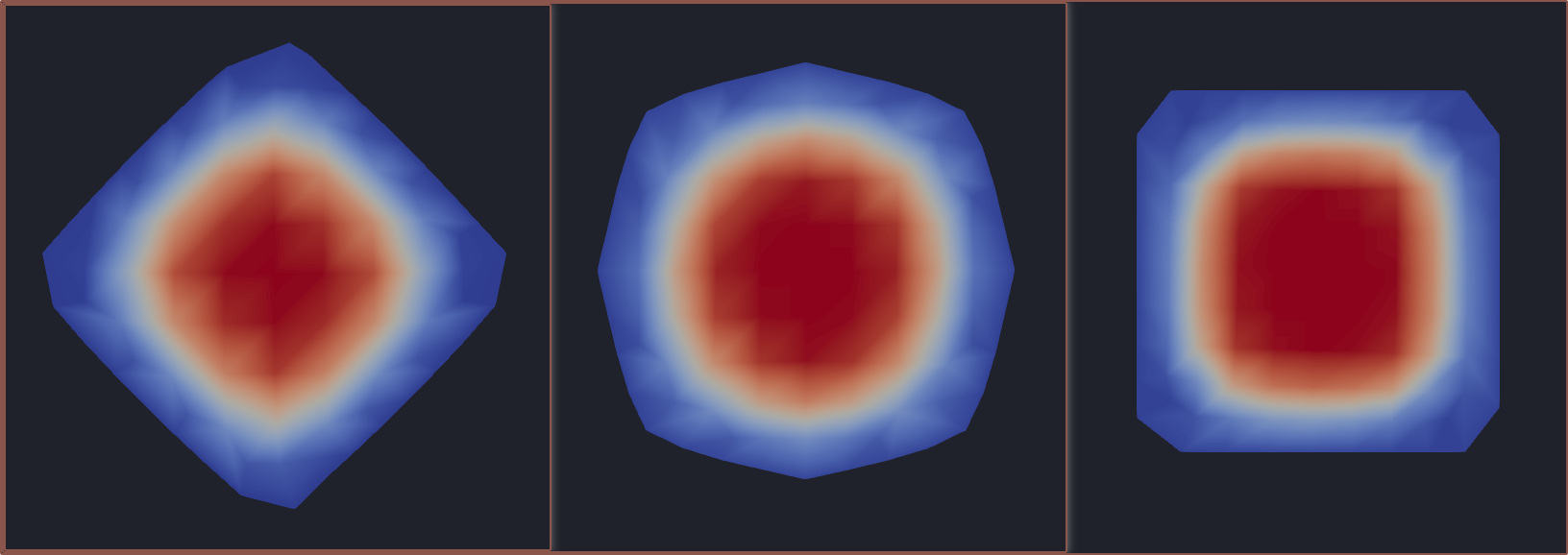 I notice that the midpoint is notably rounder than the simulated output of R2:
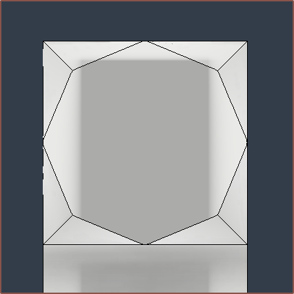
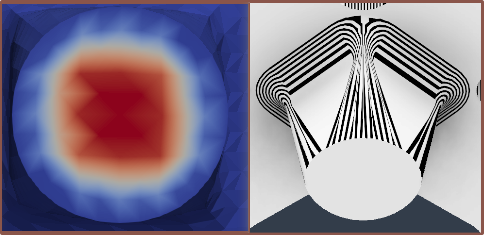 Thus, I've modelled an octagon output instead:
 kelvinA
Discussions
Become a Hackaday.io Member
Create an account to leave a comment. Already have an account? Log In.