 kelvinA
So after spending some days wondering what to print (and finding out Orca will throw out all my settings if I open a .3MF with some,) I decided that I was going to tune scarf seams and M592.
Seams
I started off by learning the research posted in this guide on Printables and its comment section and applying it to a tesseract 3D model because "what point is a test print if you have confidence it'll print fine?".
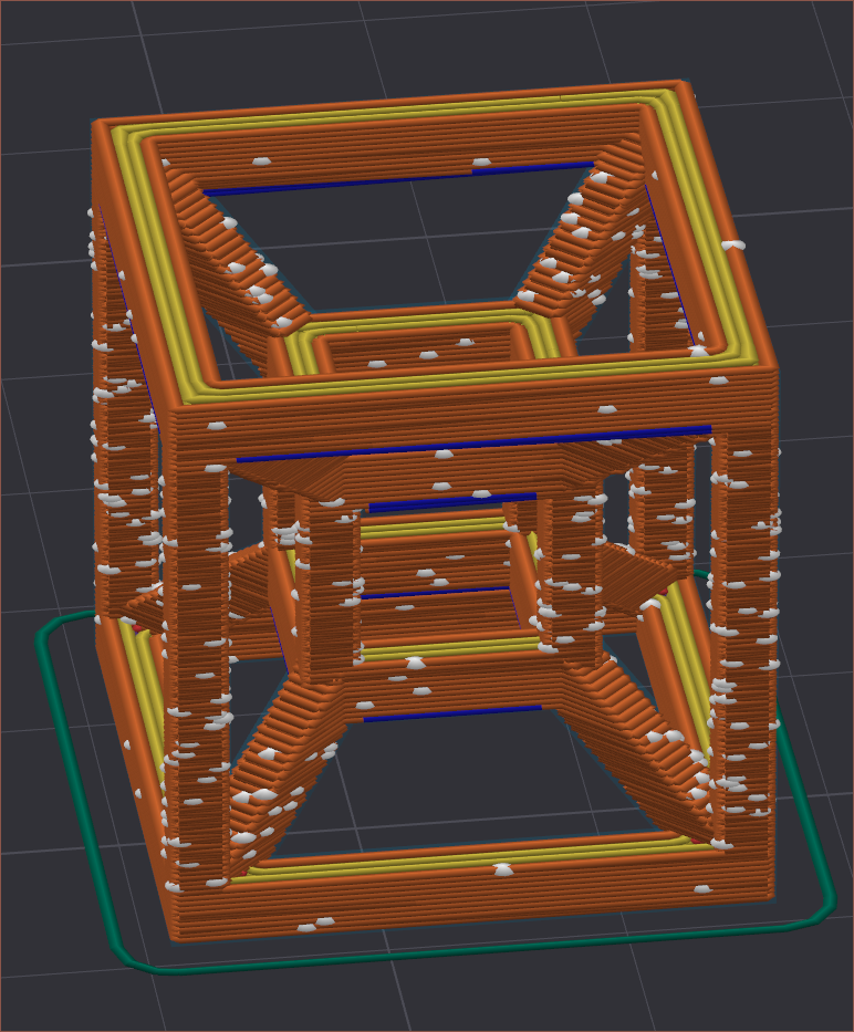
I changed the z-seam location from random to aligned because some layers would try and start on an overhang.
I tested things like Inner/Outer vs Inner/Outer/Inner and, even with the latter looking questionable in the 90-degree overhang section (see below), I watched the print and came to the same conclusion that it's better.
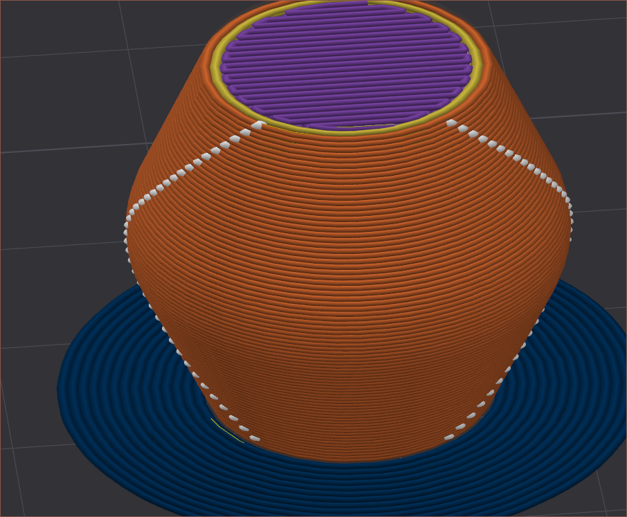
I also set the bridge acceleration to 150mm/s2 which greatly improved the bridge actually anchoring to already-printed sections. I'll need to test more on a dedicated .STL in the future, but looking at the string left at the end of every print (as the hotend moves to the upper left corner over 20cm away), I think the strategy is low extrusion multiplier and low acceleration.
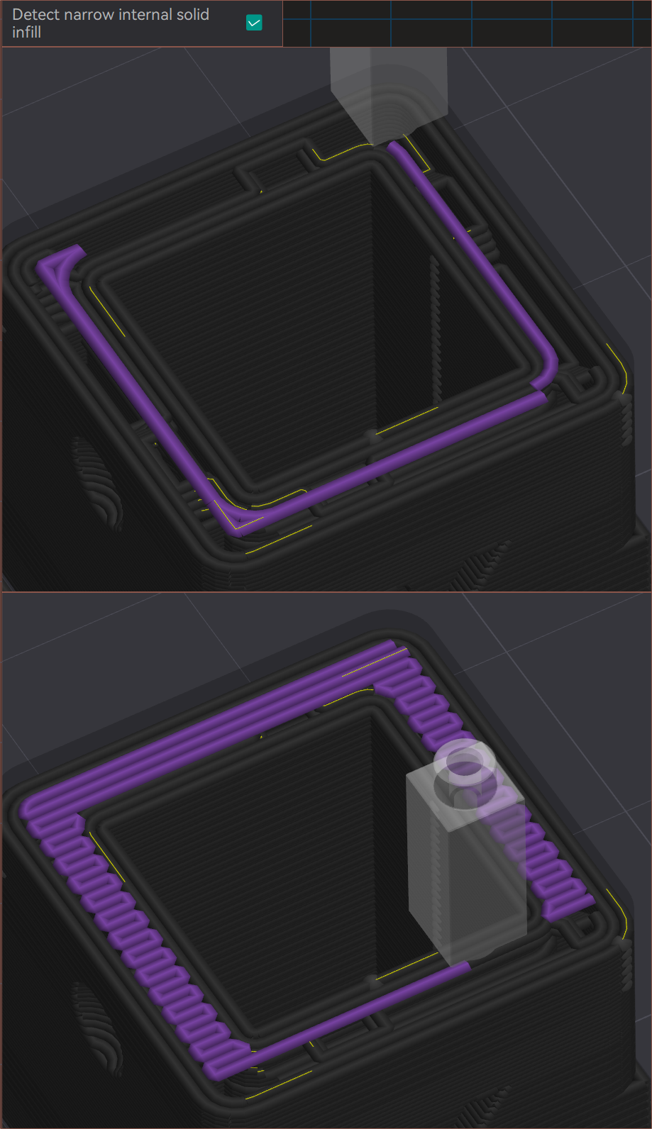
I tried a ripple cube STL I downloaded probably a dozen of years ago to see my current results on an easier print, and I had to turn off "Detect narrow internal solid infill" because it would try and bridge in midair:
I enabled Mesh Bed Levelling to help mitigate the first layer issues I had been having. I should've tried MBL out way earlier. A fade height of 3mm looked to be fine, considering my bed is only warped by 0.4mm.
I then moved onto this model to better see what the seams were doing:
I tested:
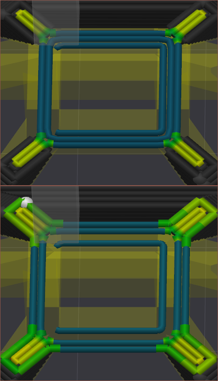
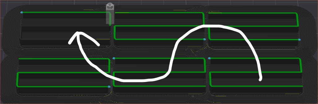
- Wipe retract percent of 100% and 0%
- I was going to try 50%, but 0% was miles better than 100% that I didn't even bother. I believe it's because the printer has to momentarily pause to do the retraction, causing a secondary "seam" (shown in white in the image above)
- Scarf start height of 12.5%, 0% and 25%
- I've got staggered seams enabled, and 25% looked the neatest.
- Seam gap 6%, 50%, 0%
- 50% just spaced out the seams.
- 0% was slightly more compact than 6%
- Wipe before external loop
- I didn't have it enabled and the seam stuck out a lot less when it was.
- Wipe length 3, 6, 1.5mm
- 6 slightly better than 3 which was notably better than 1.5.
- I remained on 3mm.
M592
As I was printing, I noticed that my infill line wasn't starting all that well, and thought of an idea to test M592 Nonlinear Extrusion.
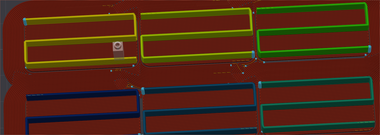
The yellow line is fullspeed, which should be 15mm3/s. This seemed to correspond to around 72mm/s, so I went up in units of 12mm/s for the other 5. For some reason, the slicer decided to print in the following order:
The fastest one was the only one that didn't quite start the extrusion right, but all of them had varying line widths from the start (blue dot) to the end of the line.
- 12mm/s would start at 1.2mm and end at around .9
- 60mm/s would start at 0.6mm and end at around .7
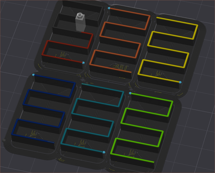
A bunch of trail and testing later and the results were inconclusive. I decided to rotate the pieces to give more time for the extrusion to equalise:
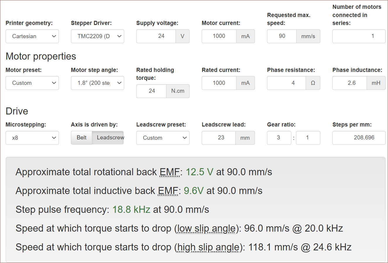
I just knew that I needed to do something about improving linear advance. One idea was a lower max e-speed in exchange for higher e-acceleration. When going into the tests, I had 120mm/s and 600mm/s2. I guesstimate to try 90mm/s, which was confirmed by using a calculator I found:
Dropping to 90mm/s, I used 0.9 k-factor to induce many E-movements and found that 3000mm/s2 worked but 3600mm/s2 had a slew of skipped steps. I then tried 0.45 and 0.6 and the latter was the best. This seems to agree with the setting found by an Ender 3 owner:
I was holding the filament during the print (to gather data on how the k-factor affected the movement) and the haptics of the 24mm/s line was quite nice. I hope to implement the feeling into #Tetrinsic [gd0041] in the future. I was also able to feel retractions, and I think 90/30 mm/s for 3mm retract/deretract respectively are good settings.
Discussions
Become a Hackaday.io Member
Create an account to leave a comment. Already have an account? Log In.