 kelvinA
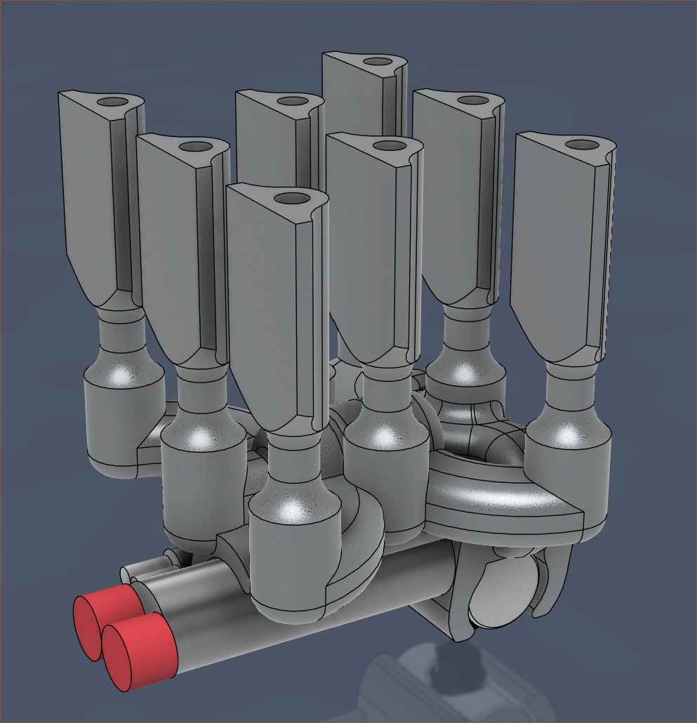
I wondered if it would be a decent idea to try a solution without the complexity of the heatvalves as more of an engineering sample that focuses on validating if the new internal geometry even reduces the transition volume to an acceptable level.
The above design is 5.0 cm3, which is more than half of R2. This design doesn't use a clamp plate, which contributed another 3.5 cm3 of hot-metal volume to R2. However, since I'm still unsure about being able to use boron nitride paste to hold the cartridges, this value is likely to increase.
The spacing between inputs is 10.5mm. I tried 10mm (like in previous revisions) but the front-corner inputs come too close to the coaxialiser.
I tried to squeeze the heatbreaks to as little volume as possible because they really do add up when there are 8 of them. They also have to be short to ensure that the drill (and reamer) can reach. Each one is 0.23 cm3. There's only a little less than 6mm of space between rows, so I considered both heatpipes and heatsinks. I modelled 2 different 5mm-high heatsinks I found on AliExpress:

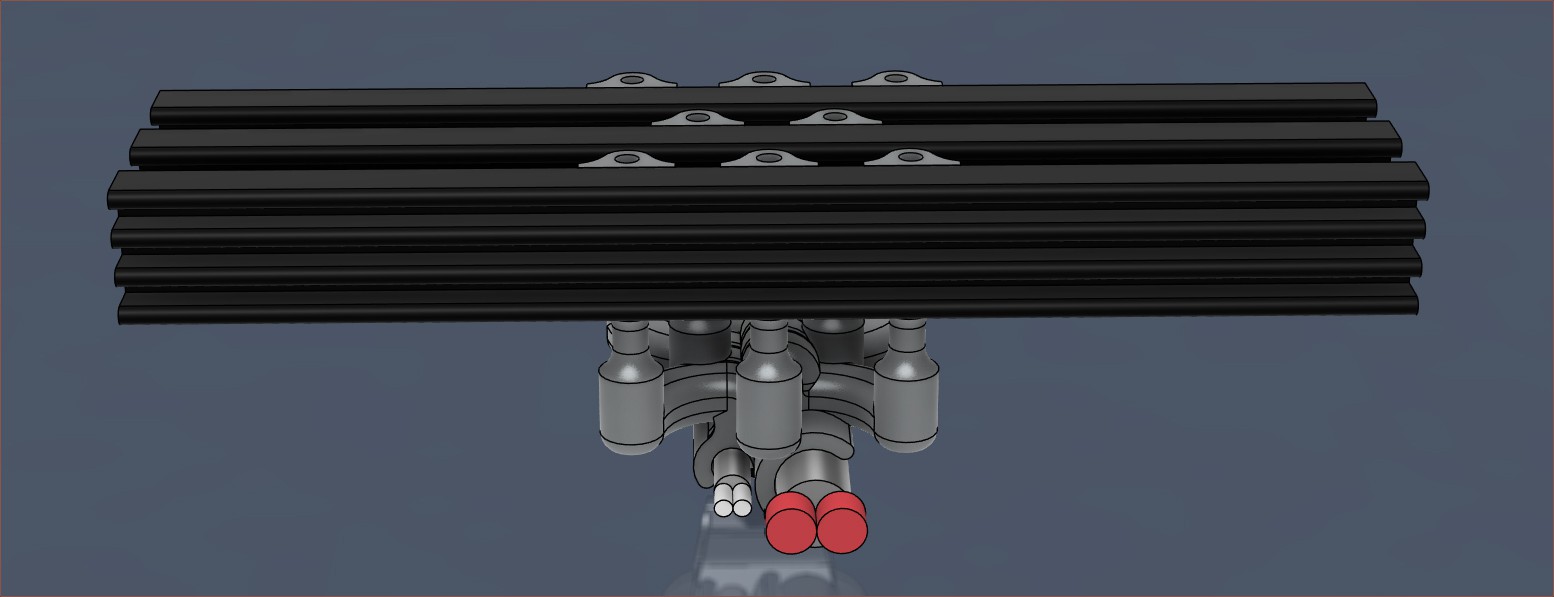
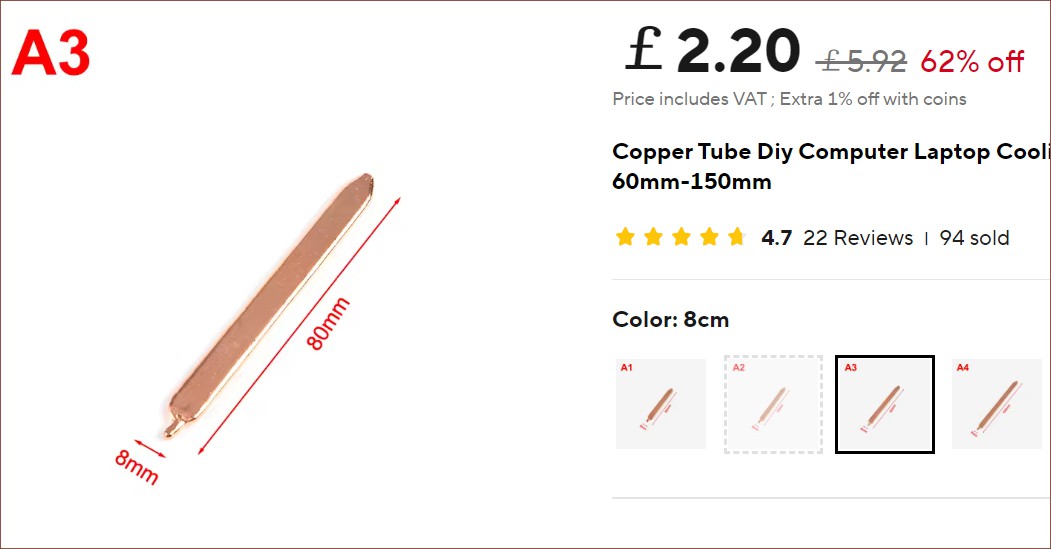
When divided by 3, the 100mm one is a little over 1000 mm2 per input. For aluminium, this might be too low. Even if it was adequate, fitting the fan would likely be a challenge. Thus, the heatpipe option is more likely; the flat ones on AliExpress are 8mm wide and 3mm tall, starting at 60mm long.
Discussions
Become a Hackaday.io Member
Create an account to leave a comment. Already have an account? Log In.