This project is an attempt to understand how RRIO opamp work internally, and to replicate one with very common components.
Goals
While the learning part is the bootstrap of the intention here, we want to have a real opamp at the end of the journey.
Main objective
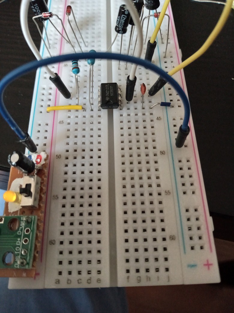
The main design goal is to leverage components as common as possible. That includes passive components, such as resistors & condensators, but also very common IC. Which includes ones like the LM358 for opamps of course, but also the NE555, so it could even participate in the now-defunct NE555 challenge.
Using another LM358 instead of a NE555 might be interesting for the sake of staying withing the opamp challenge, but it might go against the secondary objective.
Secondary objective
An SMD version of this circuit should be aimed to be a pin-compatible DIP-8 version of the most common dual opamps for an elevated challenge. If DIP-8 proves to be too complex, we can aim for a pin-compatible quad-op in a DIP-14 format.
Design
The design here is very easy.
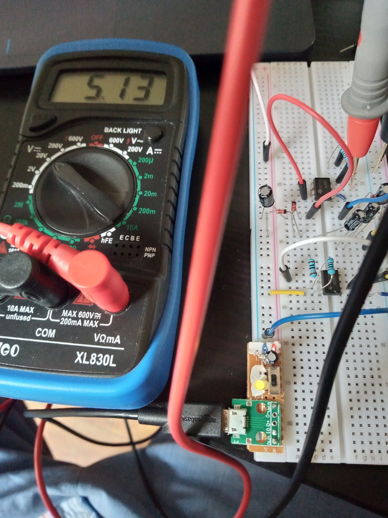
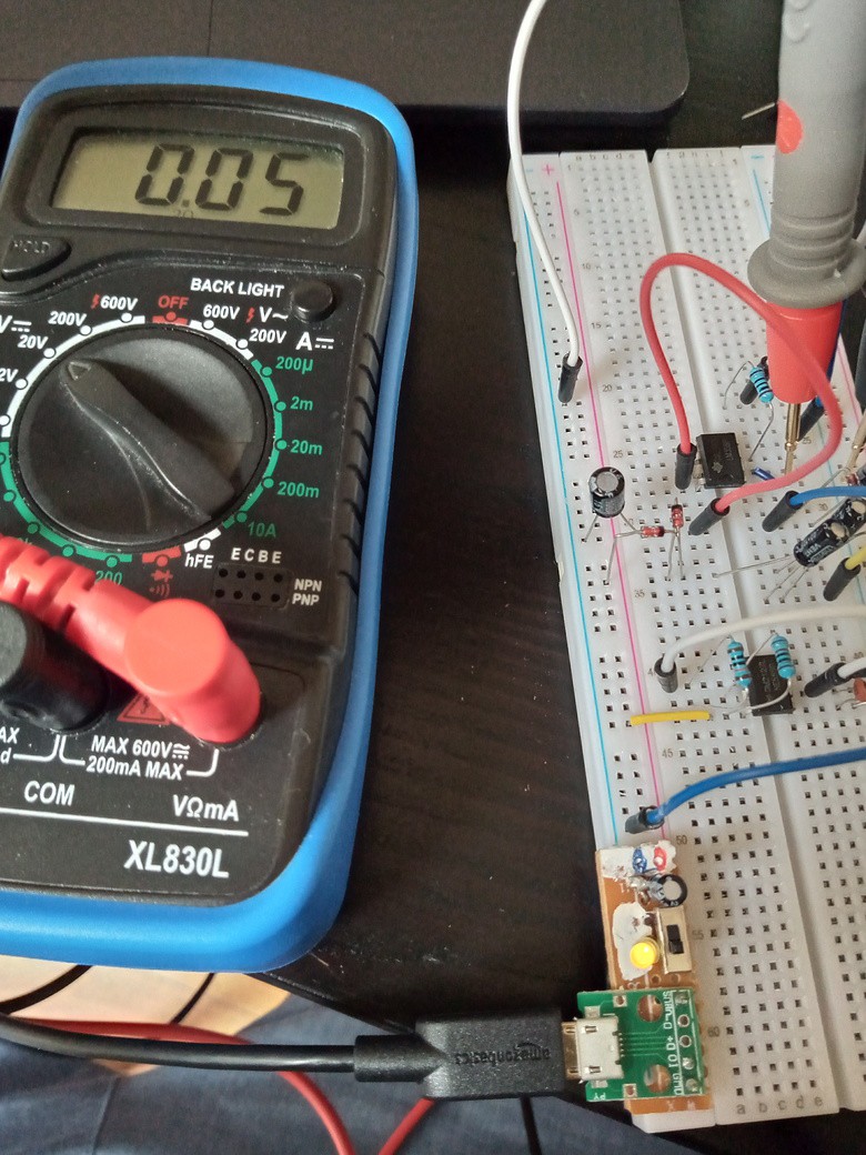
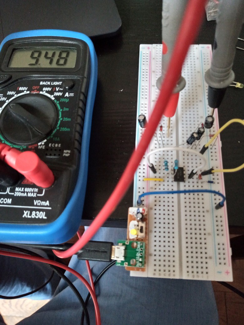
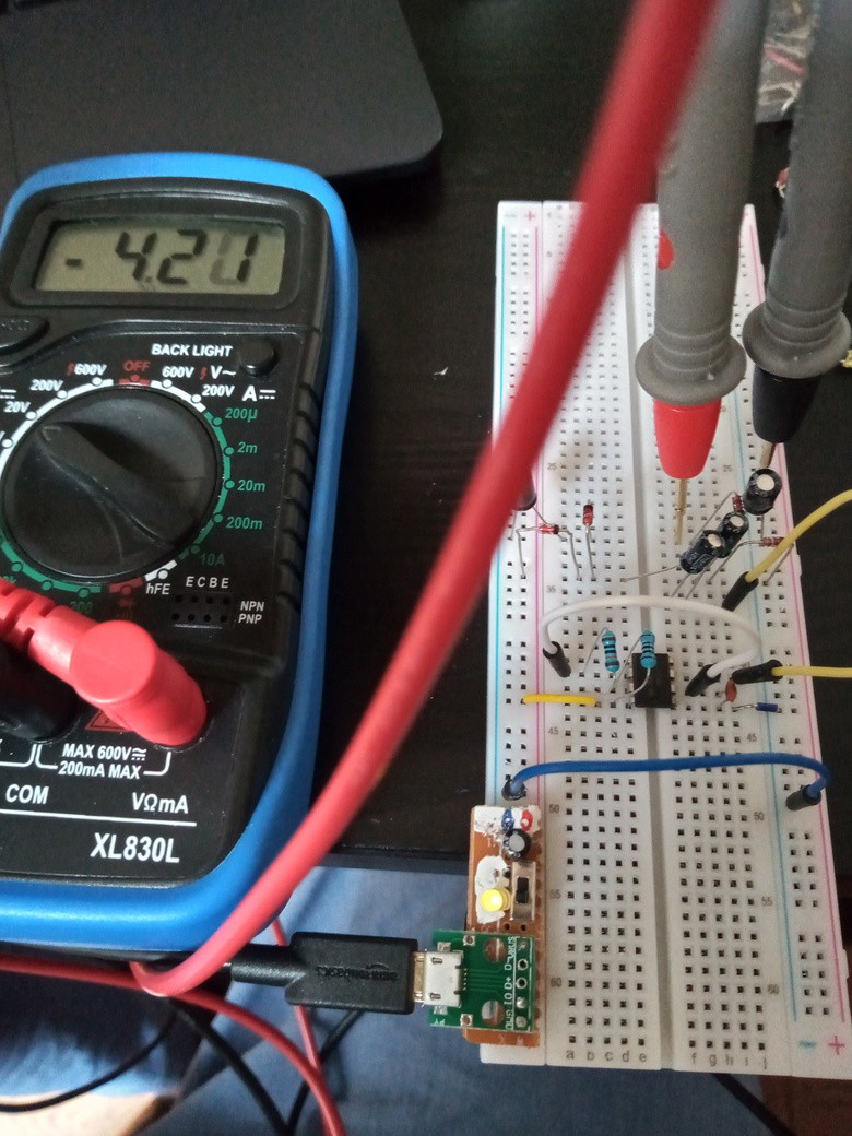
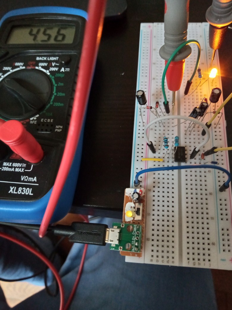
To be able to put the LM358 in RRIO mode, I'm simply cheating and supply it with single voltage source that is has a little more amplitude than the main voltage source.
This is to overcome the various voltage drops that are inherent to the internal LM358 construction.
The simplest way to achieve it is a capactive charge pump. This is incidentally the same way that many RRIO achieve input rail-to-rail. Output rail-to-rail is usually done with a CMOS buffer instead of the charge pump, in order to limit the current need on the pump and be able to fit it directly inside the die of the IC.
I don't plan to add the CMOS output buffer, but instead generate a charge pump powerful enough to also be able to drive the opamp load directly.
 Steve Schnepp

LM358's common mode and output range extend to ground. The 50uA output sinking capability below about 0.8V can be vastly improved by adding a current sink. It can be just a pull-down resistor, or an active bipolar or mosfet sink. Low conductance NMOS devices in the CD4007 chip make great sink current sources, and give quite a bit of an improvement. Extending the range to V+ requires some sort of a boost converter, exactly as you show. This is a neat idea!