-
1PCB - Design & Build
KiCad & PCB
Being my first PCB ever, I started from scratch with KiCad Like a Pro 3rd edition in Udemy which gave me a basic understanding both of Kicad 6 and of PCB design. The course author also has a playlist on his YouTube channel with examples and key terms.
Some additional sources:
- How to improve your PCB designs (common mistakes) - Phil's Lab
- The importance of trace widths - SF Circuits PCB School
- The Hitchhiker's Guide to PCB Design
- Contextual Electronics Apprenticeship
Capacitive Touch Sensing
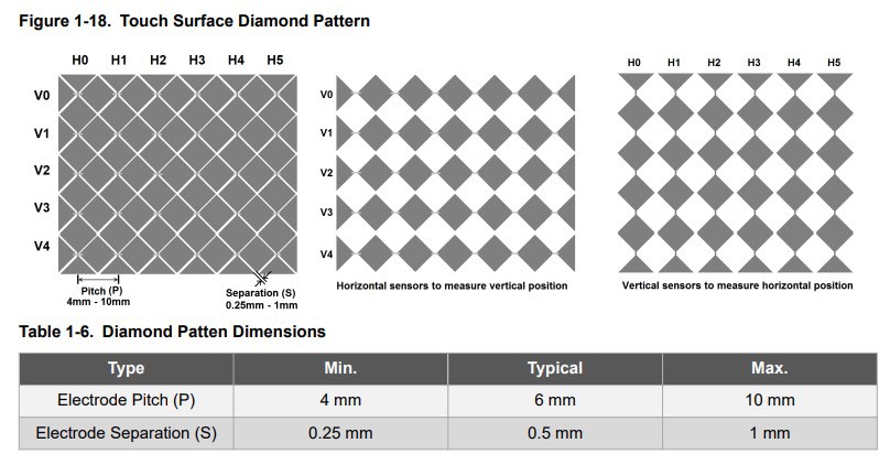
At the same time, I researched about capacitive touch sensing, starting with main concepts, common challenges and basic guidance, with focus on touch surfaces (as opposed to touch buttons) in self-capacitance sensors. From Microhip's Applications Notes AN2934 page 13 (Capacitive Touch Sensor Design Guide).
![]()
After this basic knowledge, more specifics are found in NXP's AN3863: Designing Touch Sensing Electrodes, specifically:
- Item 3.1 Traces, page 4 for clearance, width & routing
- Item 3.2 Electrode Pattern Design, page 6
- Item 3.3 Electrode Placement, page 7
- Item 3.4 Correct use of Planes, page 8
- Item 3.6 Virtual Ground and Considerations in Battery Operated Applications, pg 11
- Item 4.5 Electrode Patterns: Touchpad, page 25
The following image from KiCad shows the front of the PCB with its 22 x 14 TEs, each with 2x3 copper pads. All pads are 4mm square, with 0.8mm separation if within a TE and 1.6mm between TE's.
![]()
Letterboard's Touch Matrix
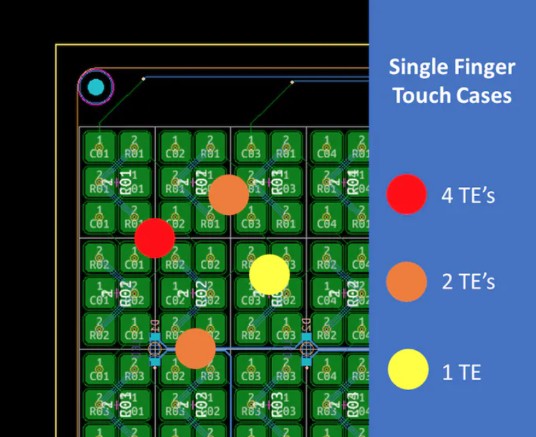
The letterboard´s touch matrix operates with a single-finger touch, so it's designed to have a minimum of 1 and a maximum of four Touch Electrodes (TE) touched at any one time and always at least one row and one column. Any other case is filtered out in code (i.e. when multitouch or touched at the edges)
There are 3 possible touch cases (pads are identified in the KiCad PCB file with Cxx and Rxx for Column and Row number):
- Intersection of 4 TE's (in red)
- intersection of 2 TE's (in orange)
- Intersection of a single TE's row & column pads.
![]()
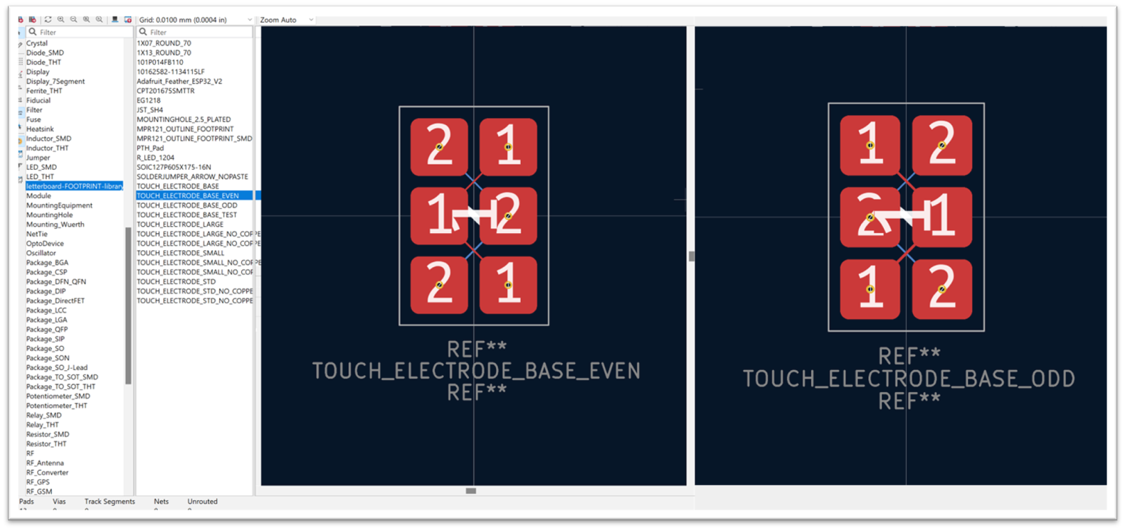
This layout required custom PCB symbols. I started learning it from atomic14's KiCad Tutorial: Custom Symbol, Footprint and 3D Model and then from my own discussions in the KiCad forum to use SMD pads as touch sensors with vias.
The letterboard has two kinds of TE's in the matrix: labeled EVEN and ODD for the number of the copper pad that's connected on the top layer and the copper pad that's connected using Via's in the bottom layer.
![]()
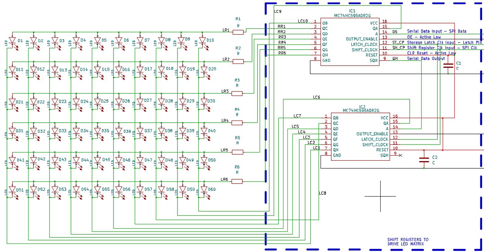
To keep distances to a minimum, odd columns connect to the top MPR121 and even columns to the bottom MPR121 with the rows connecting to the middle MPR121. This can be seen on the Touch Matrix portion of the Schematic:
![]()
Letterboard's LED Matrix
I got the basics from The Engineering Mindset's - LED Circuit Design (i.e. forward current & voltage, voltage drop, resistors, etc.) and from DroneBot Workshop's : Shift Registers with Arduino.
Then, to control a LED matrix (10x6 in my case), I consulted Mike Cook's LED Matrix Workshop, protostack's: Introduction to 74HC595 Shift Registers, and, Jegqamas': Control 8x8 LED matrix with two Shift Registers.
Armed with this knowledge, I chose NXP's 74HC595 SMD shift registers (datasheet) and Inolux's reverse mount SMD 1204 Amber LED (datasheet). The MAX7219 could be an option (see mdraber's: Controlling 8x8 Matrix with MAX7219), but it's price point made me go with the 74HC595's.
![]()
PCB Manufacture
I designed some small tests and sent them to JLCPCB (Manufacturing Capabilities) and then send the final files which triggered a discussion with their tech support people: Hot Air Solder Leveling (HASL) finish has a lower cost but would not be recommended for small copper pours. Instead, I ordered Electroless Nickel Immersion Gold (ENIG) finish. See picture for examples of potential bridging issues:
![]()
A comparison of HASL vs ENIG will show advantages and disadvantages of both. For a table comparing most finishing options, see here.
Finally, I had to learn to do SMD soldering, for which I started with Electronoobs' SMD Soldering Tutorial and EEVblog's SMD Stencil Reflow Soldering Tutorial. A very therapeutic experience I must say.
-
23D Printed Enclosure - Design & Build
Once I had a fully built and functional SMD soldered PCB came the turn to learn Fusion360, for which I started with wermy's Crash Course, then took Designing for 3D Printing with Fusion 360 in Udemy, then practiced with Product Design Online's various videos. Needless to say, this is like painting or writing: It will require practice for the rest of my life. :)
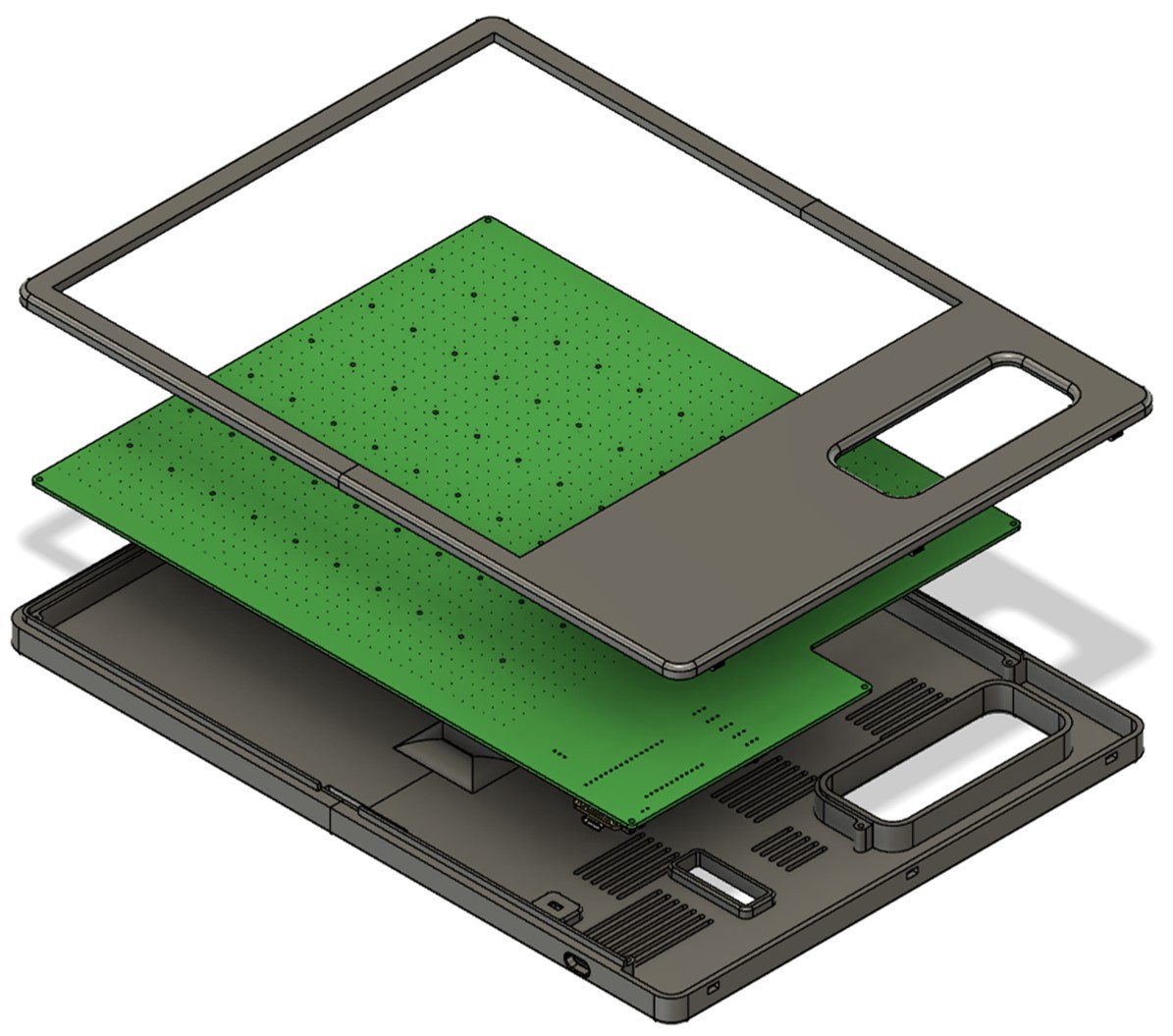
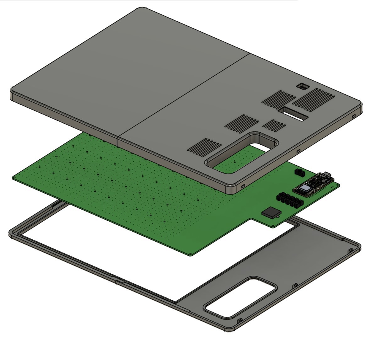
![]()
![]()
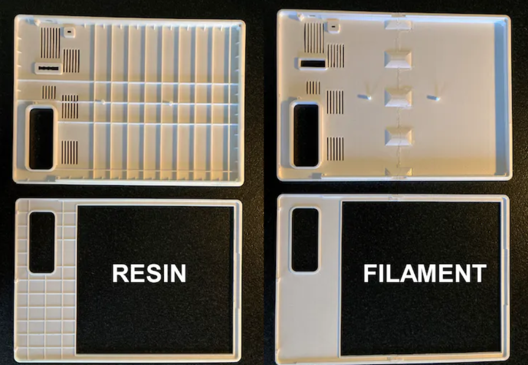
I sent for manufacture in JLCPCB a resin version and a filament version. Interesting to see the differences in texture and weight. For future 3D printing outsources, Craftcloud is a great place to use.
Resin resulted is a better finish, but a much higher weight and less precise dimensions. The filament enclosure was printed as separate parts and then glued together.
![]()
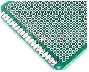
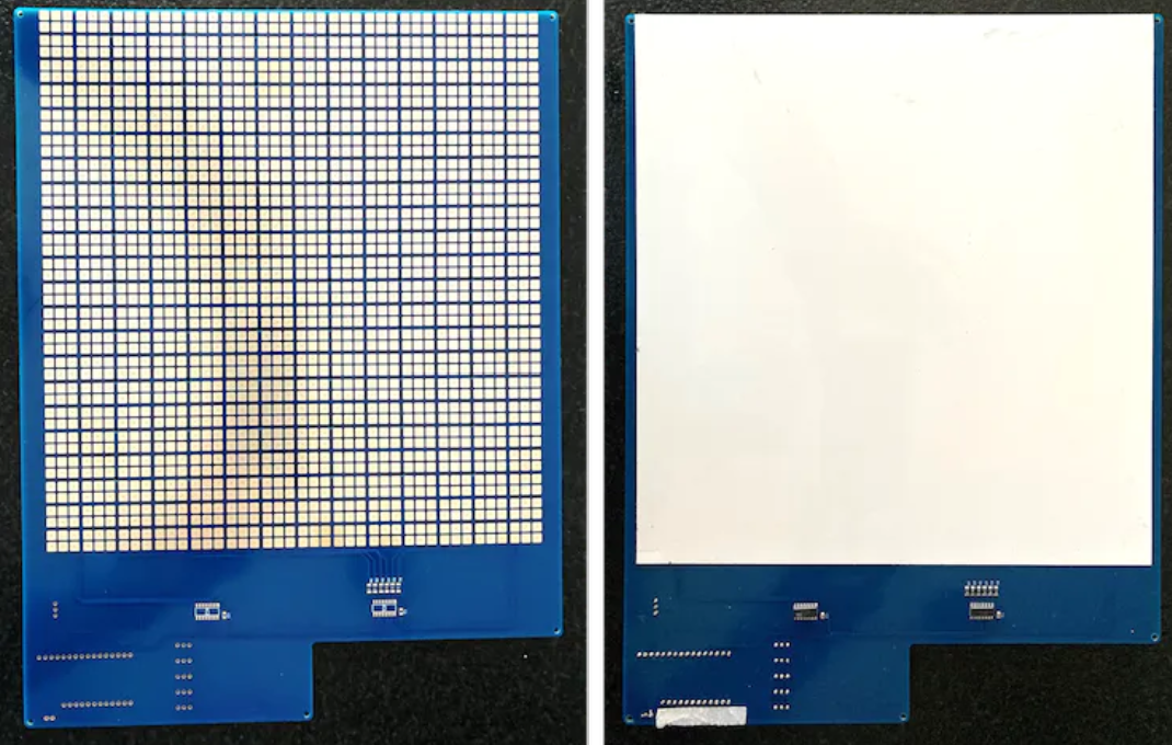
To cover the PCB copper pads (i.e., the "Touch Electrodes") and create the visual user interface, I tested various options and settled on Post-it Dry Erase Whiteboard Film Surface, which allows to draw different keyboard layouts in the letterboard, and being Post-It, can be safely removed in case something comes up. See below the bare PCB with exposed copper pads and covered with Post-It Whiteboard.
![]()
-
3Software Considerations
Software
I started this project using Visual Studio Code for editing and the Arduino IDE 1.8 for compilation & upload (by declaring "Outside Editor" in the Arduino IDE's preferences). Now the Arduino IDE 2 makes this unnecessary (and it does have many useful features).
MPR121
Having gone through Adafruit’s learning guide (a good starting point) for their Capacitive Sensor Breakout Boards, I reached the limit of what can be done with the Set Thresholds public method of the MPR121 library.
I created a program for calibration of individual electrode sensitivity using baseline filtering, touch filtering & debounce, and the MPR121's autoconfigure feature, all during program execution, thus avoiding the need to recompile & reload with each scenario being tested.
Its objective is finding the optimal calibration parameters to be later implemented in the appropriate production program. I posted the summary of the MPR121 capabilities, the NXP application notes, the changes made to the MPR121 library in a tutorial on the Arduino Forum. The code is on Github.
Interrupts
Reading the SPDT switches could be done in the main loop(), but I wanted to use Interrupts (to learn about them and to avoid using loop() cpu time, although now I see it is overkill, but that's what makes it fun!).
I went through Function Pointers in Gammon's Forum, but my comprehension ability hit a wall. Passing arguments to Interrupt Routines was the solution (the forum discussion includes advanced topics like compile-time recursion and lambda functions both of which I did not use). Also, useful to consider as consultation material, the Espressif Docs on GPIO: Interrupts.
BLE Keyboard
The only ESP32-BLE Keyboard library I've found is T-vK's. To minimize memory usage, it can use NimBLE-Mode albeit with some mods to compile in Arduino. Some tinkering is necessary to compensate the speed at which iOS can receive and Text-To-Speech characters and words.
Also, the library handles only standard US keyboard, to special characters (like "ñ") have to be sent using the equivalent keyboard character (like ";"),
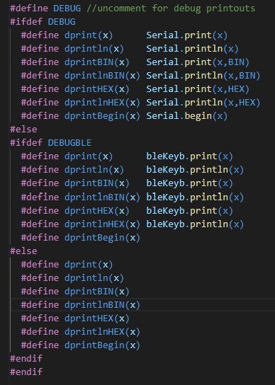
Debug Output
A nifty method I found for managing debug output is creating a DEBUG variable and redirecting the Serial.print() commands to the bleKeyboard (for wireless serial outout), to themselves (for standard serial monitor) or to null (for production versions).
![]()
Permanent Data Storage
To store the selected configuration parameters, I use Espressif's Preferences library (unique to arduino-esp32, the replacement for the Arduino EEPROM library). Works best for storing many small values, rather than a few large values (in that case, better to use LittleFS as file system library instead). Don't miss Random Nerd Tutorials' take on the subject.
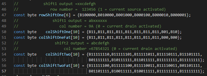
LED Matrix
This being a 10x6 matrix (columns 1 thru 10, rows 1 thru 6) managed by two 74HC595 shift registers (see schematic), specific data bytes had to be assembled for the different letterboard configurations (small ABC, large ABC and QWERTY) using one or two LEDs per letter for the shift out operations.
These two guides helped in understanding Serial to Parallel Shifting-Out with a 74HC595 and the advanced IO function shiftOut().
The data bytes are assembled in Declarations.h as seen here:
![]()
Letterboard Configuration Mode
When the user sets all of the SPDT 5 switches to OFF (i.e., no letter, no word, no phrase output and no LED nor Buzzer feedback), the system enters config mode.
At this point, all touch detection and management routines are focused on the three possible letterboard configurations: touching anything on the rightmost third of the board (column > 14), sets layout #3, touching anything on the middle of the board (columns > 7), sets layout #2 and touching anything on the first third of the board sets layout #1, saving these changes in permanent memory via Preferences.
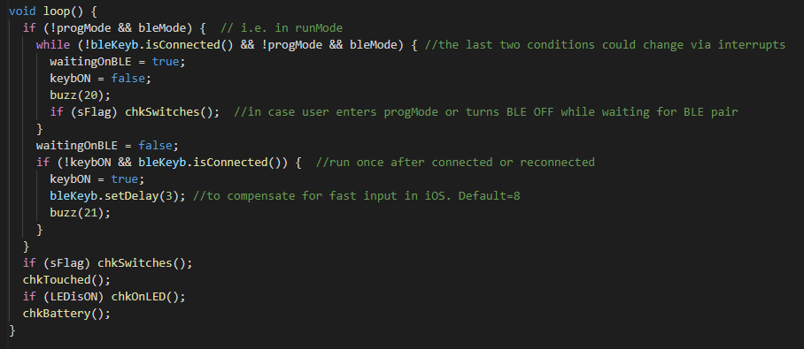
Program Structure
All code is developed using functions (subroutines) with descriptive names and thoroughly commented to assist in understanding the code. This allows for a short and simple main loop():
![]()
There are 5 files (I name them .h to bypass the alphabetical order assigned by the Arduino IDE if they were all named .ino):
- RC3.ino (i.e. Release Candidate 3) is the main program and contains the setup() and loop() functions.
- Declarations.h has the variables, constants & #includes, all grouped by function.
- MPR121.h is the modified & simplified version of the standard MPR121 library contained now in a single file (i.e., no.cpp file)
- fCore.h contains the core functionality routines (programming mode, read & output touched data, manage config switches & interrupts)
- fSupport.h contains the supporting functionality routines (buzz, LEDs, symbol tables, battery).
- tunes.h contains the melodies and routines used in the config mode and at system startup to identify which mode is selected. The tunes functions were created by Robson Couto
-
4Using the Letterboard
There are three letterboard formats: Large ABC, Small ABC and QWERTY.
Each can be selected by entering Config Mode (putting all Functional Switches to OFF) and touching the first, middle or last third of the board, respectively. To assist in identifying the selected format, that third of the LED Matrix is flashed and a distinct tune is played for each.
The selected format is then drawn using standard whiteboard markers as seen here for the Large ABC format:
The voice can be selected from the iOS device's Accessibility configuration. Using the Functional Switches, the user can choose to send letters, and/or words and/or sentences to be read out loud:
Erasing and drawing a different format is just as easy:
Bluetooth RPM Letterboard
Capacitive touch, field programable whiteboard giving distinct multi-sensory fingerprints to letters in RPM therapy for non-verbal autistics


Discussions
Become a Hackaday.io Member
Create an account to leave a comment. Already have an account? Log In.