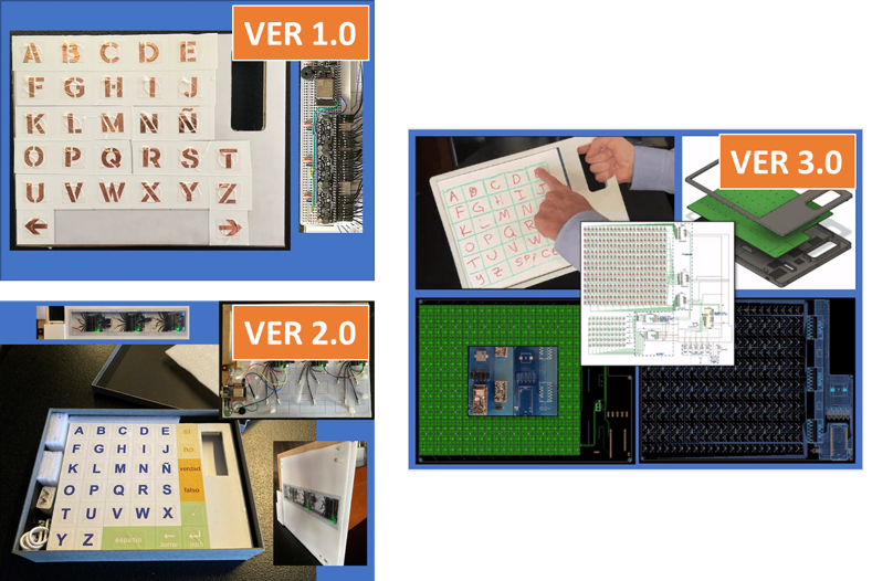
This is the third iteration at building a usable tool for RPM communication. They have evolved in functionality and complexity:
And as in every version, there have been lessons to be learned:
- The SPDT switches are affected by ground bounce. When using interrupts, the Interrupt Service Routine (ISR) is triggered continuously when more than 2 pins are LOW. The issue is currently managed in code and could be further mitigated (albeit not eliminated) by not using interrupts. Must read more on decoupling and possibly test using Wokwi.
- The PCB can benefit from using 3 distinct types of ground (for analog, digital, and power circuits) with their respective cap separators.
- The MCU's antenna is placed over the ground plane which can badly detune the antenna and impair the WiFi / Bluetooth performance. Beginner's luck: I placed the MCU over headers, creating a 2mm air gap that mitigated (but not eliminated) the issue.
- Increase Copper Weight of Outer Layers to possibly increase capacitance of the touch pads (albeit nearly double the cost if 2oz copper weight), Look at Trace Resistance Calculator from AllAboutCircuits,
- Use a connector instead of soldering the battery cables directly to holes in the PCB: with a little manipulation, it breaks off.
- The smallest SMT were the caps @ 0805. Consider using bigger components since we don't really have am issue with available real-estate on the PCB.
- ESP32 Usable Flash Memory: the ESP32 development boards from non-Espressif manufacturers usually can't use the full on-board memory because their partition schemes on Espressif's Arduino ESP32 core are limited. A quick (manual) fix is to put a partition.cvs in the sketch: it will be picked up instead of the one in the menu. Adafruit has "...a PR to Espressif to fix the partition scheme for 8MB. It may take a while for them to review and merge...".
Discussions
Become a Hackaday.io Member
Create an account to leave a comment. Already have an account? Log In.