 Stephane
-
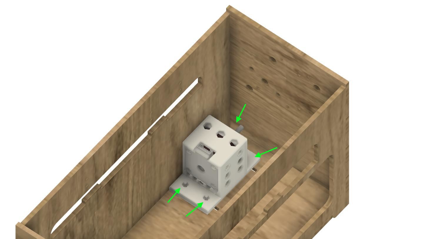
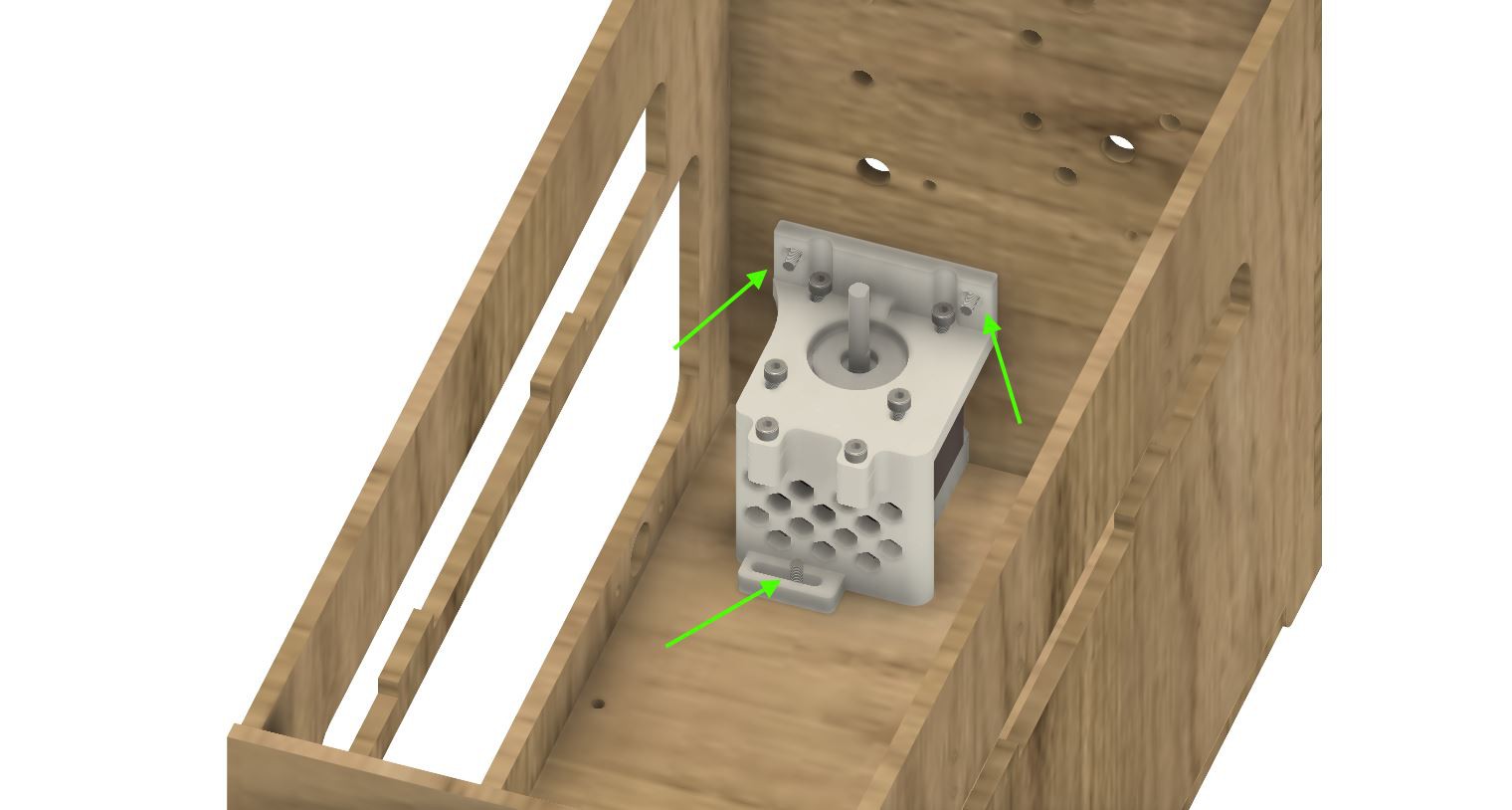
11Fix X and Y Motors
Fix the X Motors with 4 M3-14 screw, waschers and M3-NYL nuts
![]()
Fix the Y Motor 3 M3-14 screw, waschers and M3-NYL nuts
![]()
-
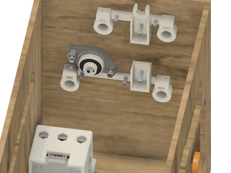
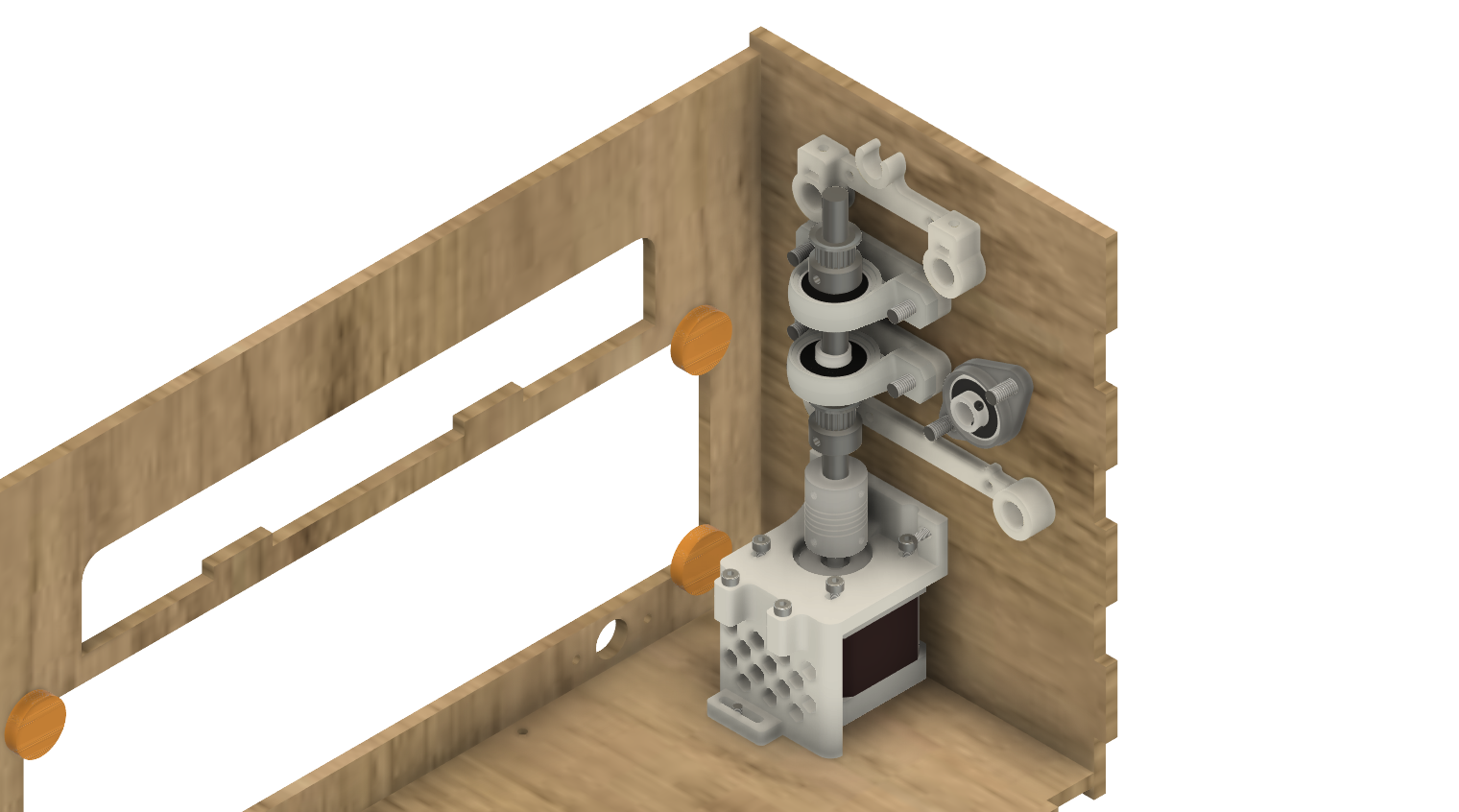
12Assembling left side
Fix 3d printed parts BOTTOM_AXIS_left and TOP_AXIS_left on the frame with M3 washers M3 Nyl nuts and M3-14
Add Belt tensionners DRIVEN_PULLEY_housing with 2 M3-20, M3 washers and M3-NYL
Add KFL-08 with M5-18, M5 wascher and M5-NYL
Fix the 20T bore 3mm pulley with M3-25 and M3 nyl
![]()
-
13Assembling right side
Fix 3d printed parts BOTTOM_AXIS_right and TOP_AXIS_right on the frame with M3 washers M3 Nyl nuts and M3-14
Fix 3D printed parts KP08_support and KP08 on the frame with M5 washers M5 Nyl nuts and M5-25 screw
Fix a KFL08 with M5 washers M5 Nyl nuts and M5-25 screw
build the axis with 110mm rod 2 GT2 20 teeth pulley and 8mm-5mm coupler
![]()
-
14Build bottom carriage
insert 2 330mm/8mm rod in the support, with the bottom carriage and the endstop support.
![]()
fix ~600 mm GT2 belt on the carriage, passing by the 2 pulleys on right and left.
-
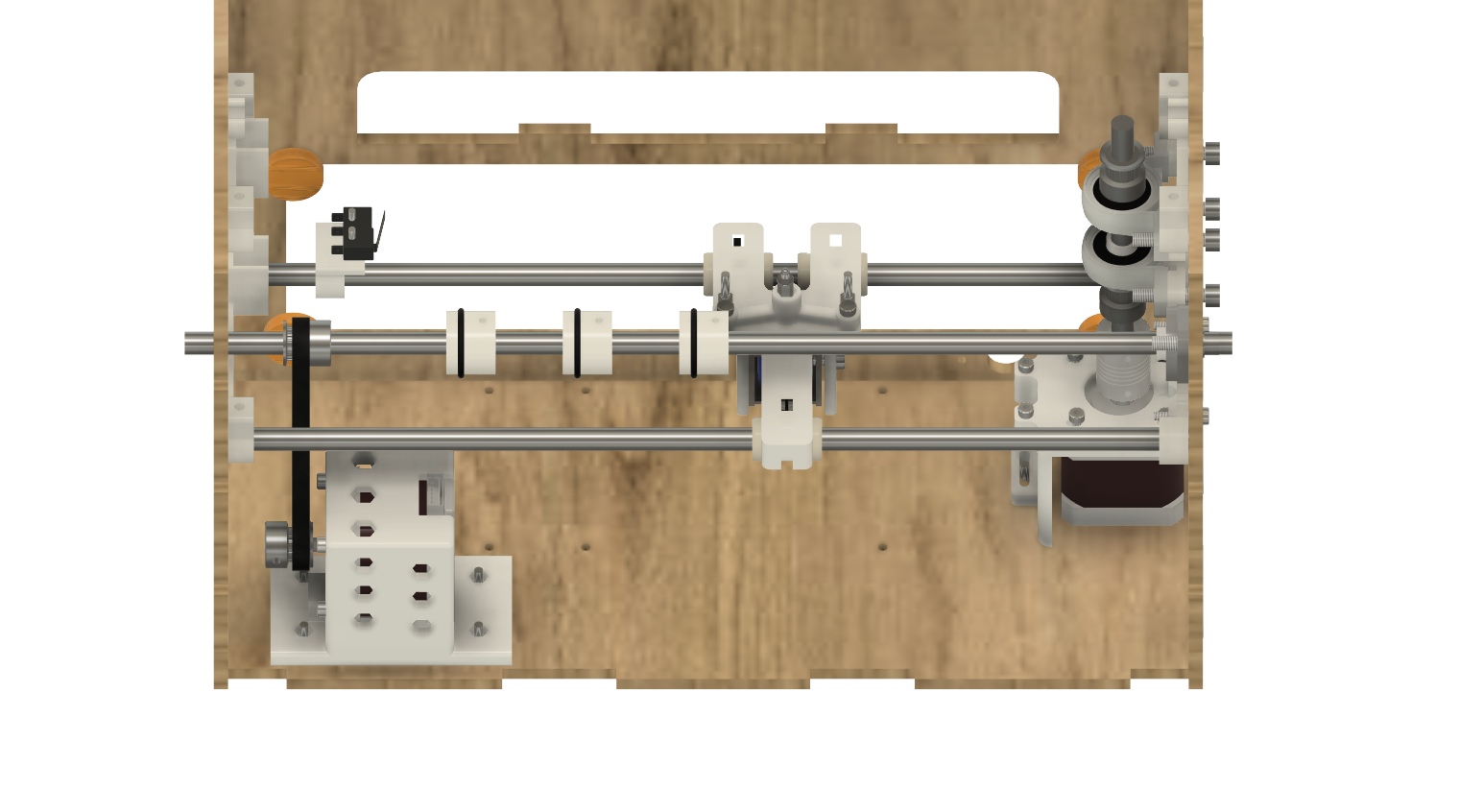
15Build paper advance
insert the 360mm/8mm rod with a GT2 pulley 20 teeth, 3 paper roll with o-ring, and 200mm GT2 belt
![]()
-
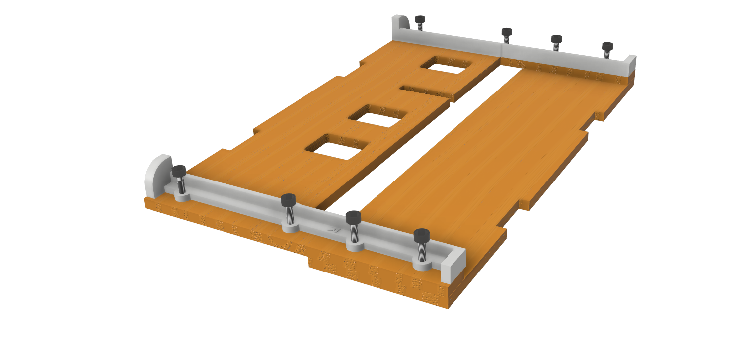
16Paper support
fix PAPER_GUIDE_left and PAPER_GUIDE_right printed parts with M3-14 and M3-16 screws, M3 waschers and M3 Nylstop nuts
![]()
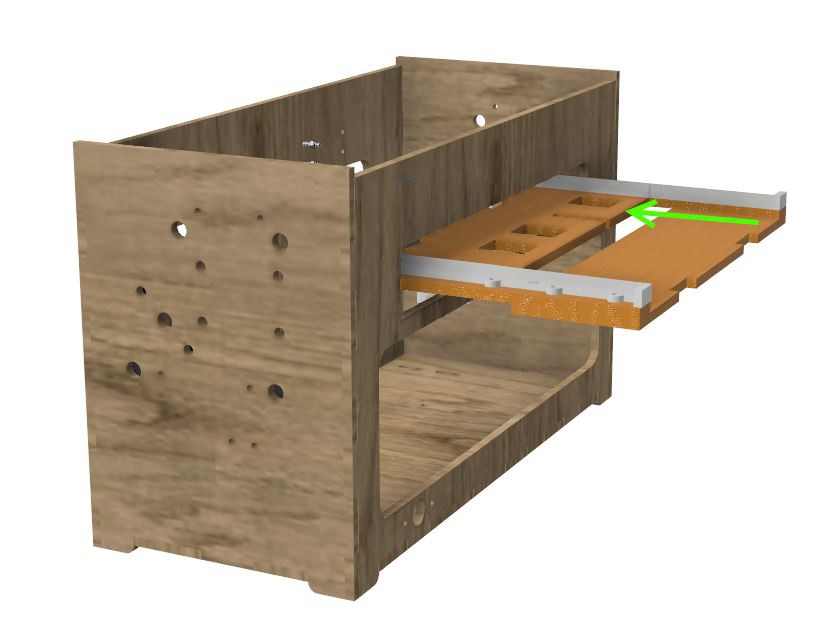
fix the paper support in the frame
![]()
you will need to adjust the paper roll for the paper support to take in place.
-
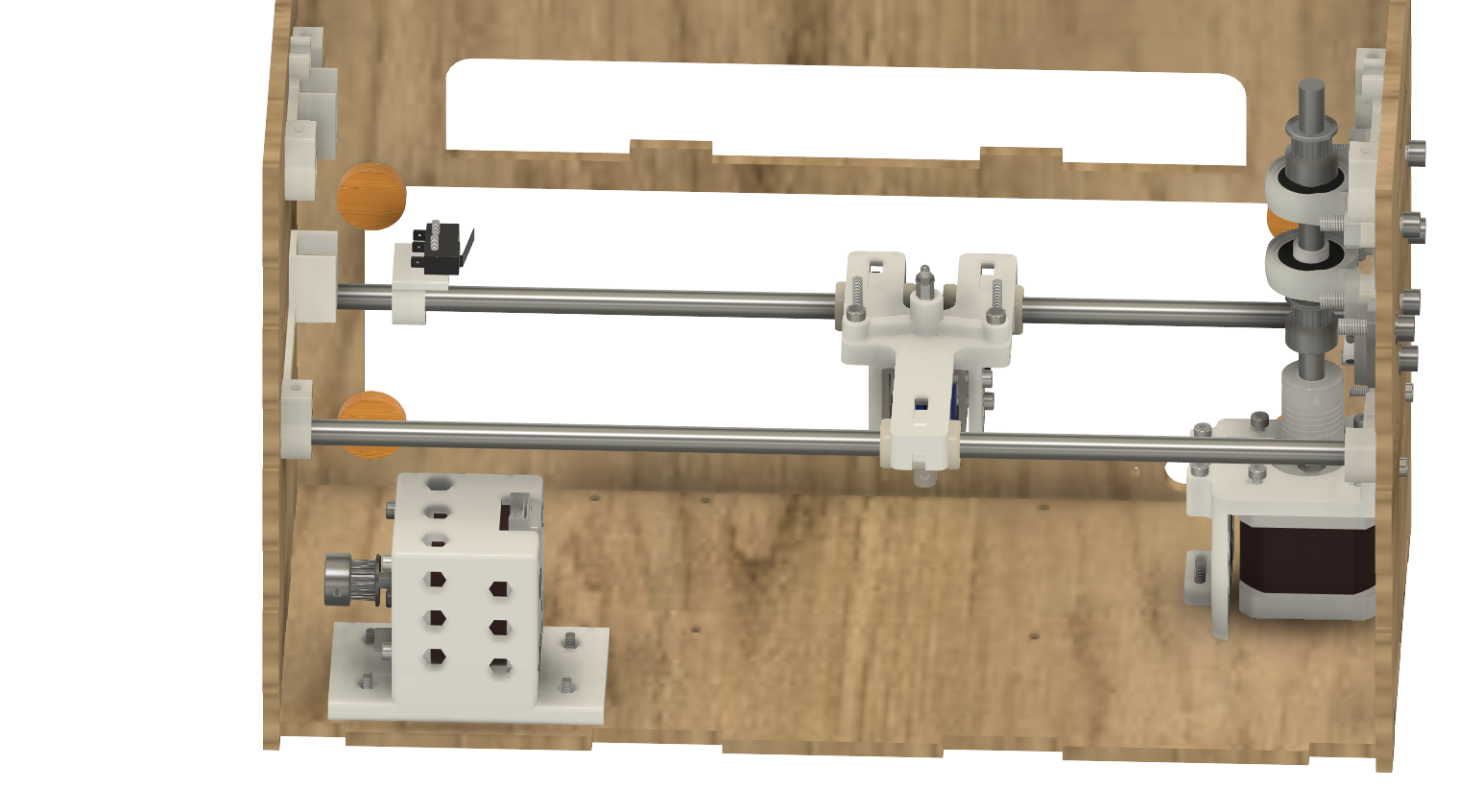
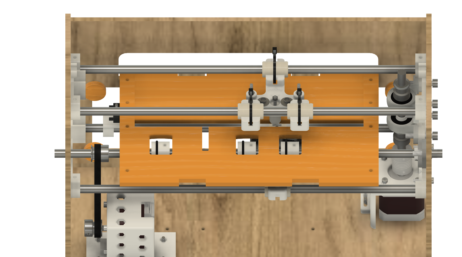
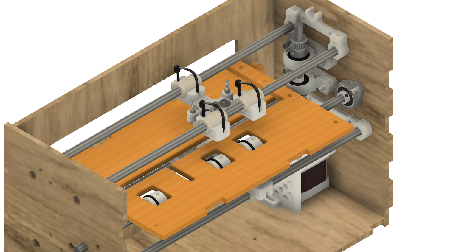
17Build top carriage
Insert two 330mm/833 rods in the frame with the top carriage
![]()
![]()
add ~600 mm of GT2 belt on the top carriage, passing by the 2 GT2 pulleys on the left and right.
-
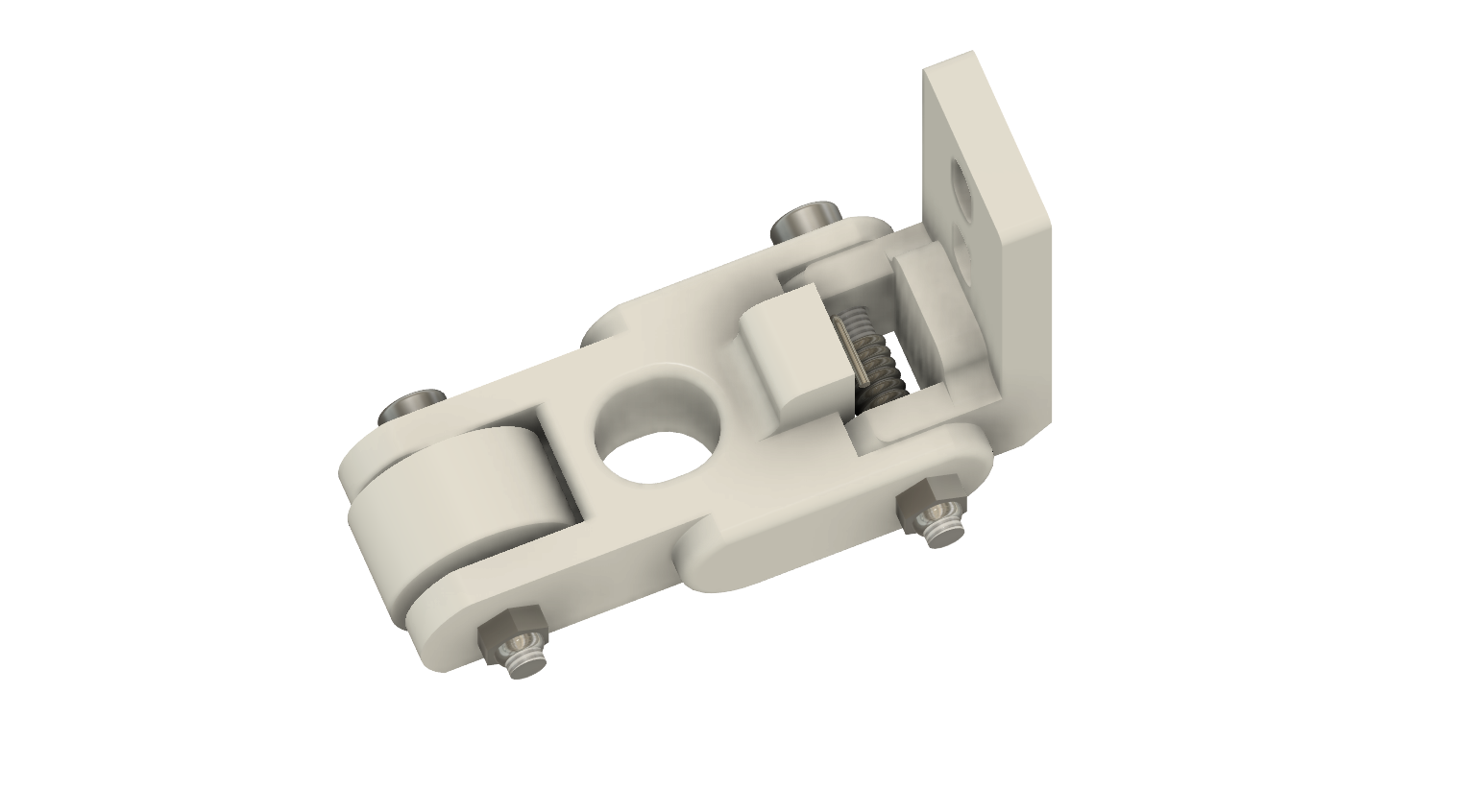
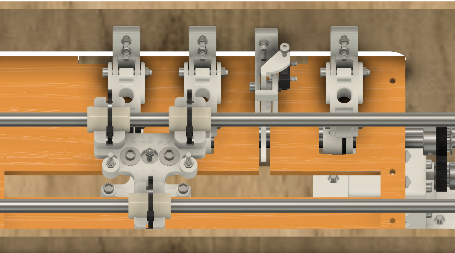
18Paper clibpoard and limit switch
Assemble 3 paper clipboards with 3d printed parts clipboard2_support, clipboard2, CLIPBOARD2_WHEEL using M3-25 and M3-20 screws, M3 nyl nuts and GT2 tensionner spring
![]()
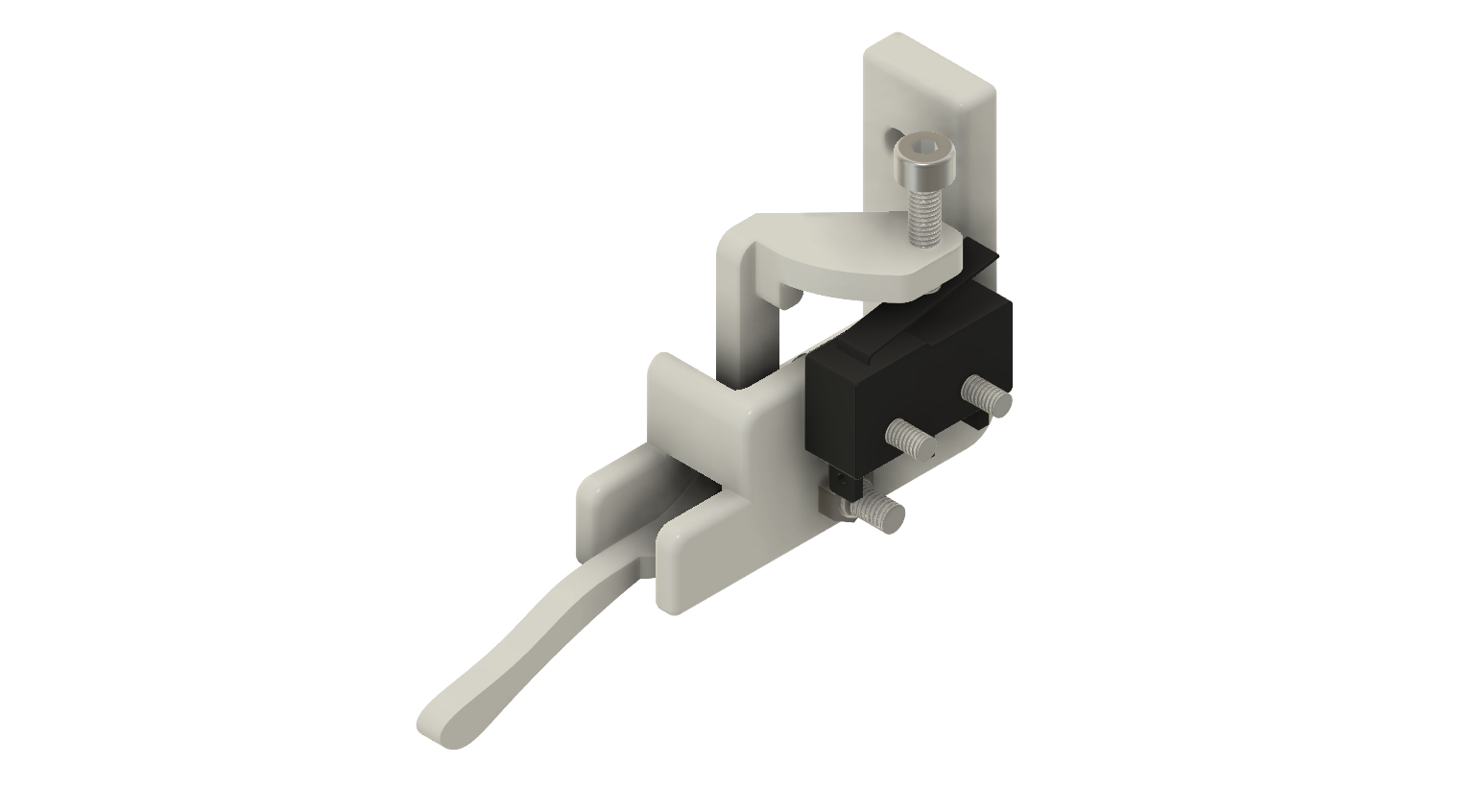
Assemble paper (Y axis) limit switch with 3d printed parts ENDSTOP_Y_support, ENDSTOP_Y_lever with M3-20 screw and M3 nylstop. Fix the limit switch with two M2.5-14 screw and M2.5 nylstop nuts. Put an M3-12 screw on the lever.
![]()
Mount the 3 clipboards and the limit switch on the frame with M3-13 screw, M3 washers and M3 Nylstop nuts
![]()
-
19The final
- Adjust everything, tight the needed screws and belts
- Adjust the top and bottom carriage, the Braille stylus of the bottom carriageneed to slighty enter in the anvil of the top carriage.
- Mount the electronic board with drivers
- Wire the 12V alimentation
- Adjust the motor drivers if needed
- Wire the 2 limit switches on the board
- Connect the board to a PC with a USB cable
- Launch the arduino IDE, set it to MEGA2560 as CPU, and set the COM port of the board
- Open the sketch marlin.ino and upload it to the board
Close Arduino Ide and launch Pronterface to check everything
- Check the limit switches
- Check the Electromagnet with M3 S1 GCODE command
- Check X Homing
- Check Y Homing with a sheet of paper
if anything go wrong, address the issue and restart the tests
-
20Use
Install the latest version of AccessBrailleRAP (https://github.com/braillerap/AccessBrailleRAP/releases)
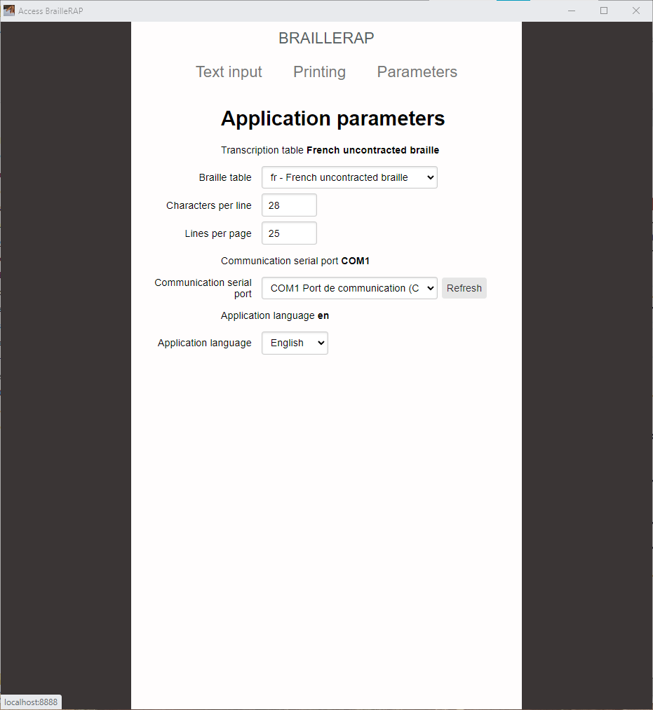
set the parameters :
- Braille Standard (you have the choice between 200 combinations of Braille Standard and language)
- Communication port
![]()
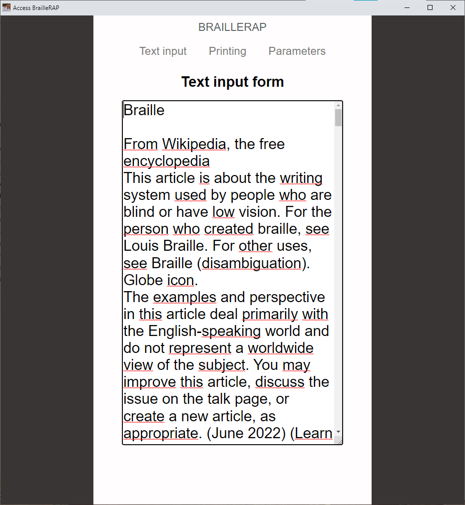
Enter some line of text, or copy paste something
![]()
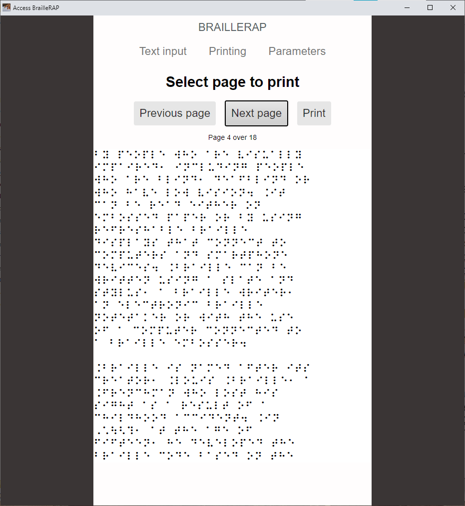
Translate in Braille, select the page of your choice
![]()
Use the print button
BrailleRAP DIY Braille embosser
An Open source Braille embosser in the spirit of RepRap
Discussions
Become a Hackaday.io Member
Create an account to leave a comment. Already have an account? Log In.