 Stephane
-
1Prepare material
Put your hand on all the needed stuff and gear.
The frame parts:
Usually, we use 5mm plywood. But you can use any 5mm thick material that you can cut in a laser cutter, as acrylic PMMA for example.
3d printed parts :
Print all 3d parts, it take some times, more than 20 hours depending on your 3d printer. Usually, we use ABS, but PLA is an alternative, you can test PETG. As there is 40 parts to print, you will find a detail listing in printed_part directory.
-
2Bonding the frame
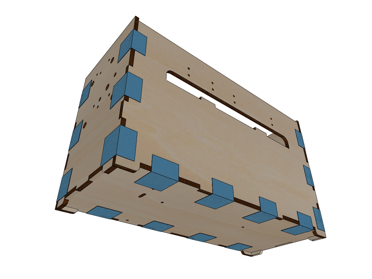
Put all the laser cut parts as bellow on a table . Pay attention to clearly identify each part orientation (use holes in the parts to find the correct orientation)
![]()
Glue all the notches and build the chassis, secure your build with some tape (blue tape for example)
![]()
-
3Bonding paper support
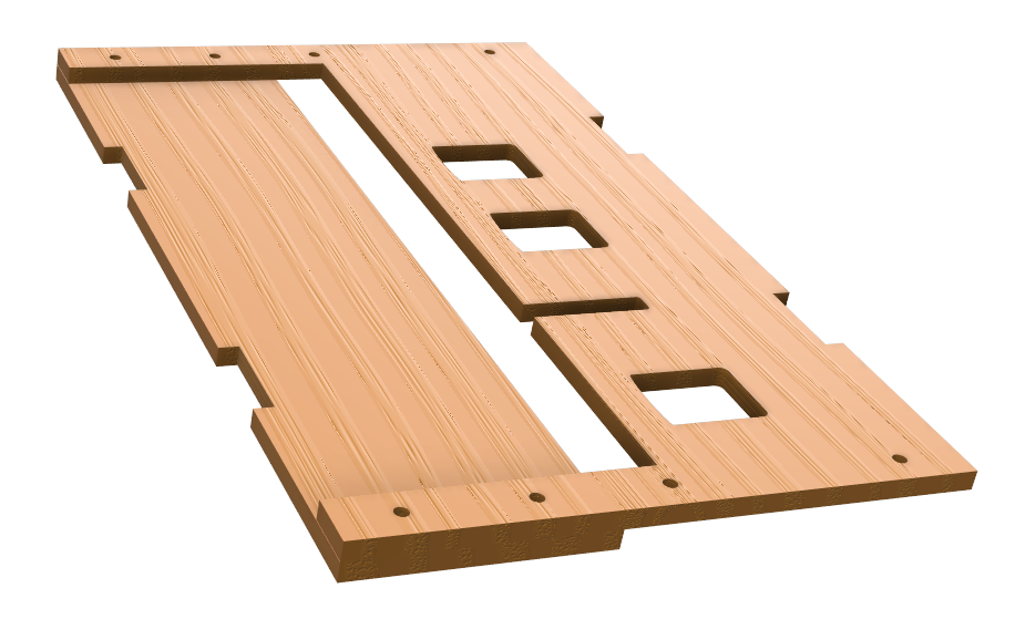
Glue the lower support under the upper support. Place screws in drillings to properly align the parts. Use clamps to maintain the two parts together
![]()
-
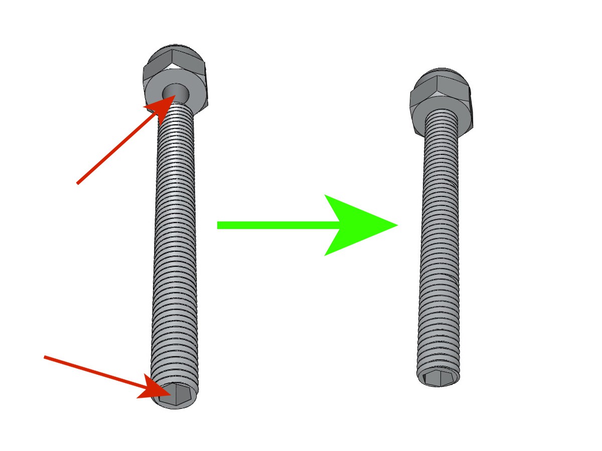
4Prepare the Braille Stylus
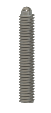
Take an M3-16 grub screw with but end. file patiently the but end to obtain a smooth end like this
![]()
-
5Prepare X and Y motor supports
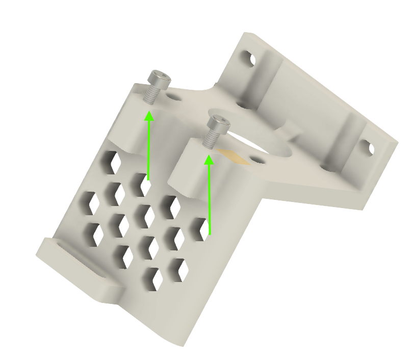
Screw together the parts XMOTOR_support2 and XMOTOR_support2_1
![]()
Fix a NEMA17 Motor in the X support with M3-8 screw
![]()
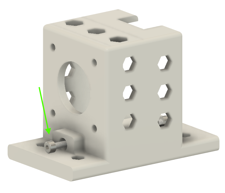
Screw together the parts YMOTOR_support2_200_1, YMOTOR_support2_200_2, YMOTOR_support2_200
![]()
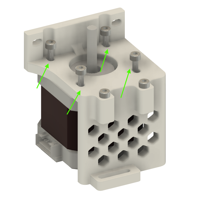
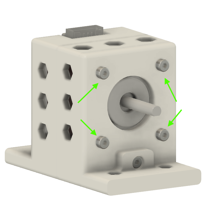
Fix the second NEMA 17 motor in the Y support with 4 M3-8 screws
![]()
fix GT2 20 teeth 5mm bore pulley on the motor axis
-
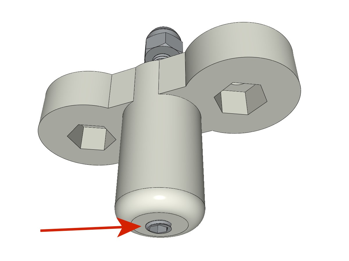
6Prepare Axis parts
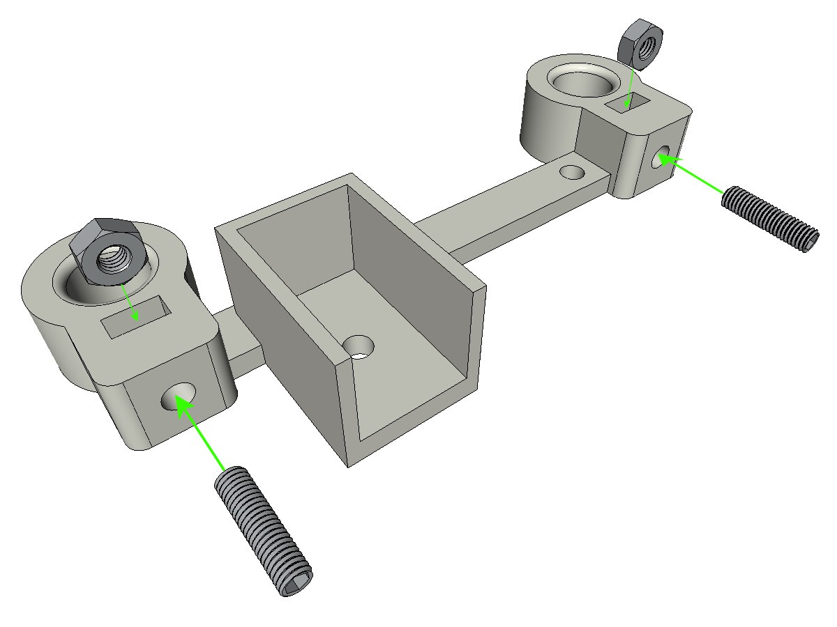
The 3 parts to be assembled are BOTTOM_AXIS_left, TOP_AXIS_left, TOP_AXIS_right.
put 2 M3 nuts and M3-12 screw in each parts. You can use grub screws or standards one
![]()
-
7Prepare the X and Y Limit switch
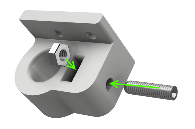
put 2 M3 nuts and M3-12 screw in SWITCH_X_support. You can use grub screws or standards one
![]()
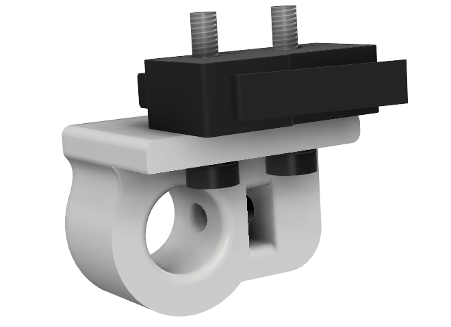
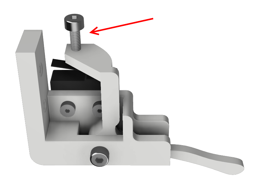
screw a wired limit switch on the SWITCH_X_support, pay attention to the screw orientation
![]()
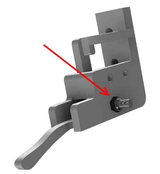
Fix the lever ENDSTOP_Y_LEVER to the support ENDSTOP_Y_support with an M3-20 screw and an M3-NYL nut. Make sure that the lever can move freely.
![]()
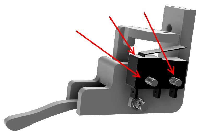
Fix a wired limit switch on the support
![]()
Put on M3-12 screw on the lever
![]()
-
8Prepare the Anvil
Glue with cianoacrylate the thread of the cap nut and the M3-30 screw at the end side
![]()
Tap the printed part FEMALE_shape and screw the anvil
![]()
-
9Prepare bottom carriage
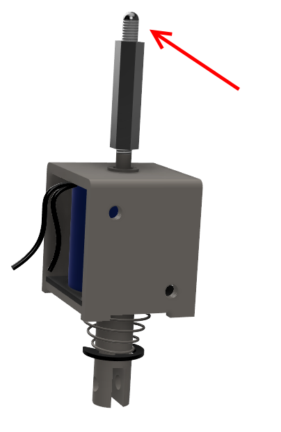
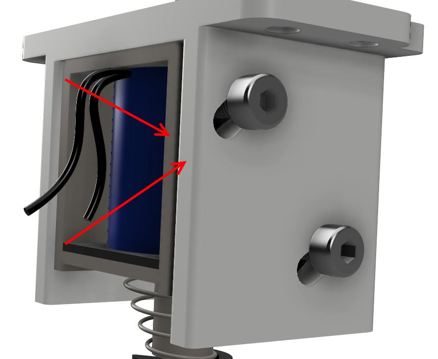
Remove the nuts of the electromagnet and replace it with an M3 18mm hex spacer
Screw the stylus at the end of the spacer, let the stylus to extend 6mm above the spacer
![]()
Fix the electormagnet in the ELECTRO_MAGNET_housing printed part with 2 M3-8 screws and M3 waschers. Take attention on adjusting the edge of the electromagnet with the edge of the printed part
![]()
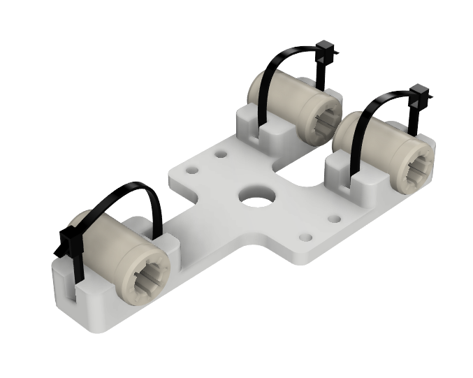
Fix 3 RJ4JP-01-08 on the 3d printed part BOTTOM_trolley
![]()
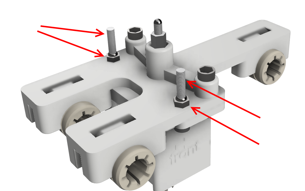
Fix together the botom carriage the elctromagnet housing and ELECTRO_MAGNET_guide with M3-18 screw and 2 M3-NYL nuts. Use 2 M3-20 screw and M3-NYL nuts to build the belt attachment.
![]()
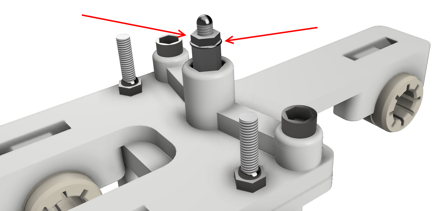
Use a standard M3 nuts and a washer to secure the stylus
![]()
-
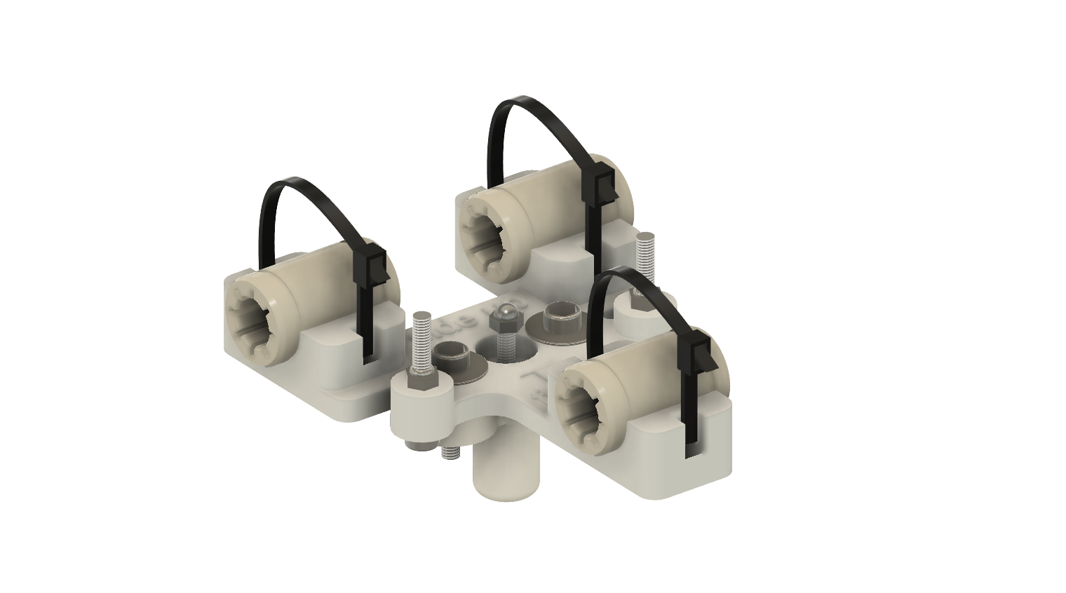
10Prepare top carriage
Assemble the FEMALE_shape on the TOP_trolley with 2 M3-12 screws, M3 washers and NYL M3 nuts. Build the belt attachment with 2 M3-20 screws and 2 M3 Nyl nuts. Fix 3 RJ4JP-01-08 with collets.
![]()
BrailleRAP DIY Braille embosser
An Open source Braille embosser in the spirit of RepRap

Discussions
Become a Hackaday.io Member
Create an account to leave a comment. Already have an account? Log In.